Weeks commencing 7, 14 and 21 June 2021
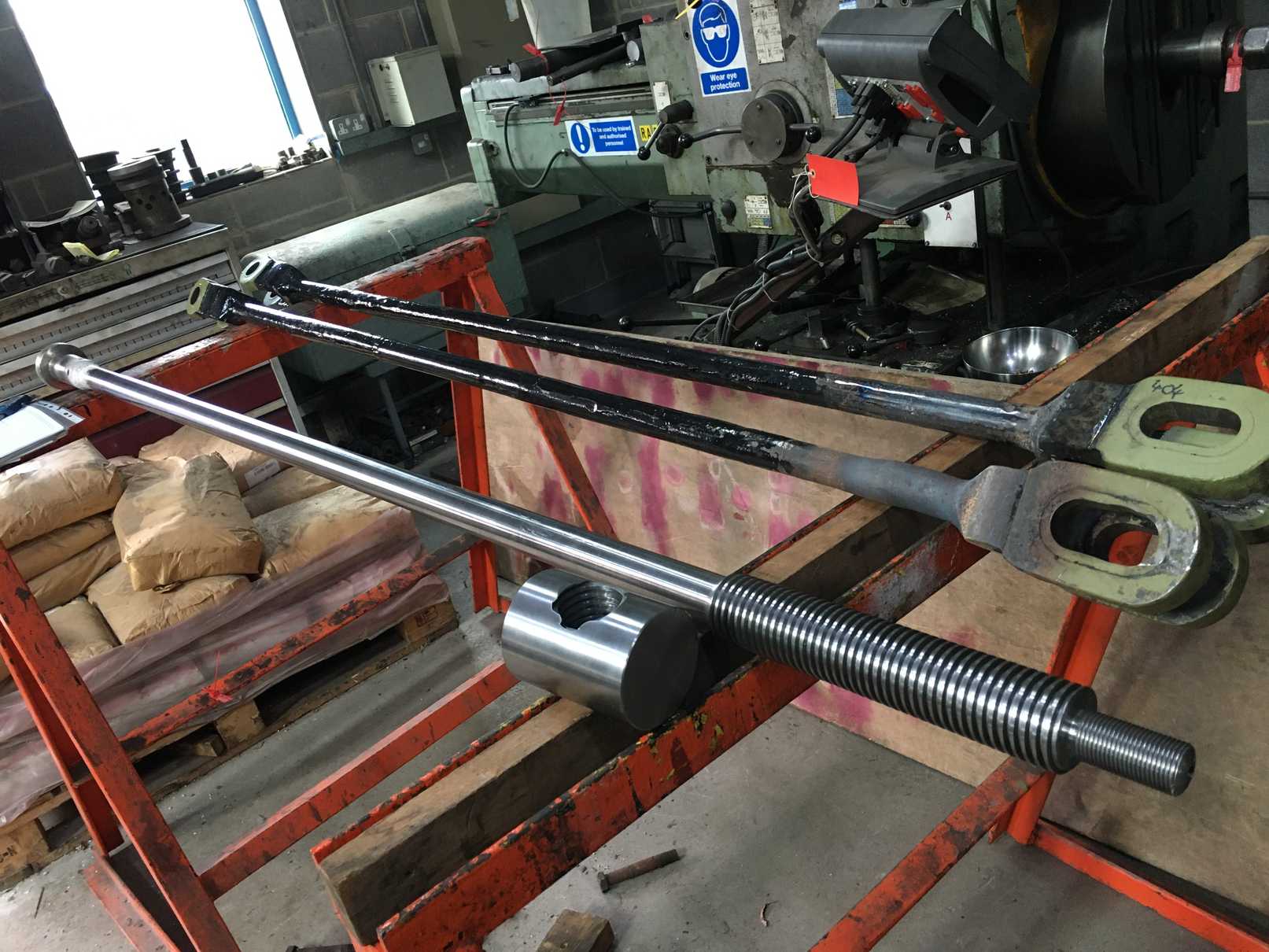
The new handbrake screw has now been collected from contractors. It has a new shaft and screw and is welded to the old top section where the handle is fitted. It has been welded and examined by an independent third party. A new nut has also been made. The nut has now been drilled and tapped and fitted with a grease nipple. The assembly is now being painted before fitting.
Work on the Cartazzi trailing horns continues with the left side progressing. Work on the right side has started.
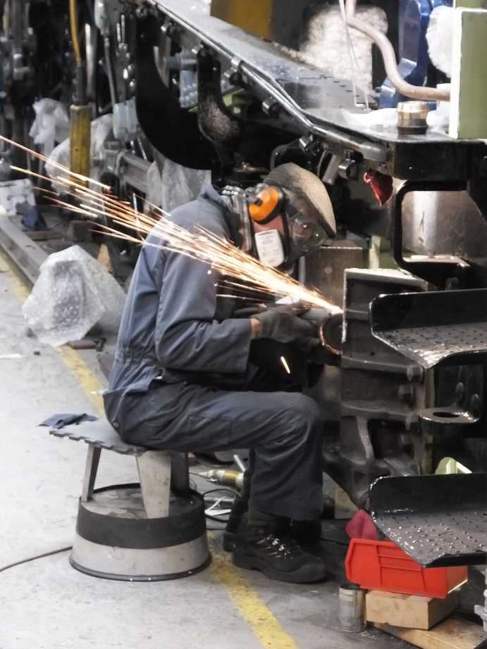
The left Cartazzi bearing has seen some further scraping in.
The left cladding panels approach completion with the left throatplate panel now being painted inside before final fitting. Since the last report the left and right panels to the rear of the steam dome, the last over the boiler barrel, were fitted. The left required a new bottom roll and a piece inserted to correct the geometry so the streamlining ran on to the next panel correctly.
The left throatplate panel has a lower section made from thicker material as it is pressed in to a more complex shape than the other panels and is obviously very old. The upper part is in the same thickness as the other panel material. The 2 sections meet about half way up and look to have been originally welded where the lower panel was thinned. At some time the panel had been cut through and pop-riveted and screwed to a joining strip. The strip has now been removed and the sheets re-welded along a new strip. The bottom roll was very corroded and had a number of overlays only fully apparent after a lot of filler was removed. So it was decided to replace the bottom rolled section. This had to be done in 4 pieces to match the shape of the old panel.
While the paint on the inside of left throatplate panel dries the last panel in front of the cab is being trial fitted and the insulation on the boiler trimmed back around the boiler doors. This panel is the simplest on the loco being just a flat sheet wrapped on to the crinoline with just 2 securing screws on the spine.
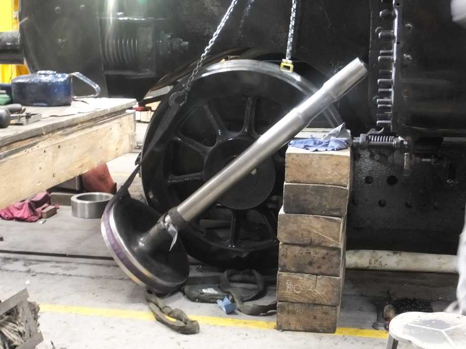
The outside connecting rods are complete and ready for fitting. The last operation was putting the right little end up on the Bridgeport to skim the little end bearing.
The coupling rod knuckle pin nuts were finally tightened and the cotters fitted.
All the piston valves complete with rings are now fitted. The middle valve having the head positions set and a new ground shim fitted.
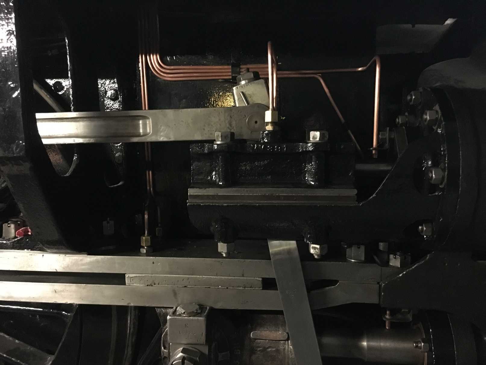
Fitting all 3 piston valves has allowed the 2:1 conjugated gear lever to be finally fitted in place.
All the valve covers and guides have been painted with the outside ones now fitted. New shims for the guides have been fitted and the clearances checked. A bit of scraping and tweaking was required to ensure the correct clearances.
The outside valve gland assemblies have also been fitted and the Piping Team have begun final fitting of the lubrication pipes. Some smart new lubrication pipe brackets that direct the oil flow to the valve spindles have been made.
The outside pistons are now both fitted with the heads and rods cleaned while the cylinder sealing faces and covers are prepared. Annealed copper gaskets have been fitted.
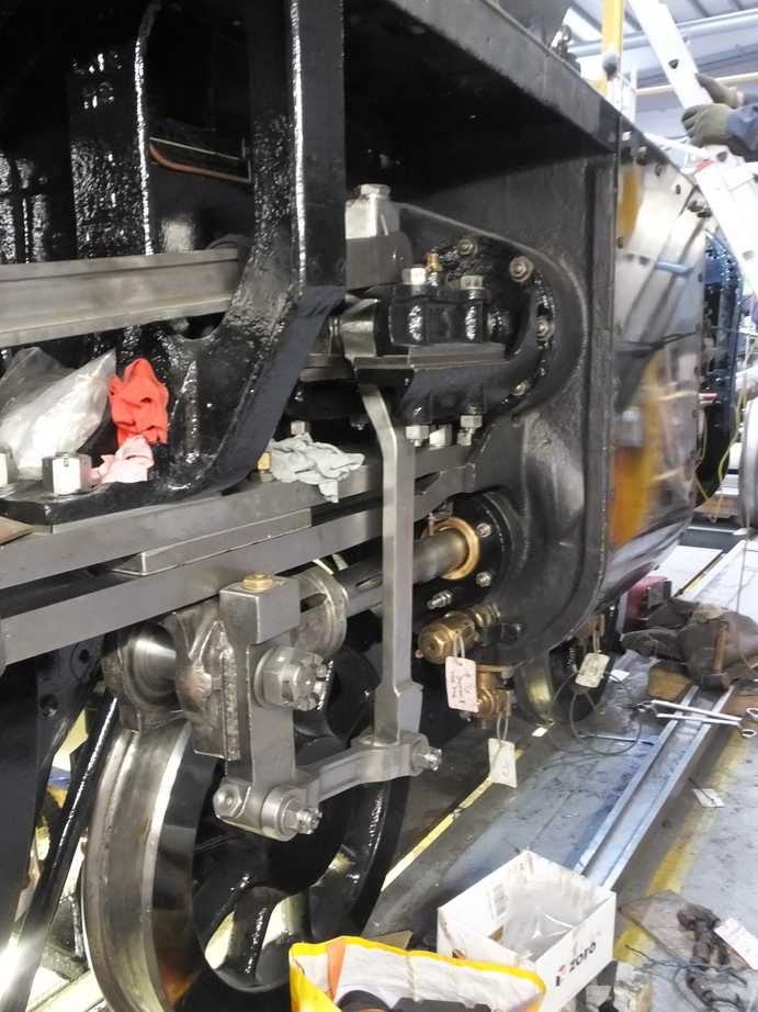
The outside piston rods have had their gland assemblies fitted with our CME inspecting and dressing the packings.
The outside pistons have been cottered to their crossheads.
Split cotter pins have been fitted to the valve guide bolts and gland studs, and to the last 2 left leading slidebar nuts.
The middle leading valve guides and valve cover are currently receiving final coats of gloss prior to fitting.
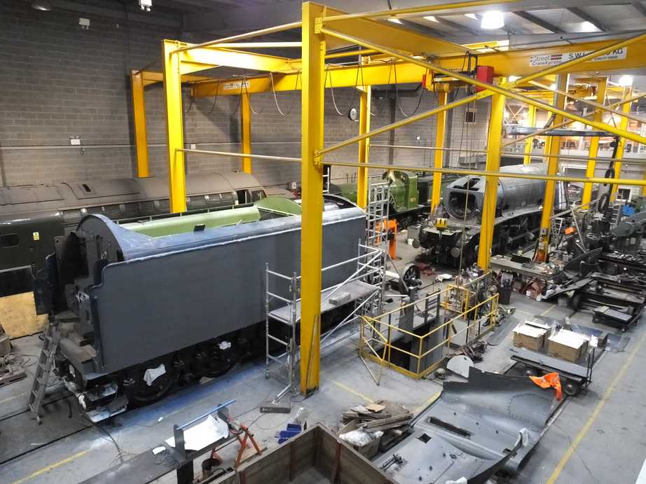
The tender has seen further filling and rubbing down on the left side streamlining above the beading, which is made up of a number of plates welded on over time. The plate edges have been filled which really takes away the obvious edges. A lot of work has been done along the tender side beading where corrosion repairs were made, and to remove evidence of service damage. The Painting Team have now given the sides and back of the tender a coat of undercoat.
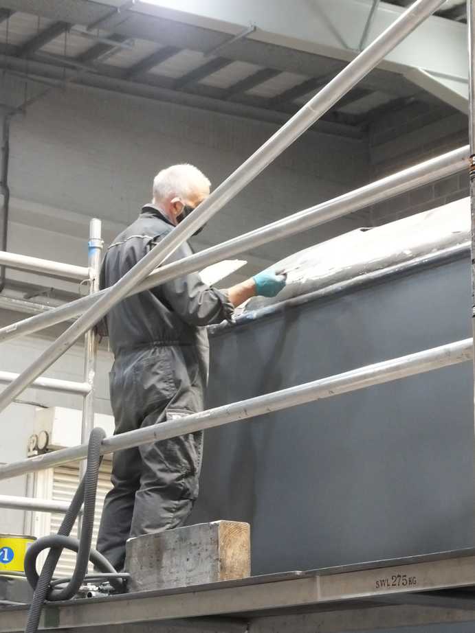
When the tender was modified with a higher front to match the A4 cab a butt strap was put on inside the tender platework. Since the replacement of the tender front plate at this overhaul it has no use but has now been refitted as an authentic part of the tender, complete with cosmetic rivet heads.
The tender sump and strainer have been refitted with the internal sieve box. The water feed to the injectors is taken from the sump. The 2 water valves and the connecting pipework have also been fitted. There’s still some bolting up to do but all the parts are in place.
A fabricated stand to support the check valve on the tender top air system has been fitted.
Inside the tender corridor the vestibule area and at the cab end the inside of the door has been needle gunned. In the corridor, loose paint and other rubbish accumulated during repairs has been removed in preparation for painting.
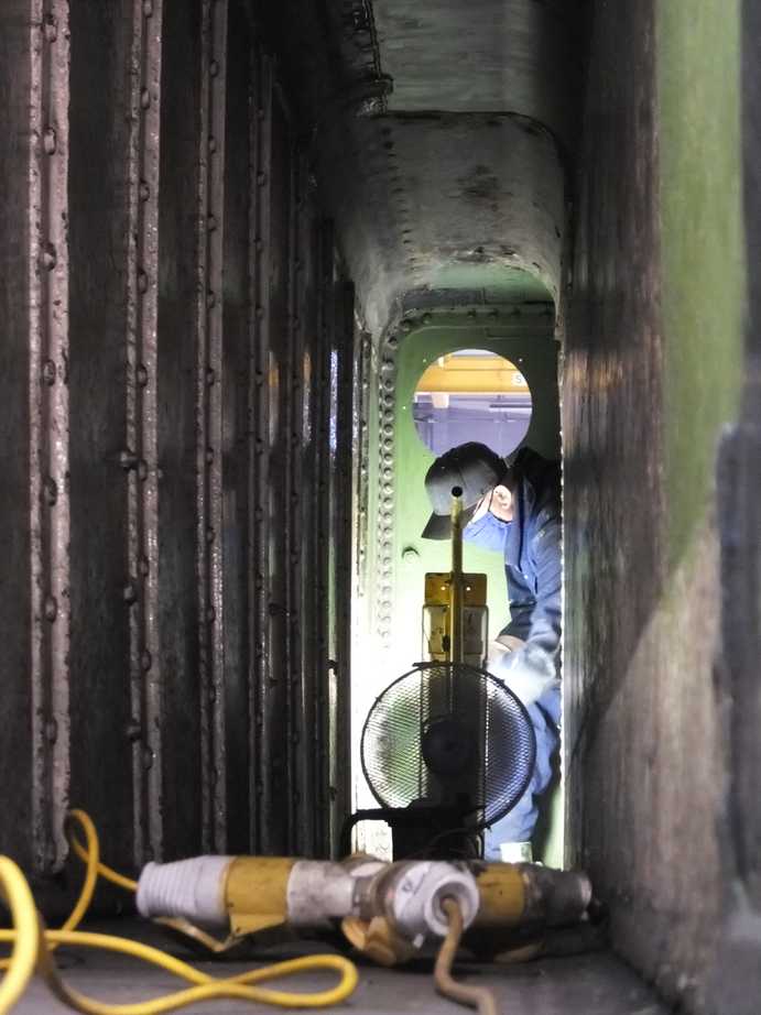
It was reported in the last update that we couldn’t get the cover to fit on the vestibule bellows spring as new bolting in the new plates fouled. The bolts have now been removed and the plates tapped out. New screws were fitted using Loctite to ensure retention, then the cover was fitted and the footplating next to it.
Inside the bellows vestibule the platework has been painted to gloss which has allowed the refitting of the GSMR rack. Work continues with fitting out the rack with the electronics unit, batteries and the rack enclosure cover plates.
The conduit from the front of the tender to the new battery box is being ran in.
The refurbished tender water level gauge has been refitted.
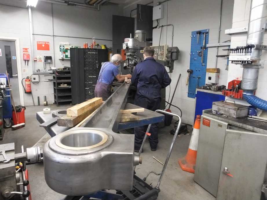
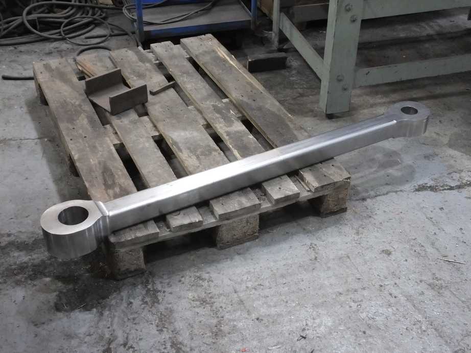
The main intermediate draw bar machining by contractor has now been completed and it has been delivered to York FOC for a tour of the loco.
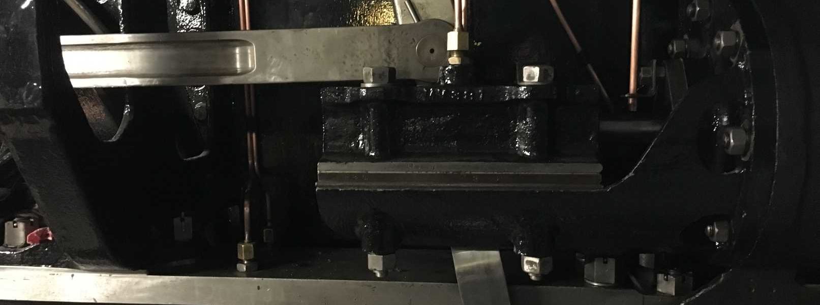
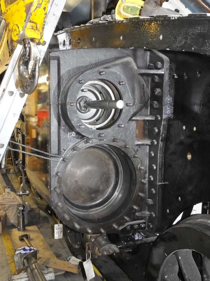
On the backhead a great job has been done of assembling the regulator cross shaft and stuffing box. A modification was made to the right support bracket that is fitted to the curved shoulder of the backplate. This is to ensure it stays in the correct location when tightened down to stop the end of the shaft binding. Inside of the stuffing box the cover and regulator reach rod clearances were also checked and some small adjustments made to ensure we have the correct clearances. Both regulator handles are now fitted and with the glands nipped the regulator operates smoothly. With our silky smooth reverser we will be spoiling the drivers.
On the backhead the Piping Team have ran in the steam heat pipe and the steam supply pipe to the air pump, from the manifold. The new air pump lubrication pipes are now ran to the backhead.
The AWS isolating valve has been stripped down and examined. It is no longer operative and is fitted as it is historically correct for our locomotive, but it is still connected to the vacuum system so has to maintain a seal.
The vacuum ejector was refitted, after the small ejector was refitted into the main body. Then the Piping Team trial fitted the vacuum brake pipe and reservoir pipes. A number of clashes were found so there is quite a bit of work to be done to get this assembly in. The ejector will have to be removed again when fitting the cab but hopefully most of the large diameter pipework can be left in place. The large pipes are joined with “air ministry” joints and a new cone has already been made to improve the pipe/flange/cone measurements. A lot more involved than a normal cone and nut arrangement.
The LNER blowdown valve has been refitted. The intermediate sealing cone was carefully dressed and it’s fit checked in the boiler and valve.
The boiler registration plate has been refitted after one of the 2 screws holding it on to the backplate was found to be corroded through.
At the back of the ashpan there are 2 cut outs to clear the frame pads the boiler sits on. To ensure the ashpan didn’t foul when fitting the boiler these cut outs are filled after fitting. New steel has now been welded in. It is important that it is not possible for hot ash to fall from the loco when in traffic.
The trailing grate support has been built up by and inch or so, this is to level this section of the grate as when tried in it was found that the grate sloped back, whereas it should be level. Lifting the back of the grate also gives us an extra inch of head room for routing the new ashpan sprinkler pipework. New material was added to the existing grate support.
The new ashpan sprinkler pipework is being installed. The new arrangement will allow easier clearing of ash from the top sides and back corners of the ashpan where it is very shallow. The new pipe has been bent to shape and the water jet holes drilled. Supports for the right side pipe have been made. Cone ends to the pipes have been soldered on to connect the pipes to the bulkhead fittings at the back of the ashpan.
The drop grate mechanism has been finally sorted. The reach rod was put on the correct way round as it has a very subtle curve, and the trailing pin hole reamed to suit the new pin. The indicator rod was heated and straighten, and the mechanism checked OK for operation. The pins at either end of the reach rod where then also cottered.
The ashpan hopper door linkage is pinned but in 1 hole there was a bolt. This has been replaced by a new pin made by one of our volunteers.
Under the loco the 2 brake pull rods that couple the trailing with the leading brake cylinders have been adjusted in length at a Teesside forge. They have no built in adjustment so this is the only way to do it. Upon return they were measured and were within 0.01″ of specification, so they did a really good job. The rods were cleaned off and primed painted where they had been heated, and were refitted. The brakegear is now being painted to gloss in-situ.
The snifting valve top plate spigot guides the valve, ensuring it lifts vertically on to it’s seat. The spigot has been bushed previously and was breaking up so has now been replaced by an improved arrangement with a part machined and soldered in place. Meanwhile 2 new valves have been cast and we had been offered the use of a top plate pattern, however the pattern was not suitable for the A4 version, so it was a good job we reconditioned ours. The new valves will be machined as spares when we have the time.
The snifting valve was reassembled with new studs, one of which had to be stepped as one of the holes in the valve had been tapped out a size bigger, normally done to replace a damaged thread.
In the smokebox fabrication of the right steam pipe continues. The last iteration looks really good as it nears completion. Unfortunately the welding contractors are still unable to come to York.
Also in the smokebox good progress is being made with the fabrication of the lower spark arrestor tray as and when we have the time.
The coach toilet tank final design is just about there. The issues that we and our overhaul contractor identified with the last submission have now been largely addressed.
The embryonic Operations Team has now visited the coach for their first working party. The coach has been given a polish and they have been making themselves familiar with what needs to be done with the inside of the coach.
I saw on the rail advent website for mainline steam info that the Sir Nigel Greasley will be on the mainline on the 18th of december this year 2021. Is this true?
I am building a 5″ gauge model of Sir Nigel Gresley’s A4 engine and would like pictures of the pipe coupling from the engine to the tender and include the over flow from the injectors.
The only pictures I can find shows the overflow pipes out the sides.
Your assistance would be appreciated.
Mike