Weeks commencing 17, 24 and 31 May 2021
The right Cartazzi bearing has now been scraped in, while scraping the of left continues.
The left trailing Cartazzi horn liner is being ground to give the correct horn gap for the axlebox. This is a tricky job as the leading horn liner is ex service and has wear. Therefore the horn gap has to be set allowing for the leading wear, not simply setting a constant horn gap. The left Cartazzi axlebox was put on the marking out table to accurately measure its width to ensure the required horn gap dimension can be accurately determined.
New valve crosshead cotters have been obtained as profiled blanks. They have to be finished to thickness and radiused along their edges. The bulk of the thickness has been removed by machining on a shaper and the remainder will be done on a surface grinder to get an accurate thickness and a good finish.
New spacing washers for the conjugated gear pins have been obtained and will be surface ground to thickness. Additional valve gear spacers with a groove for a cotter that fits on the lower ends of the conjugated valve gear pins have been made.
The middle piston valve head positions have been checked with all the conjugated gear connected and combination levers in dead vertical positions. Measurements show the head positions are satisfactory. With the completion of this set up the valve guides and covers have been removed for final painting. The left valve has been removed and its rings fitted.
The left big end bearing has been re-machined and pressed in to the rod with a healthy tonnage. The left little end keyway damaged by the key when pressing in the new bearing has been repaired. The new left little end bearing has been machined along with a new key and this has been pressed in to the rod.
The right inboard little end oiling ring recess was measured and the ring machined to size. The right connecting rod oiling rings are now both fitted.
The middle connecting rod little end bush has been fitted with it’s oiling rings.
The right big end bearing has been pressed in after boring out.
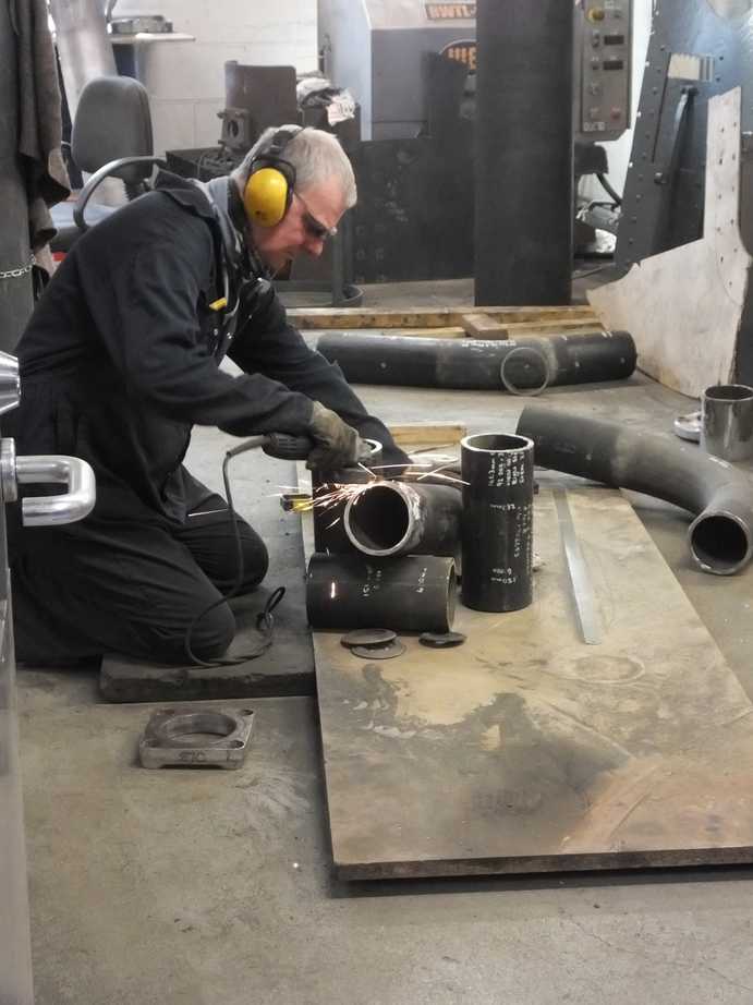
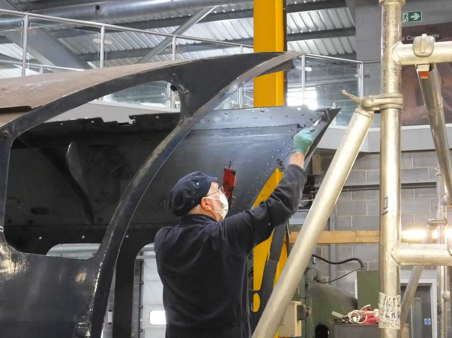
In the smokebox the fabrication of the RH steam pipe has begun. The pipe from flange to flange being all new material in 3 sections.
On top of the smokebox the condition and fit of the snifter sealing plates has been checked. They are OK for reuse as are the tapped holes in the wrapper. The snifter has been stripped down and faces prepared for gaskets. The old copper gaskets are suitable for reuse and have been annealed. New studs have been purchased to mount the valve, with a special stepped stud being made in a volunteer workshop. Due to wear and other damage the snifter valve top plate has had to be refurbished with the manufacture of a bronze bush to correctly locate the moveable valve. Meanwhile we are in the process of purchasing spare snifter valve components as they are subject to heavy wear and damage.
In the firebox the last grate support beam has been fitted. The drop grate was fitted and the end of the drop grate shaft fitted on the correct square for the linkage that goes back to the cab. Initially the grate fouled the front of the ashpan plate but when adjusted to it’s normal operating position it is now clear. However the drop grate did still foul 2 of the front grate support blocks fastened to the firebox foundation ring. When photos and the LNER drawing were consulted it was found that the 2 in front of the drop grate vary from the others around the foundation ring to allow the drop grate to clear. The blocks fitted were the same as the others so were removed and modified. They are now refitted and the drop grate operates correctly. The linkage in the cab has changed and it was found that we could not reproduced the ex service assembly and get full travel. This will be examined.
New pipe has been obtained for the ashpan sprinkler. The new pipe will require shaping, drilling and new mounting brackets fabricating. This work has started.
When the ashpan hopper door was tried it was a little tight. This was eased by the addition of a shim under one of the hopper shaft bearings.
A new pin for the trailing end of the damper reach rod has been made and fitted.
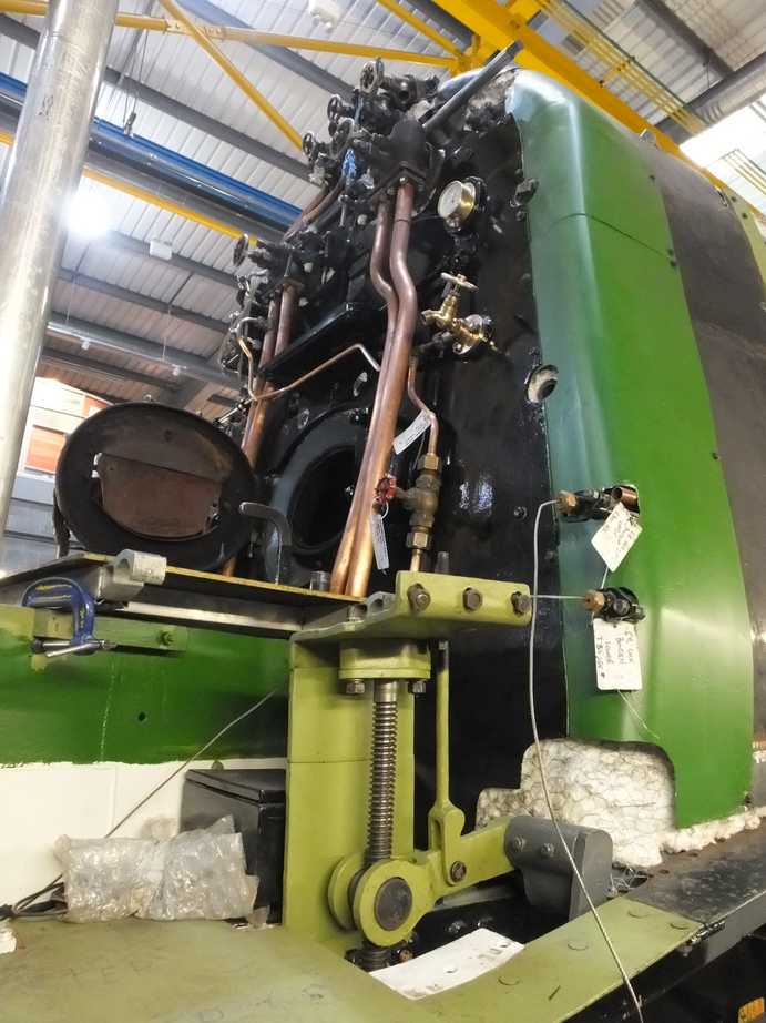
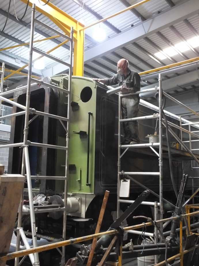
Work to repair and refit the boiler cladding continues. Some of the access doors have seen further preparation for painting by needle gunning. The shield that fits behind the mechanical lubricators and fastens to the cladding has been cleaned and fitted. All the boiler bands have now been painted to top coat on their inside surfaces to ensure maximum protection from corrosion.
The inside of the next cladding panels to be fitted have also been painted to top coat. The cladding panels either side of the steam dome cut out have now been fitted and the next trailing pair are ready to fit. The left panel with the steam dome cut out is all new whereas the right has a new bottom roll.
As the panels are fitted the footplate beneath the panel has been repaired and painted, same with any crinoline defects. The gravity sands conduit under the left cladding required further securing and a new bracket was fabricated and welded in place.
The right cylinder cladding has been fitted.
There’s a lot of painting going on at the moment. Amongst the items painting or painted are the tender filler cover, valve chest covers and valve guides, tender top check valve support bracket, tender trailing bufferbeam, shovel plate fabrication, loco brake gear, backhead corner cladding, tender corridor canopy. The inside of the cab is being painted with only a section of the roof not yet up to undercoat.
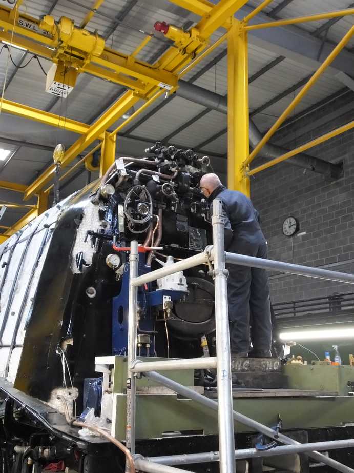
The installation of the loco pipework makes steady progress under the leadership of our Piping Team Leader. The steam supply from the manifold to the air pump governor has been fitted, with the pipe in the cab being lagged.
The ashpan sprinkler valve and cab pipework that is taken from the slacker pipe and runs from the right injector delivery pipe, has been refitted.
The small pipe runs from the air pump lubricator, to be relocated in the cab, to the air pump have been part ran in.
The atomisers have returned from contractors who were satisfied with our refurbishment so didn’t actually do anything to them other than examine them. They have now been refitted and the oil inlet, outlet and steam pipes refitted. The atomiser nozzles that fit in the cast iron stub steam pipes have been trial fitted and the atomised oil pipes ran to them.
The atomiser isolation valve has been remounted on the smokebox side. It has been refurbished and the hole in the smokebox had to be enlarged to get it in. The valve gives another fixed point to run pipes to.
The steam pipes to the steam sand pipe nozzles have been refitted. One connection was unsatisfactory so the pipe was re-ended.
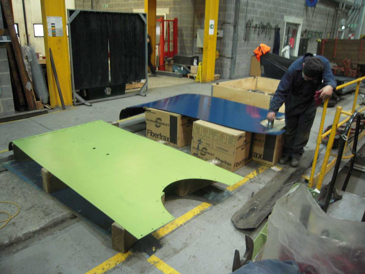
Also in the cab, the fireman’s heat shield has been rebuilt. A new plate was made and bent up, and the assembly is now being painted.
The large diameter vacuum train pipe from the ejector has had a new air ministry joint cone made.
The brake ejector steam supply pipe has been put up on to the manifold. This will help with the ongoing refitting regulator cross shaft assembly as this pipe crosses close to the shaft. A new regulator stuffing box gasket has been obtained and after a little filing fits satisfactorily to the stuffing box. The cover has been tried on but difficulty was experienced in getting the cover to close up correctly. An examination of the dimensions of shaft, housing and cover showed that the internal boss on the cover was just fouling the shaft. The boss has now been skimmed.
In the tender corridor all the brackets are now fitted for the mounting of the cods mouth door key, hopper lever and drop grate handle. The welds on the inside of the corridor roof are being ground back mainly for cosmetic reasons. The tender team have also fabricated a new shovel plate to replace the ex-service that was wasted beyond further use.
To access the back corner inside the tender tank one of the baffles is unbolted along its bottom edge and bent sufficiently to wiggle through. It was decided to make the baffle removable by cutting at the top and providing a bolted joint. This has been completed and will make it a lot easier to access the tank for maintenance.
The tender vestibule door has been descaled and filler applied, and can now be repainted.
The tender vestibule spring cover mentioned in the last report could not be fitted as it fouled bolts holding new plate at the back of the tender. The holes are now being tapped out and new screws fitted which will allow the cover to be fitted without modification.
Two new lower vestibule support rod bolts have been fitted. We had put new bolts in here but they turned out to be just too short when heavy duty spring washers were fitted. The bolts are mounted with nuts on top so it they were to work loose they could just fall out. The latest version have also been made a little longer and provided with cotters as a back up to the spring washers.
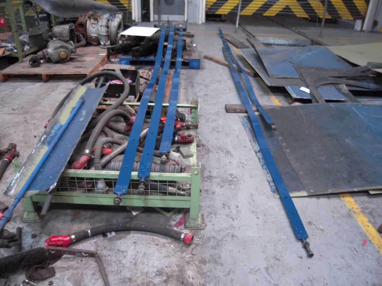
On the outside of the tender the new streamlining on the right side has been filled and sanded.
The tender front conduit run has been planned. The conduit has now been fabricated and is being painted prior to fitting.
The GSMR rack is being fitted in the tender vestibule.
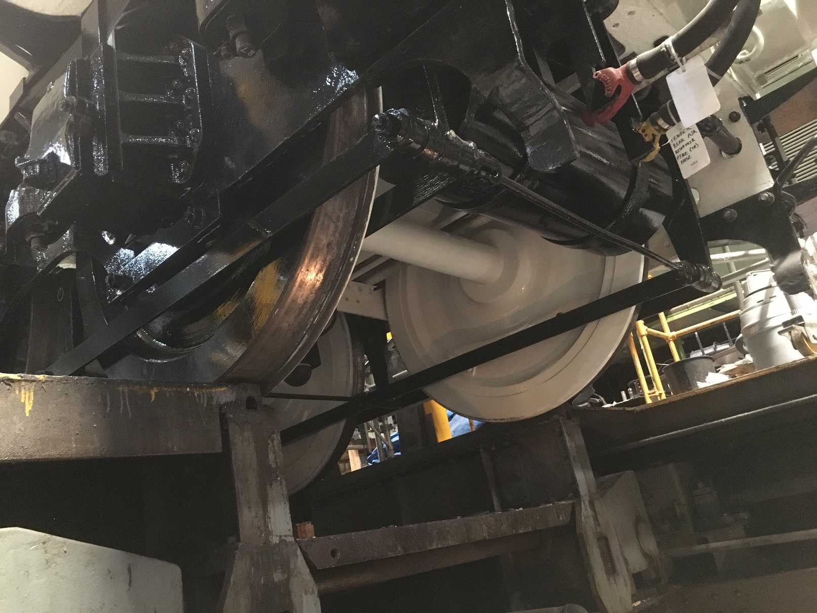
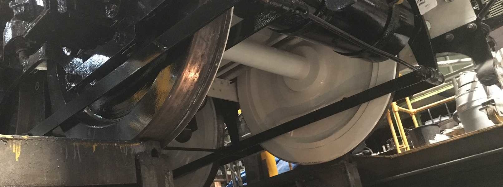
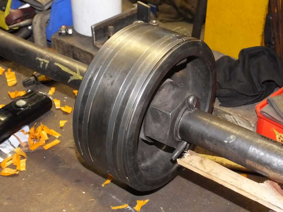
The loco and tender wheelsets have been ultrasonically examined by contractors. All have passed test.
The contractors preparing the design of the CET (toilet retention tank) have submitted a first draft of the completed design drawings. We’ve made a few observations and returned the drawings to the contractors. Copies of the drawings of the brackets that secure the main tank to the coach have been forwarded to the coach overhaulers and there is sufficient information for them to start manufacture of the brackets.