Weeks commencing 5, 12 and 19 April 2021
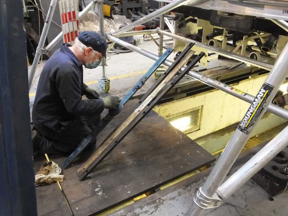
The trailing loco brake hangers put up in the previous report, are secured on their pins by slotted nuts. The old nuts were reused but were not slotted so these have now been machined to match the pins and the arrangement on the original drawings. Large washers are also required and these were machined from new material again to the original specification. The nuts are now pinned in place and allow free movement of the hangers.
The upper leading brake pulls have been delivered to the forge to have their length adjusted.
The brakeshaft bearing bolts have now been washered and cotterred. There’s steady progress working through cottering the brake gear.
The leading brakeshaft bearings grease nipples have been fitted. Historical damage to the left side oil hole meant a special fitting had to be made and pressed in for this side.
The last of the leading valve guides, the middle, has now been finish machined and has been assembled in place. The matching valve crosshead has also been machined to suit the guides. This has taken a couple of iterations due to the valve cover introducing a slight misalignment of the guides, which is easier to accommodate by machining the guides and crosshead rather than the cover.
When the valve crossheads were fastened hard to their spindles this introduced slight movement of the crossheads. This has required some re-shimming of some of the base guides, under the crossheads. As new shims are to be made for under the guides that fit over the top of the crossheads, some new shims will be made for the base guides. The material is now on order and will be surface ground by the Engineering Team.
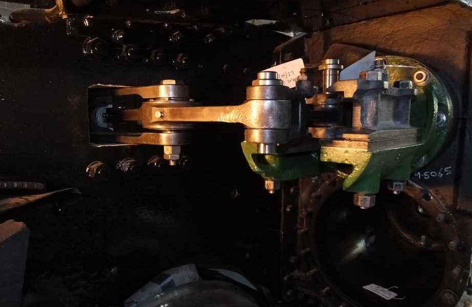
The 2:1 and 1:1 levers have been assembled and tried in place. It was found that the right end of the assembly was low and did not want to fit into the short link from the leading valve crosshead. On the other side of the engine the rod the lever was high. This indicates that the vertical height of the valves and rods are probably OK, but the 2:1 lever is leaning at its pivot. The assembly was removed from the loco and the bushes fitted into the loco frame that the 2:1 lever pivot fit into were measured. It was decided that the pivot bushes should be renewed and measurements indicate that this should level the 2:1 lever. The lower bush has now been made and fitted.
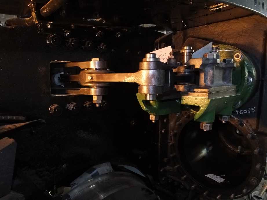
The lever assembly had to be removed anyway to allow the 2:1 lever to be painted and this is underway.
The middle trailing guide bush that fits in to the middle trailing valve cover has also been fitted. It is secured by 3 studs and nuts, and prevented from loosening by split pins. This assembly is complete.
The left union link has now been adjusted and fits easily onto it’s crosshead and combination lever with no binding.
Work continues on the lower slidebars at their ends where assembly has led to them closing, reducing the clearance for the piston crossheads. The sidebars have been carefully dressed to even up the clearances. The right side has been signed off by our CME.
The 6 drain cock reliefs and the 6 main cylinder end relief valves have been overhauled and set, being completed by one of the Engineering Team at home. So no more mopping up in the home workshop.
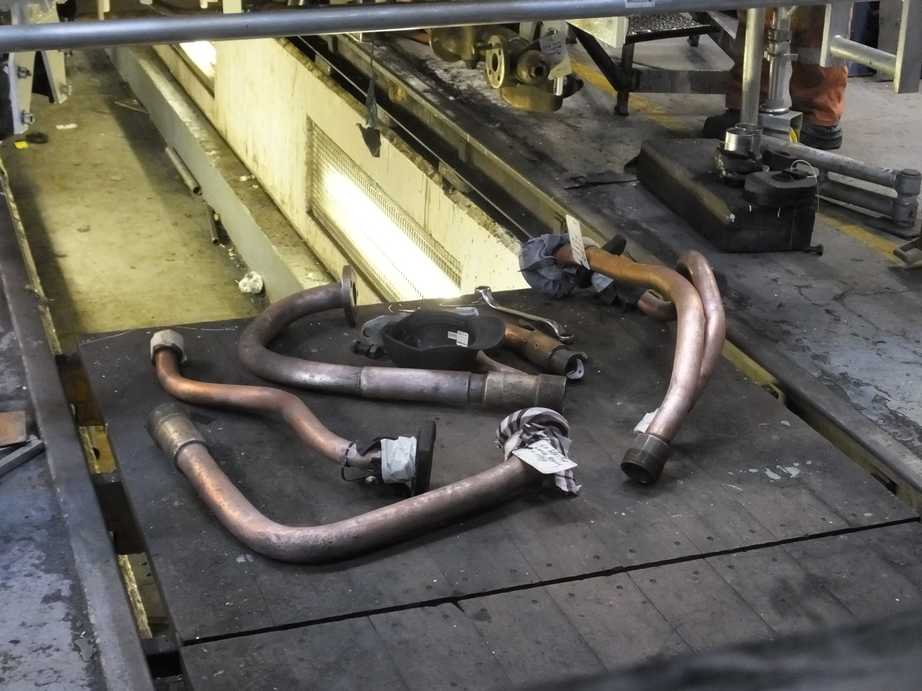
The left and middle steel main steam pipes are now ready for final welding. A decision was made to renew the right pipe and the existing pipe was tacked in place to provide a pattern for new sections of pipe to be made. The right pipe assembly was then taken to pipe bending contractors.
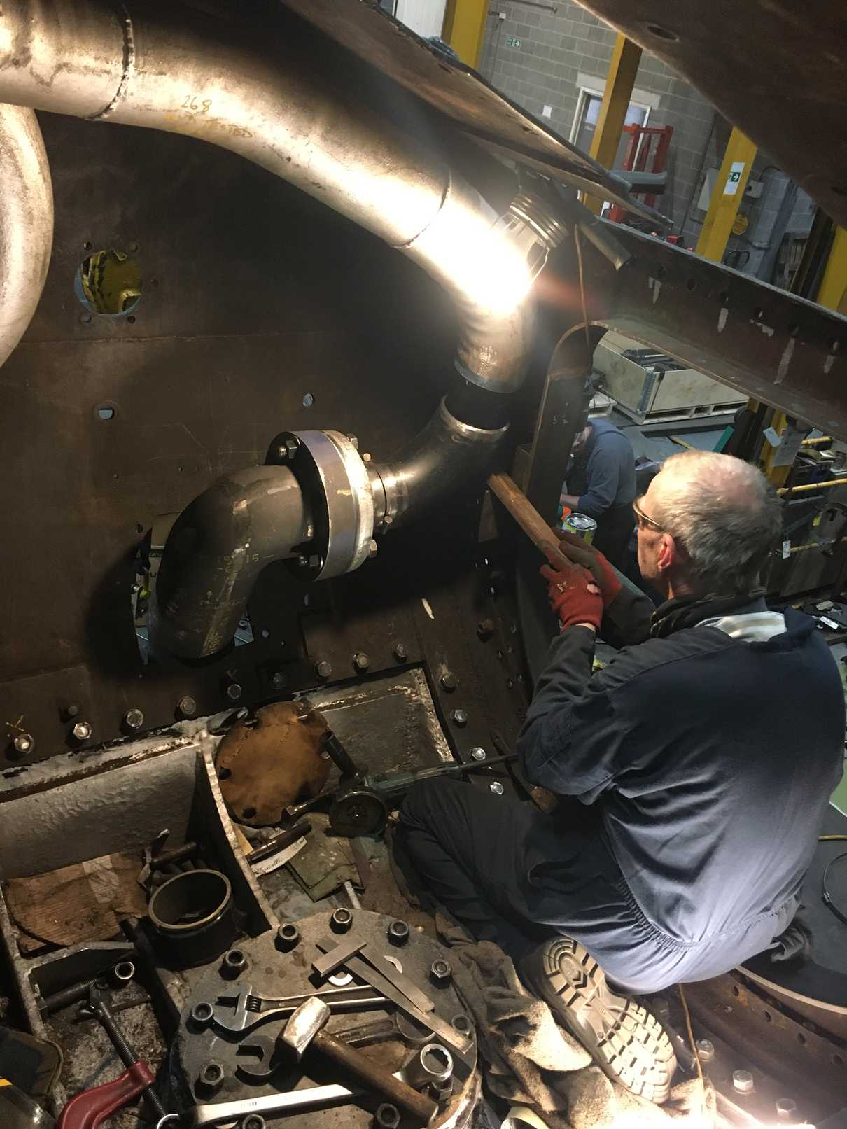
The left pipe has had to be renewed into the leading flange. This required the old pipe to be machined out of the existing flange.
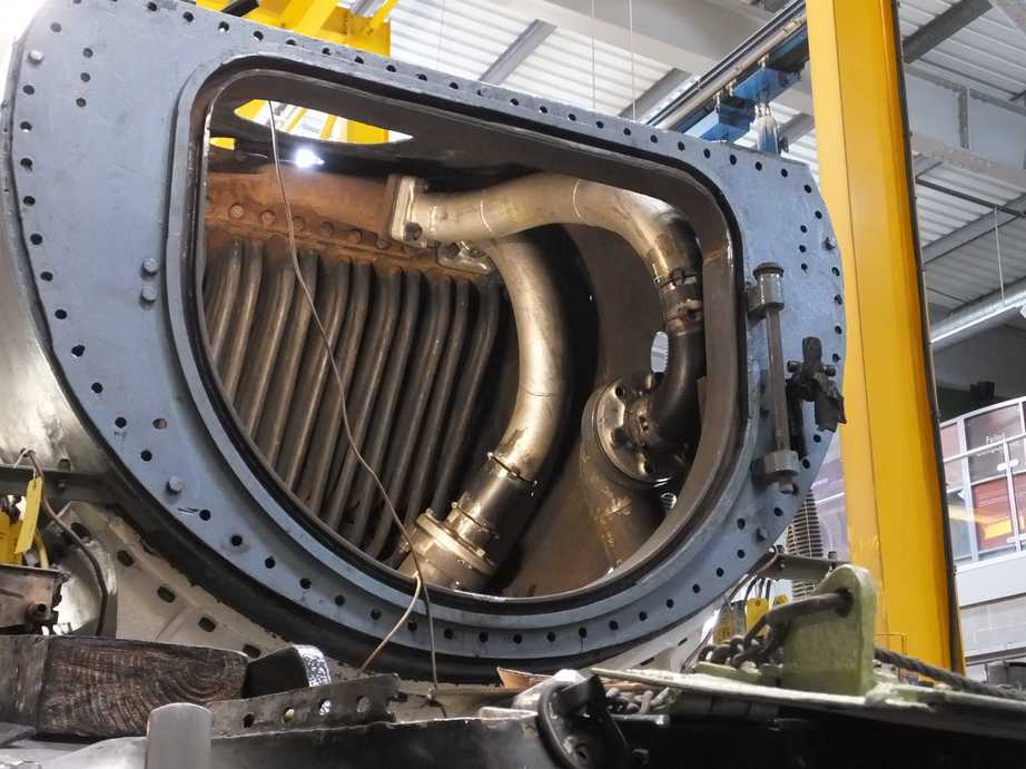
Our boiler insurer visited York to see the fabrication of the pipes so far and to discuss the boiler and our plans for hydraulic testing and steaming. The insurer and our mainline certification authority, who also visited, are all happy with the pipes, boiler and our future plans.
On the sides of the smokebox the drilling and tapping of the superheater header cover plate securing holes has been completed. The holes were a mixture of threads and some damaged. The holes were welded up as required, re-drilled and tapped out to a common size.
On the tender the vestibule bellows has been fitted. This involves dozens of small screws and backing pieces being fitted to secure the bellows to the tender. Some strips are wasted so new have been made.
The vestibule lower support brackets have also been refitted after it was found necessary to skim the lower support packing pieces.
The vestibule floor has been filled and levelled with cement.
The top of the vestibule connection is pushed out by a leaf spring pinned to a bracket on the tender top. A new pin has been made, but when fitted it was found the pin sits at a considerable angle. At some point the plate has been replaced and the holes for the pin are misaligned. The top plate has now been cut off and a new piece of plate will be fitted to align with the lower hole on the tender top. We are lining up with the lower hole as this one goes through, what looks like original platework.
At the back of the tender, and on the upper sides, prepping for painting is underway.
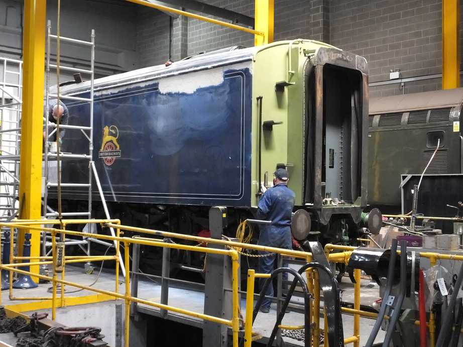
The final patches of paint around the vestibule have been needle gunned off. Filler has been applied along the top of the upper beading, at the back of the tender and along the new streamlining where welded to the tender side. Primer is being applied.
On the tender front the GSMR enclosure was put up and a new protective bar fabricated and welded in place. This will protect the edge of the enclosure from the fire irons that lay across the front of the tender.
The fire iron brackets have been finally welded in place, and cosmetic rivet heads added to them and they look really good. The holes for the the tender number plate have been drilled through as have the holes for the GSMR mounting bolts. Beading has been added to the new roof section above the corridor door. A new catch plate had been made for the corridor door catch.
The ashpan door operating lever and the cod’s mouth key are kept on brackets in the tender corridor. With the renewal of the corridor upper sections the brackets have to be replaced. New brackets have now been made. The key was originally kept on the tender front and it was considered to return it to the original arrangement as we still have one of the original brackets, but we thought that if someone was to take it we’d be unable to open the front of the loco, so it’s better out of sight.
The steel floor sections at the front of the tender have been drilled and tapped to accept countersunk screws and fastened down.
The main intermediate drawbar machining continues off site by one of our Engineering Team volunteers.
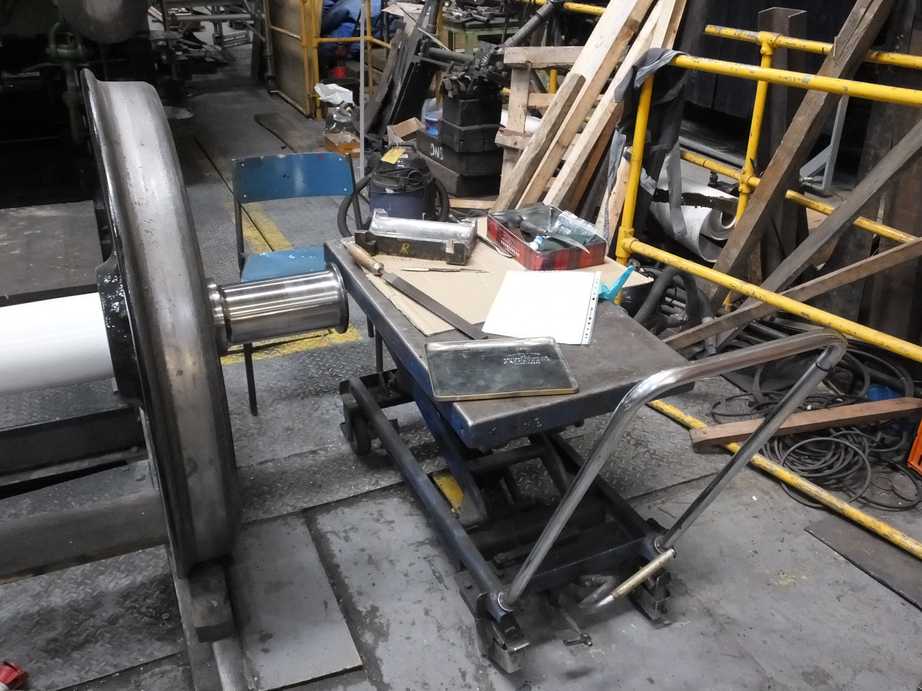
Scraping of the Cartazzi bearings has begun.
The cab interior is now being cleaned down and prepared for painting. Patch priming has taken place. The window runners were taken apart and some of the wood runners look in need of replacement. There are some sections of the brass runner sides that look to have either broken off or been cut away. This will need to be looked at.
The cab roof centre section has been removed and needle gunned and is now prime painted.
The piping installation on the tender top has been completed. A support bracket for the air delivery non-return valve is required, which won’t be completed by the pipe fitting team. The system is now being readied for pressure testing. Our Piping Team have done a lot of work improving the tender air system arrangement.
A rubber guard was added to one of the copper pipes next to a steel water filler pipe at the bottom of the right tender top drain as they are close. All the pipework is well secured so there should be no contact but the rubber was added as a bit of insurance.
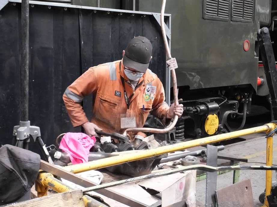
A start has been made on the assembly of the injector pipework under the cab floor. A lot of work has been done in this congested space so the first step is to assemble without pipe joints to ensure there is clearance on the pipe runs and no clashes.
The loco front steam heat cock was pressure tested satisfactorily after the pressure test equipment was returned after the completion of the relief valves. The tender cock is nearly there with just a dribble on the lower cap, where you would think it would be easiest to seal. The loco front cock has now been refitted to the loco.
The drip valve in the steam supply to the governor was fitted after a fitting was specially machined to raise the valve as high as possible to reduce the chance of damage in traffic or being a hazard when working beneath the loco.
The atomisers have been previously stripped and examined by us and appear OK, but as they are a critical piece of equipment it has been decided to have a contractor give them the once over. They have now been delivered to the contractor.
The gravity sands Bowden conduit has now been fastened to the new footplate mounted securing bracket. Now secured the left boiler cladding can be fitted over it.
The leading right boiler cladding plate received some final dressing around the access door hole and is now ready for painting and final fitting, much to the horror of the piping team who see access to their oil pots being much reduced.
On the left the leading boiler barrel and next trailing cladding panels are now fabricated and temporarily mounted on the engine and have been marked for locating the cutouts for their access doors. They will be removed, door apertures cut out, painted then refitted for the final time. It is not planned to replace any other full panels but other panels still require repair.
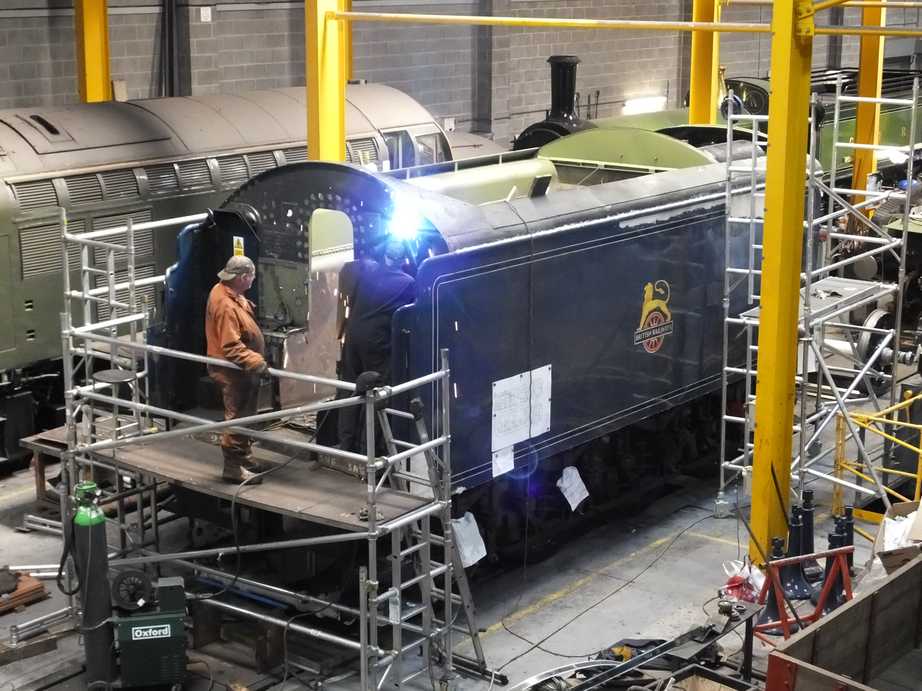
Work has now restarted on the electrical installation on the loco as our Electrical Specialist has now returned to work after Covid shielding. It was decided that refitting the AWS/TPWS conduit that runs the length of the left side of the loco should be the first job tackled. This runs over the left cylinder cladding and footplate angle, so in preparation the angle was painted to top coat. Then the right hand cylinder lagging and cladding was fitted. The conduit brackets were retrieved from store, these being repainted before being put in store some time ago. The conduit run was then installed. The cabling has also been pulled through but requires termination.
While painting the left footplate angle the reverser reach rod was also painted.
Quotes for the new section of handbrake shaft have been received and the order placed. The old upper handle section has been given to the contractors and work is underway in the manufacture and assembly of the handbrake shaft and nut.
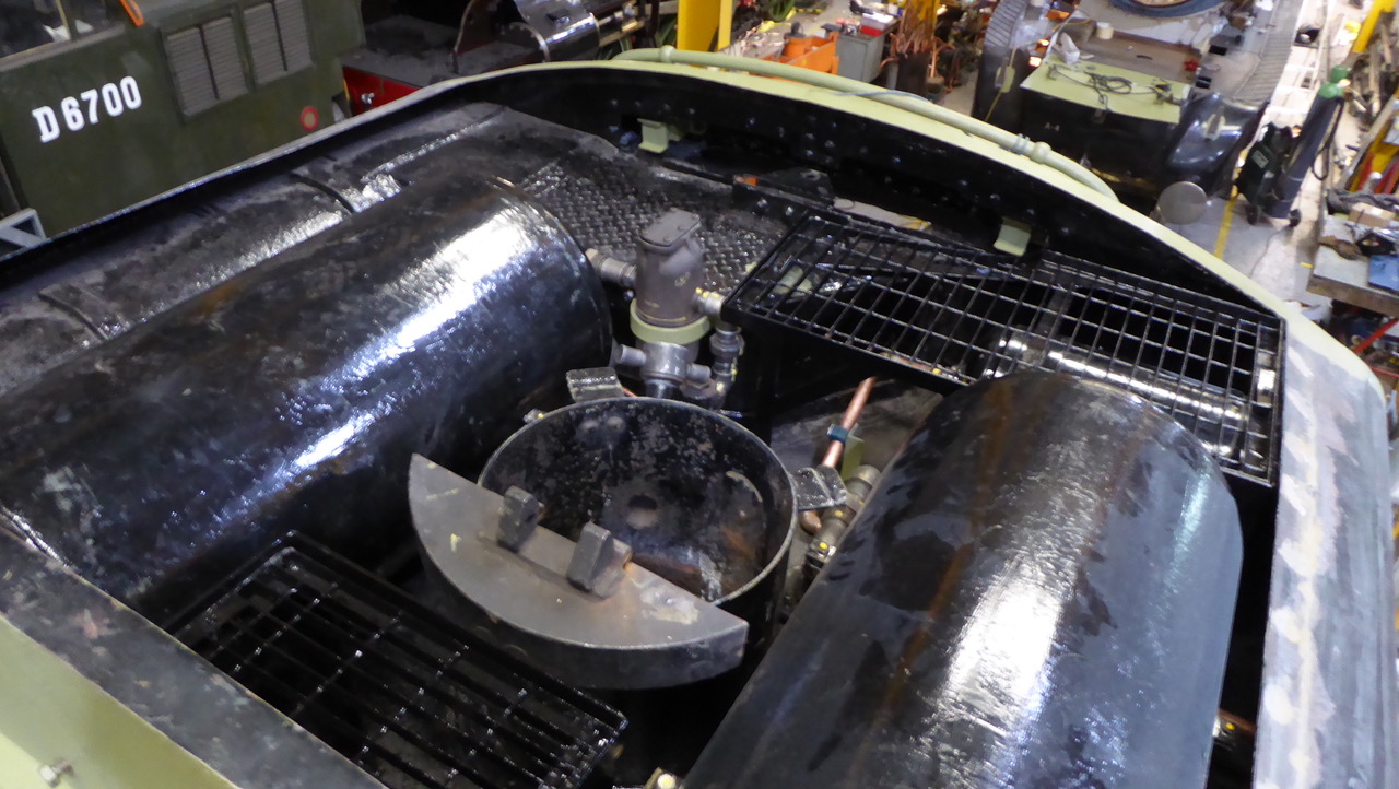
The pipe connections at the boiler manifold have all now been checked. The new cone for the steam heat valve has been fitted to it’s pipe and a recovered cone fitted to the pressure gauge pipe as the original was beyond further use.
It was noticed that the air pump shut off valve appeared to be in the wrong place on the manifold! There are near identical valves at each end of the manifold but the fit of the cones indicated that the valves were wrongly positioned. This was confirmed from photographs looking at the minor differences between the valve handles. The valves have now been switched over. The dressing of the boiler mating face for the manifold was completed to our fitters exacting standards and the manifold fitted.
The fitting of the cladding around the manifold and the top corners of the backhead cladding was completed to allow the fitting of the manifold.
It was attempted to fit the cab warming shelf but we couldn’t get it to fit as the cladding stood too far off the boiler. A plate was made to pull the backhead cladding toward the boiler and after a twang the plate moved in to where it should be and the shelf is now fitted.
The reverser indicator is now being fitted to the backhead cladding.
The drop grate cab mechanism has been fitted to the cab floor plate.
We have had a meeting at the coach overhaulers with the contractors, toilet tank designer and our TOC who obtain the funds for the work from Network Rail. The design should be completed soon.
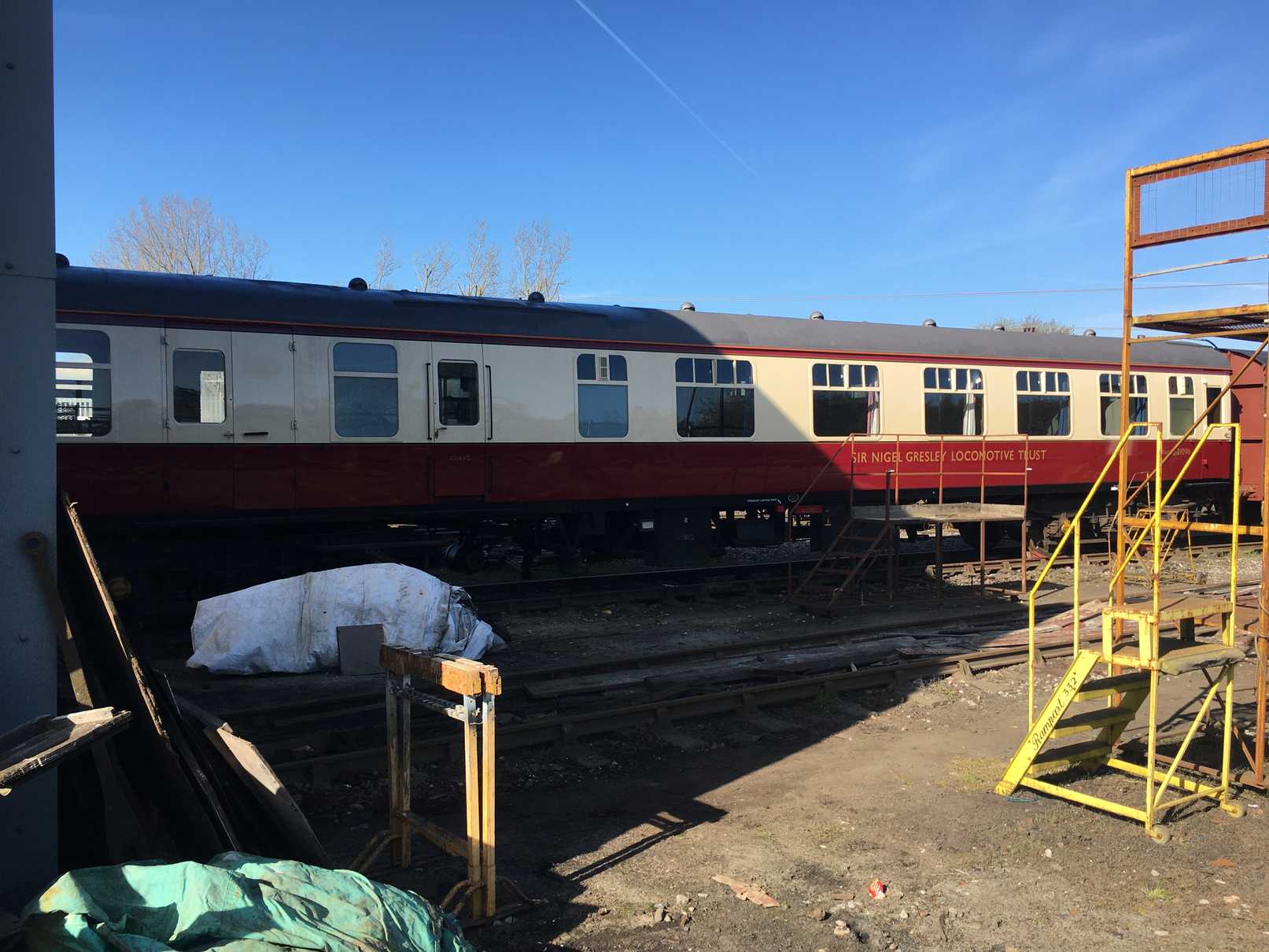
The coach looked really good in the sunlight and seems to have weathered the winter well. One of our volunteers has kindly donated wash wax and polish for the coach, the best types in his experience of looking after a support coach.
The “new” coach air tank has been tested and I’ve been told it is a good one.