Weeks commencing 9, 16 and 23 November 2020
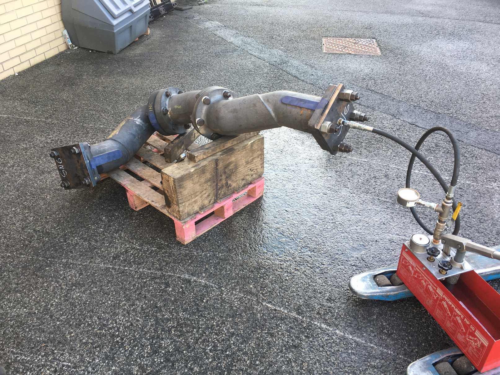
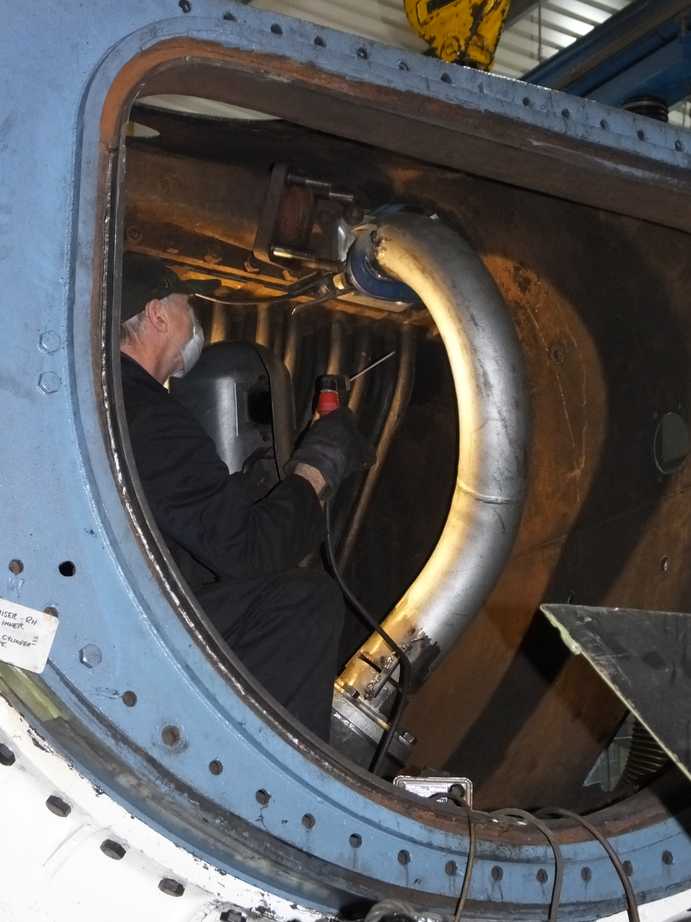
The volunteer piping team have completed the new steam supply pipe run to the air pump. The pipe has been hydraulically pressure tested. It is now being lagged and finally fitted.
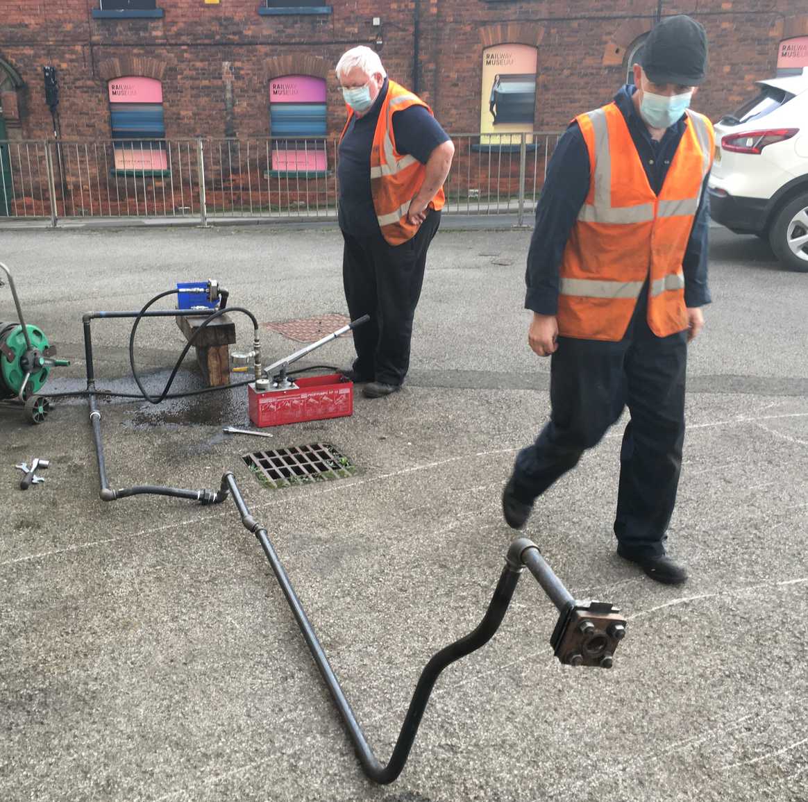
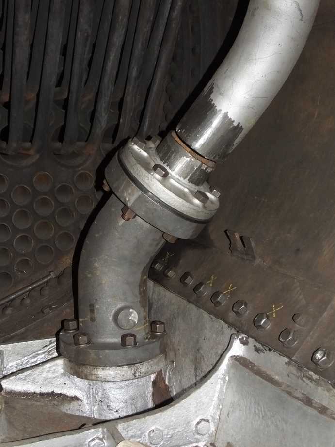
With the completion of the air pump steam supply pipe, the team have revisited the tender top air system. One of the large air pipes rerouted up one of the drain pipes has been cut to length and the fittings for linking to the air tanks are being prepared.
New cone ends for the 1/2″ steam supply pipes to the atomisers have been made and have been fitted. All these cone ends are made to the LNER drawing dimensions and replace a wonderful variety of worn cone ends probably made piecemeal over the years.
A new end, threaded 1-7/8″ for the steel smokebox atomiser steam supply stub pipe has been machined.
The remaining leading lubrication pipes have been annealed and a batch of new 3/8″ cone ends machined.
The Cartazzi brasses are now with contractors for machining.
The new Cartazzi oiler pads have been collected from the manufacturers.
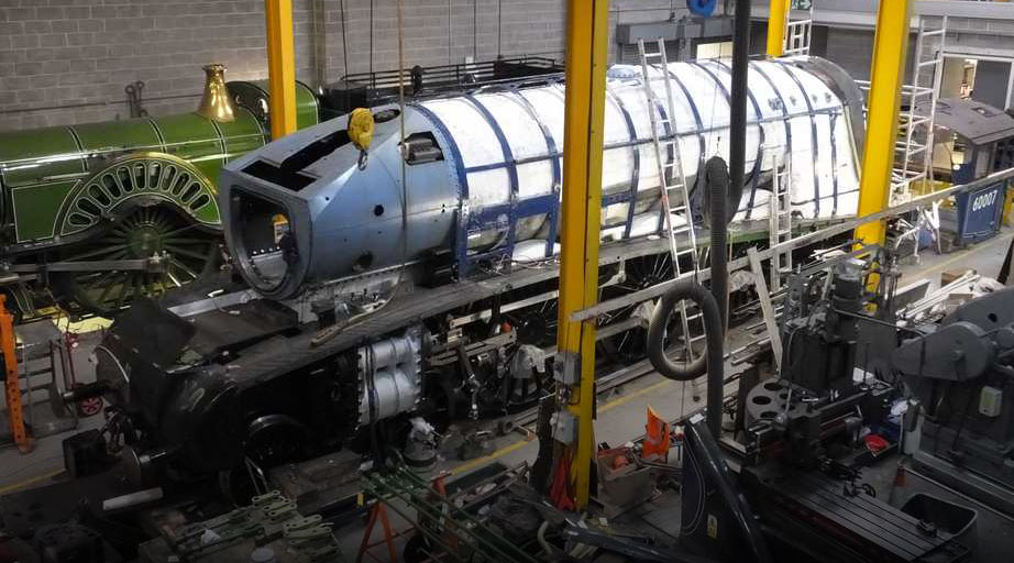
The cast iron steam pipes have been pressure tested after their fit in the smokebox had been checked. The pipes were refitted in the smokebox and the steel pipes that connect the superheater to the cast iron pipes tried in.
When the pipes are finally fitted they are fitted with lens rings that are used to seal the pipes and to allow slight misalignments to be accommodated. The specification is for there to be a 3/8″ gap between the pipes so misalignment is sure to be taken on the lens ring. To represent this gap plates have been used, sandwiched between the end flanges of the pipes.
As the cast iron pipes are new, the existing steel pipes don’t quite meet the cast irons ones so the steel pipes require modification. This is done by cutting the steel pipes and fastening their ends at the superheater and on the cast iron pipes. The gaps are then bridged with steel pieces to hold the pipe to its new shape. The pipes will then be sent to contractors for welding and, where necessary, new sections of pipe will have to be added. This is difficult and heavy work.
The left and middle pipes have now been dealt with. Before the pipes are sent to contractors for welding our boiler insurers have requested that they see the welding procedure documentation. This request has been sent on to our usual welding contractors.
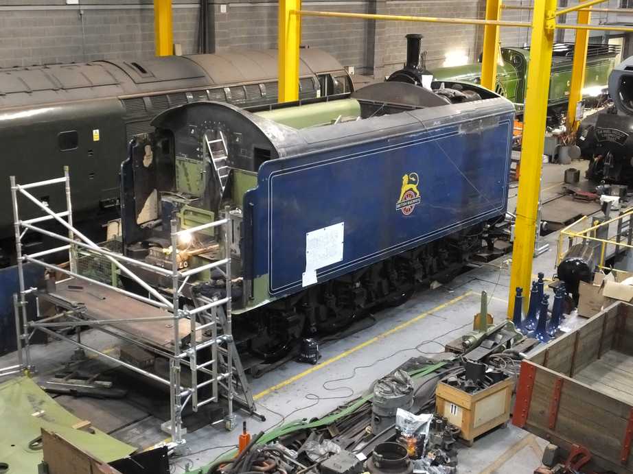
The tender floor supports have now been fabricated and fitted to the tender tank floorplate. The water gauge connection below floor level has been cleaned of scale and prime painted in preparation for receiving the gauge.
The small canopy at the end of the corridor has been fitted. Where it meets the tender side, the top tender streamlining and the tender front plate have also to be finished. It’s quite a complicated coming together. I don’t think the boiler-making team are going to enjoy work where they can’t swing a big hammer or get max-amps on the job.
The rivet heads on the front of the tender front plate that secure the coal door frame have been ground down. There’s more to do, but the plate will be left flush when completed.
The speedo crank on the left trailing coupled wheel has now been fitted.
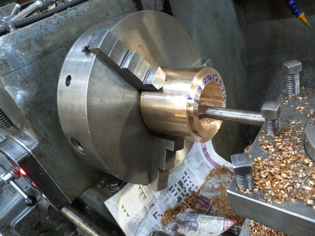
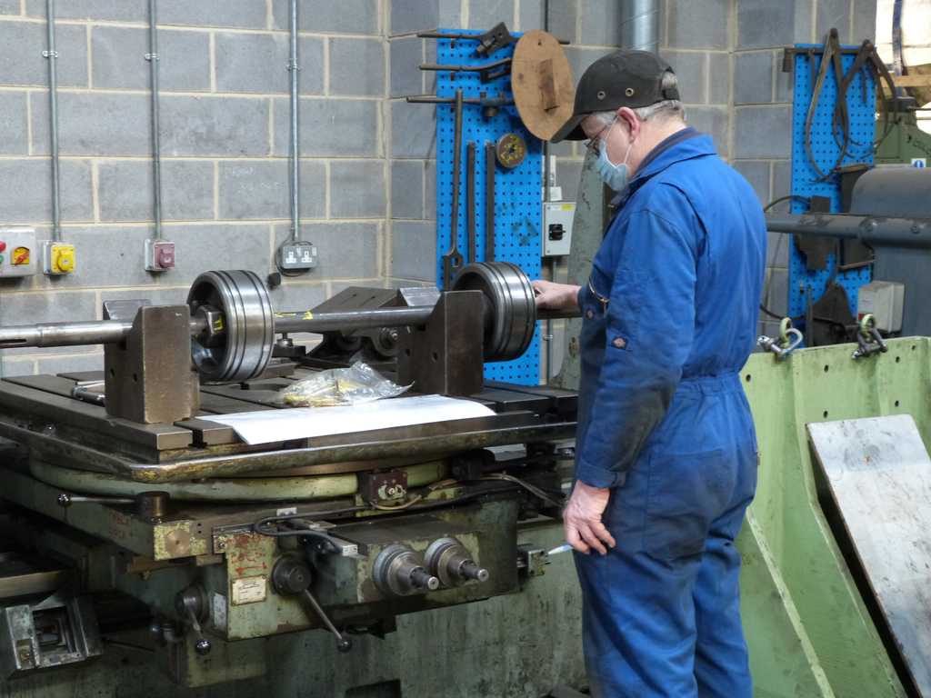
The little end bush machining continues. They are complete except for the slots for the oiling felts, which will be done off-site by one of our volunteers. The oiling rings that fit on the ends of the bushes have been roughed out. The keyways in the rod little ends and the ex-service keys have been examined. The keyways will be refurbished, as those in the coupling rods and big ends have been. It is most likely that new keys will also be required.
The reassembly of the valve gear continues. The outside valve heads have been put on their spindles in what should be their final positions. This required some machining of the central bosses of the leading heads to get them correctly positioned. The old head in this position was a middle head casting which has a differently dimensioned centre.
Just to ensure we knew what was going on, the dimensions of the valve, valve liners and distance to the valve crosshead were rechecked and this confirmed that the heads required modification. The leading right and left heads were modified and the assembly confirmed, as when on their spindles with the securing nuts tightened, the cotter pin holes in the valve spindles were correctly exposed.
The middle steam chest has been measured for setting its valve positions.
The height of the running surfaces for the valve crossheads is set with shims. New material was ordered and has now been ground to the correct thickness for the leading valve crossheads. These have been fitted and the heights to the valve spindles measured. This allows the dimensions for these valve crossheads to be finalised.
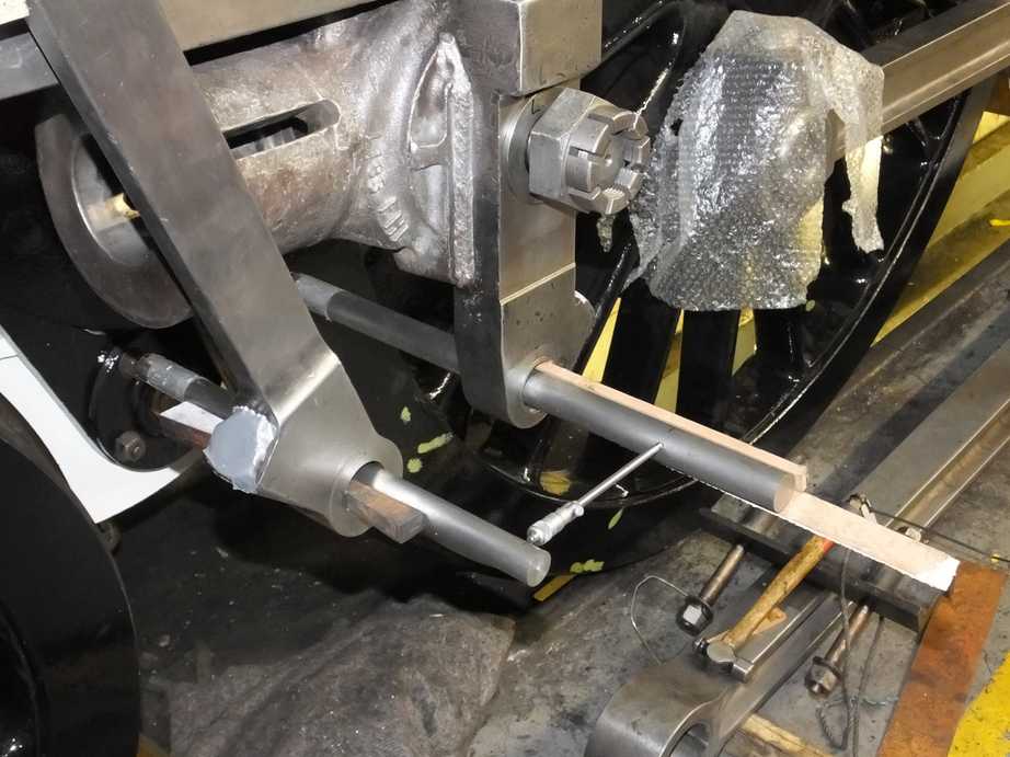
When we were happy with the valves, the union links were tried in position. We were aware that the left union link is bent. This was discovered during the fitting of the new motion pins. In addition, when the left piston crosshead was machined it was found that the crosshead sliding surfaces were not square to the drop link hole—probably to accommodate the union link. We are only talking thou’s, but that matters when the motion pin clearances are also thou’s.
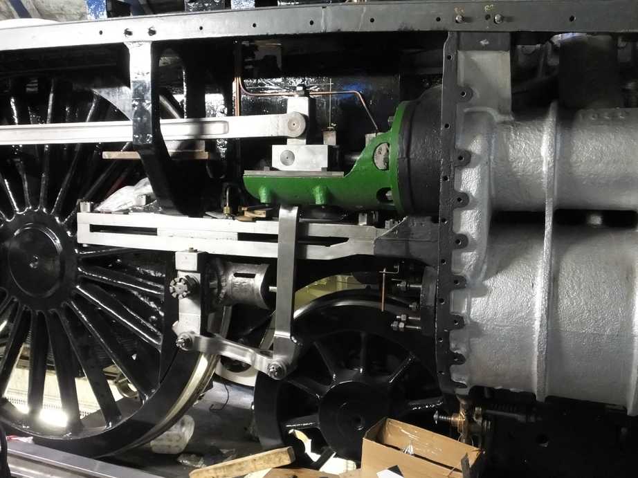
It has also been found that the swing of the combination lever isn’t exactly in line with the slidebars. This makes the union links tight on the crosshead and combination lever in parts of their travel. This all probably originates in the mix and match approach of Crewe when they used 60026 and 60007 parts. To free off the tight spots the combination levers have now been adjusted to a best position where their travel is free. The right is now fine for final fitting but the left union link requires attention to align the pin holes with those in the crosshead. This won’t be easy as the union link holes are hardened.
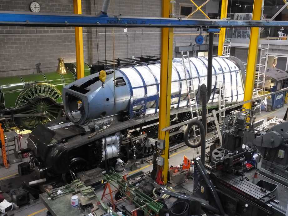
Work on the boiler cladding continues with the refurbishment of the right side sheets. A lot of work has been done over the last couple of weeks on cleaning, trimming back and treating corroded feather edges and prime painting. The boiler washout access “top hats” have been removed so that the concealed surfaces can be cleaned and painted. Some have been re-riveted back in place but there is more to do. The material for the new cladding panel has been ordered and is now available for collection.
Meanwhile the crinoline spine threaded holes have been cleaned out.
The new countersunk screws in the crinoline that hold the belly straps project out of their holes more than the old screws. The new screws are also hard so their tops have been ground to reduce the chance of them cutting in to the cladding sheets.
The right boiler handrail and knobs have been brought in to the workshop from store to be prepared before fitting.
Work continues on rebushing and pinning the brake gear. The pins are now complete for the lower brake pulls.
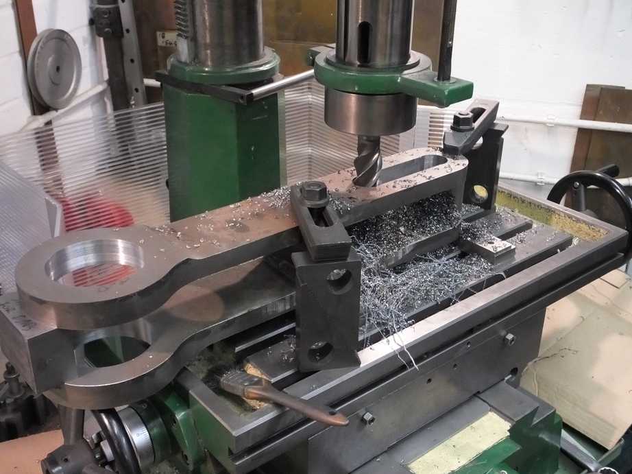
The new handbrake link has been finish machined. When the spacers put in for fabrication were removed, the assembly sprung, and it has now visited the jack and press and now complies with drawing. The link was then di-pen tested to ensure there are no surface defects and it is now ready for painting and fitting.
The new loco brakeshaft bearings have been cast and are ready for collection.
The assembly of the tender to loco drawgear continues. The spacer plates behind the dragbox are now in place, pinned so that when the eyebolt is removed they don’t fall on your head. They also take the weight of the eyebolt when in position so reducing further wear to the dragbox casting. The eyebolt required a new cotter and this has been made.
The large rubber spring that reduces the shock loading to the intermediate drawbar is now under scrutiny. We have obtained a copy of the original drawing for the spring so we have the correct loading and rate information for the assembly.
The intermediate drawgear side or safety links have now gone to contractors for heat treatment.