weeks commencing 19 October, 26 October and 2 November 2020
The tender coal space door frame has now been rivetted in place. This is the last major riveting that will be done on the loco.
The new battery box has now been fitted to the front tender bulkhead and welded in place.
The corridor had a small canopy projecting from the top. It was originally pressed to follow the corridor profile with a nice lip to it. Unfortunately the original cannot be reused, even though it might date from the original construction. It has been plated over numerous times to make up corrosion and is beyond further use, like the corridor roof we have had to replace. The original drawings were consulted and dimensions taken off the tender and a new canopy has been specified and ordered.
At the back of the tender the sealing done to stop the pitch leaking seems to have gone really well, so we’ve moved on to tackle the flow inside the vestibule space. A very unpleasant job cleaning this stuff out. It wants to stick to everything and only flows when your back is turned. After a week it looks like this has been successful so the area has now been given a final clean out and a coat of primer.
The upper vestibule support guides have been assembled and well greased and have been fitted.
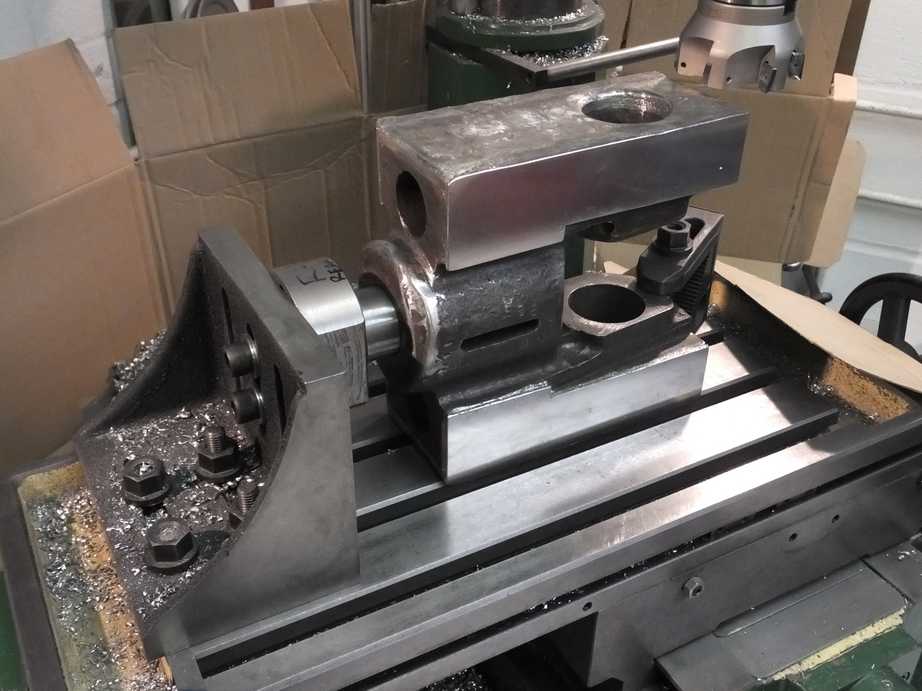
The plates in the back of the leading tender dragbox that the intermediate coupling fits through, were positioned and were tack welded to hold them in the correct position relative to each other. They have now been removed and the central square hole is being machined to give a good support to the tender coupling that fits in it.
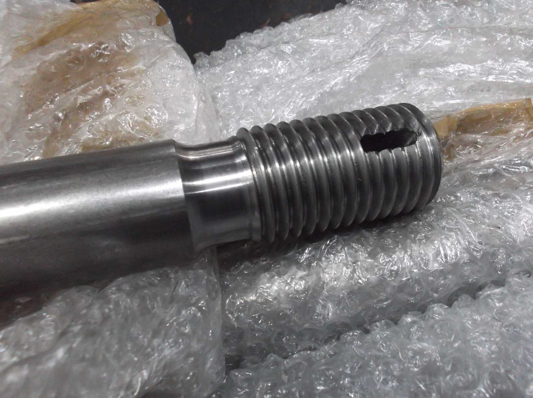
The new intermediate coupling side links have been collected from contractors and have had their edges ground back to remove the profiling marks and to remove any sharp edges. They were profiled oversize to allow this. Attention has now moved to the replacement of the main drawbar.
The safety shackle normally on the rear bufferbeam has been given it’s final inspection and is now painted in primer.
The fabricated handbrake link has now been collected from contractors. It now requires machining.
The cylinder covers have now all been inspected for defects. All are OK for reuse.
In the smokebox the superheater header plates put on to enable it to be hydraulically tested have been removed. One of the studs on the middle cover where the main steam pipe attaches was found to be wasted. The other studs on this flange look new and must have been renewed at Llangollen.
We decided that this stud should be replaced so it has now been removed. It didn’t come easy being in the top corner of the smokebox facing to the side. To get to it the stud in front of it had to be removed and after removal it also required replacement. Both studs have now been replaced with studs machined by the Engineering Team.
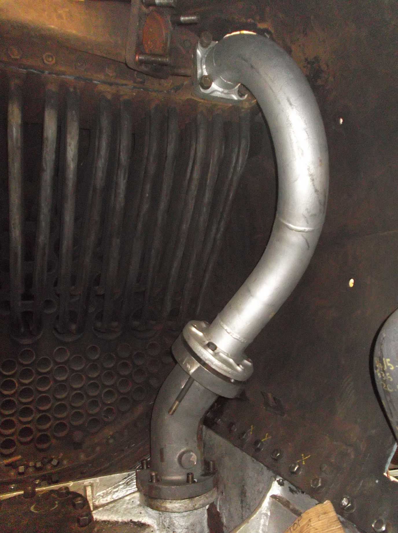
The stub pipes that connect to the front tubeplate that supply the atomisers and blower were retrieved from store and examined. Both sealing faces of the flanges have been refurbished to remove corrosion and to return them to flat. They both show corrosion to their other threaded ends, but the blower is suitable for further use. The atomiser pipe will require a new end machining then welding on.
New copper gaskets for the flange ends of the stub pipes have been purchased.
On the threaded end of the atomiser stub pipe a large diameter copper pipe goes to the atomiser valve that can be seen over the left nameplate. The valve has been refurbished and a new nut and cone end for the pipe was made. Unfortunately the new cone end doesn’t fit the existing pipe as it is not to original specification, so a new cone will have to be made or a new copper pipe made up.
All the new cast iron steam pipes have now been tried in place and the middle steel pipe that connects the cast iron pipe to the superheater has also been tried in. The first fit of this pipe is surprisingly good.
The cast iron pipes have now been removed and are being prepared for pressure testing. Seals for the test and a couple of end plates have been made. After testing they will be drilled for their lubrication connections.
We need new loco brakeshaft bearings. They are made from cast bronze, but could be made from bar material. I have talked to other similar loco owners to see if they had patterns but I couldn’t find any. Quotes were received for suitable bar and for castings, and surprisingly the cheapest way of doing the job was to go for castings. The order is now placed and I plan for the castings to be machined by our volunteers.
Work continues on the loco brake gear, with the brake pull arrangement that goes between the brake beams mostly done. It had previously been done with different sized pins, perhaps to take up wear in bushes without replacing the bush, or when done piecemeal, as the LNER/BR drawing shows all the pins we are working with to be the same size. It has been proposed that some of the larger sizes are retained to reduce the amount of work we have to do, and this is acceptable in some locations where it would not cause confusion when stripping or assembling the gear. Some work has been done to the links that connect the brake cylinders to the leading brakeshaft but work is concentrating on the lower links between the beams.
The purchase order for the machining of the Cartazzi brasses has now been placed. We were asked for a journal disc to be made for the new bearing and this has now been made. Unfortunately the contractor has not been able to start machining them yet.
The liners for the trailing Cartazzi horns are now on order.
The Cartazzi gauge/jig used to ensure that the horns are parallel and spaced equally was retrieved from our Grosmont store. This will be used when the the new liners are fitted.
The new Cartazzi hangers have now been slotted and the radii at the end of the threaded sections finished, all by an Engineering Team volunteer. The spare has been painted in primer and has now been put in to store. The others are staying in the workshop to be fitted.
New Cartazzi oiler pads have been ordered.
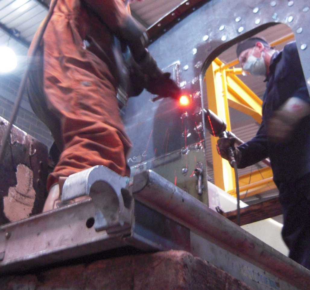
The installation of the steam supply pipe to the air pump continues. A very tidy hole has been cut through the footplating and the full pipe run is now in place. Just some minor tweaking to complete.
In the same area as the air pump, good progress has been made fitting the new throatplate cladding.
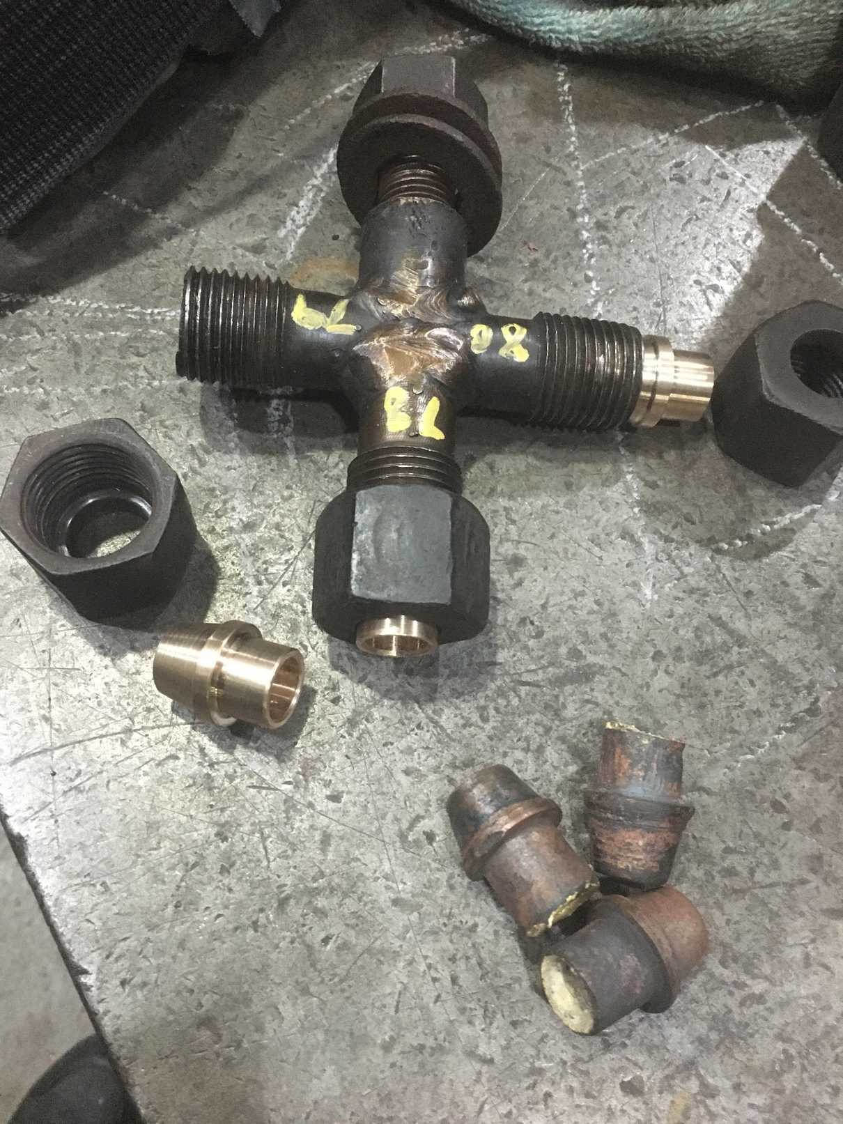
The atomiser pipework around the outside of the smokebox has been revisited. The steam supply pipe splits at a tee and goes off to 2 banks of atomisers, one either side of the smoke box. This is at boiler pressure so the joints have to be good. It was decided that the old pipe ends require renewal at the tee and new cones have now been made.
>The measurement of the valve spindle and guide offsets has now been completed. The leading valve guides require machining to return their surfaces to be parallel to the valve spindles. These are now being trued up and then will be remeasured before final machining.
The measurements taken have allowed the specification of the shims required to set the lower valve guide surface height. Drawings have now been prepared for ordering the material.
The leading valve crossheads have now been re-metalled and require collection from the contractors.
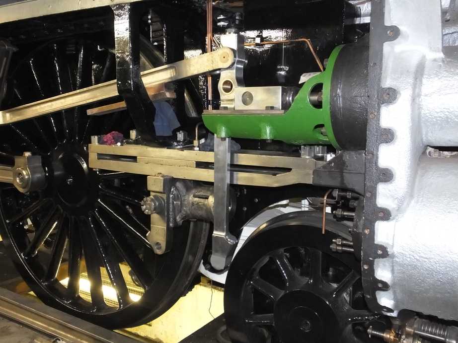
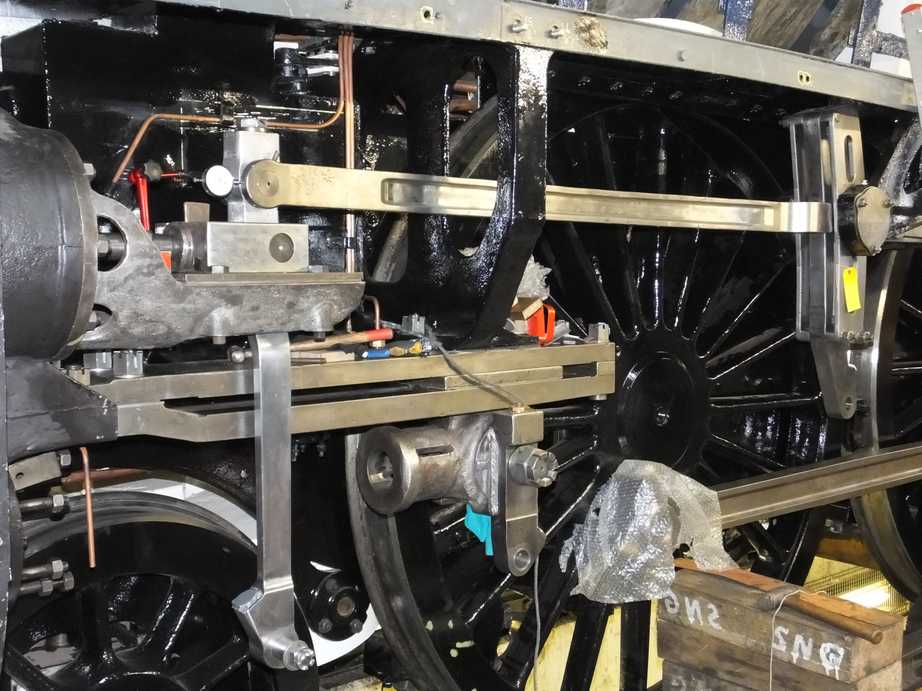
Both valve gear combination levers have now been fitted. The joints had been previously reamed to suit the pins but were intentionally left close. We knew that final assembly in place would probably require some easing and this was the case. Some minor adjustments were required but both combination levers are now a good fit at the radius rod and in their valve crossheads.
With the combination levers fitted the mid gear positions have been determined for both sides of the loco. With this done, and a nominal spacer fitted between the crosshead and the valve spindle the distance between the leading valve head and leading valve ports can be calculated. The outside valves are now removed and ready for the heads to be set at their final running positions.
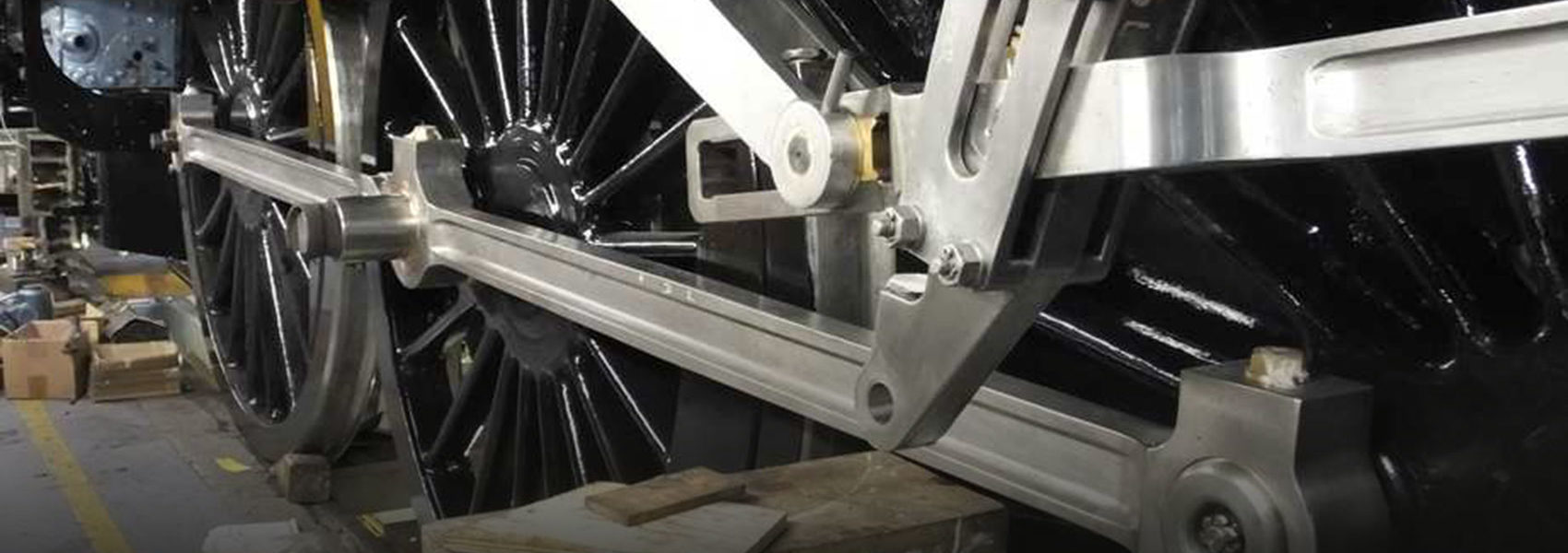
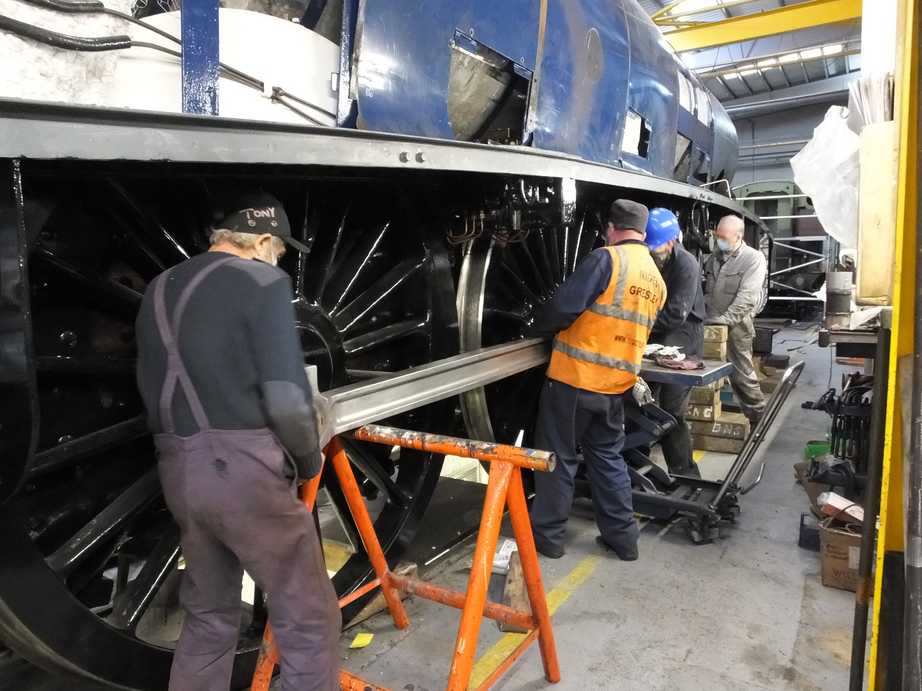
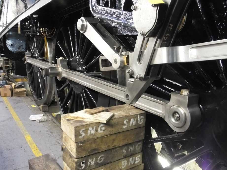
The right side coupling rods have been fitted after assembly with the new knuckle pin. To get the rods on the wheels have to be aligned. This was done by taking the weight off each wheelset in turn and pulling the wheelset round. It was a lot of hard work. The rods were then lifted on to packing ready for the final lift on to the crankpins and the bearing felts were put in. The rods were then finally lifted on. The leading crankpin cap was then fitted.
While the springs were being slacked off the opportunity was taken to fit the new coupled spring hanger 2″ nuts.
Fitting of the right coupling rods also allowed the fitting of the lubricator drive and linkage, all fully refurbished.
The left coupling rods have also now been fitted. The wheels needed a little adjustment to get the crankpins aligned. The leading crankpin cap has been refitted. The speedo crank for the trailing crankpin has had it’s final examination and is ready for fitting.
New dust seals have been fitted to the coupled axleboxes.
Work has recommenced on the little end bearings. All have been machined to length and outside diameter, and rough bored. We spent sometime looking at the differences on BR and LNER drawings before deciding on the tolerancing. The BR arrangement is different form the LNER but the tolerances are well detailed, the LNER tolerancing being absent or vague.
When is the loco expected to be completed.
I saw the loco in the sidings near Rotherham in November 1974 and the driver
Backed up to Holmes Junction and drove slowly towards me and allowed me to take photos. This was at 5.30 in the morning and my newly we’d wife wondered why I’d gone out so early. We lived 50 yards from the sidings. I travelled on the Gresley at Barrow Hill a few years ago. That is why this loco is special to me.
Keep up the good work boys and stay safe.
Keep up the good work everybody the last time I saw this steam locomotive was at the north Yorkshire Moors railway o really enjoyed seeing this locomotive as a child and just seeing it run always made me smile
The loco is looking Brilliant I remember seeing her climbing Hatton Bank in the early 70s whith green arrow on the same day carn’t what to her again.