Weeks commencing 9, 16 and 23 March
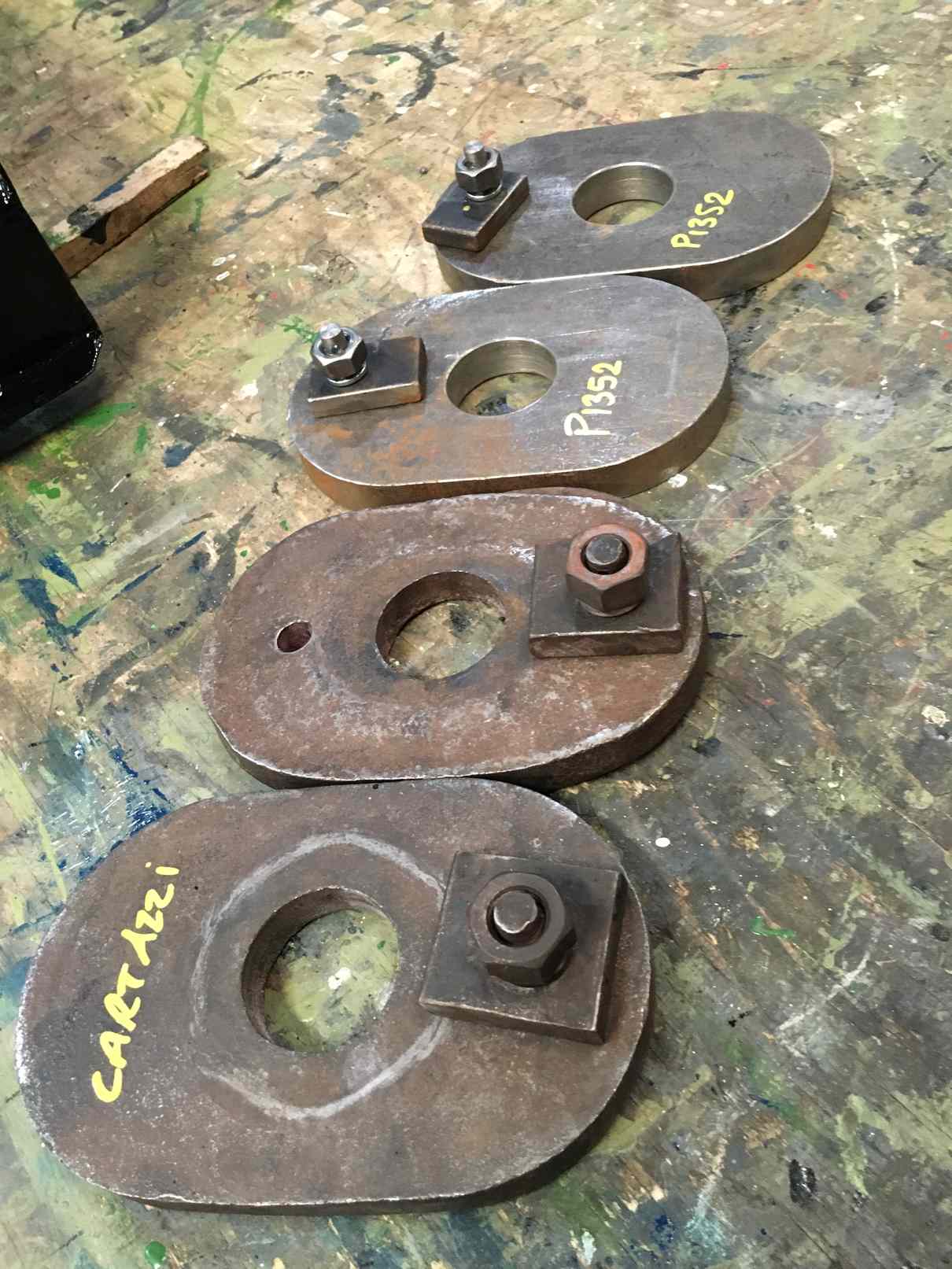
Quotations have been received for the overhaul of the Cartazzi springs and they have now been delivered by one of our Engineering Team volunteers to our chosen contractors. As we were short of two Cartazzi rubber spring bottom plates we have used two of our spares, manufactured when new plates were needed for the tender, as they are identical. They needed studs making for the lock that stops the nut on the bottom of the hanger moving, and this has been done.
We were short of two Cartazzi Spenser boxes as they were loaned to 60009. One was returned and another is still on their loco. The returned example is cracked. I had considered repairing it so to locate the end of the crack and see if repair was feasible it was di-pen examined. It was found to be cracked in a number of locations and was found to be beyond recovery. I have now agreed the loan of a pattern and will get some cast new.
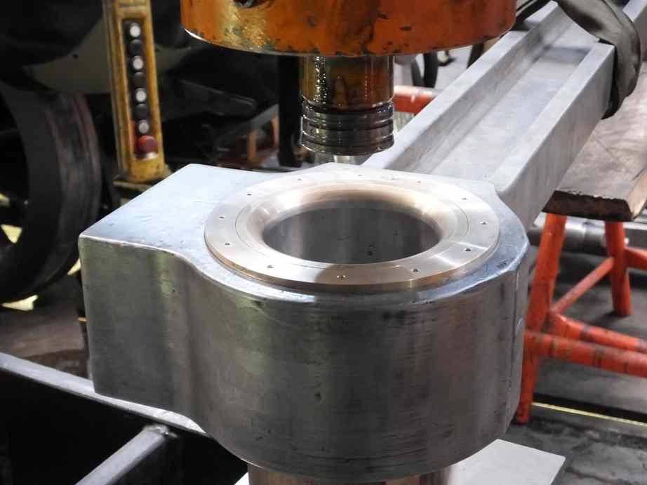
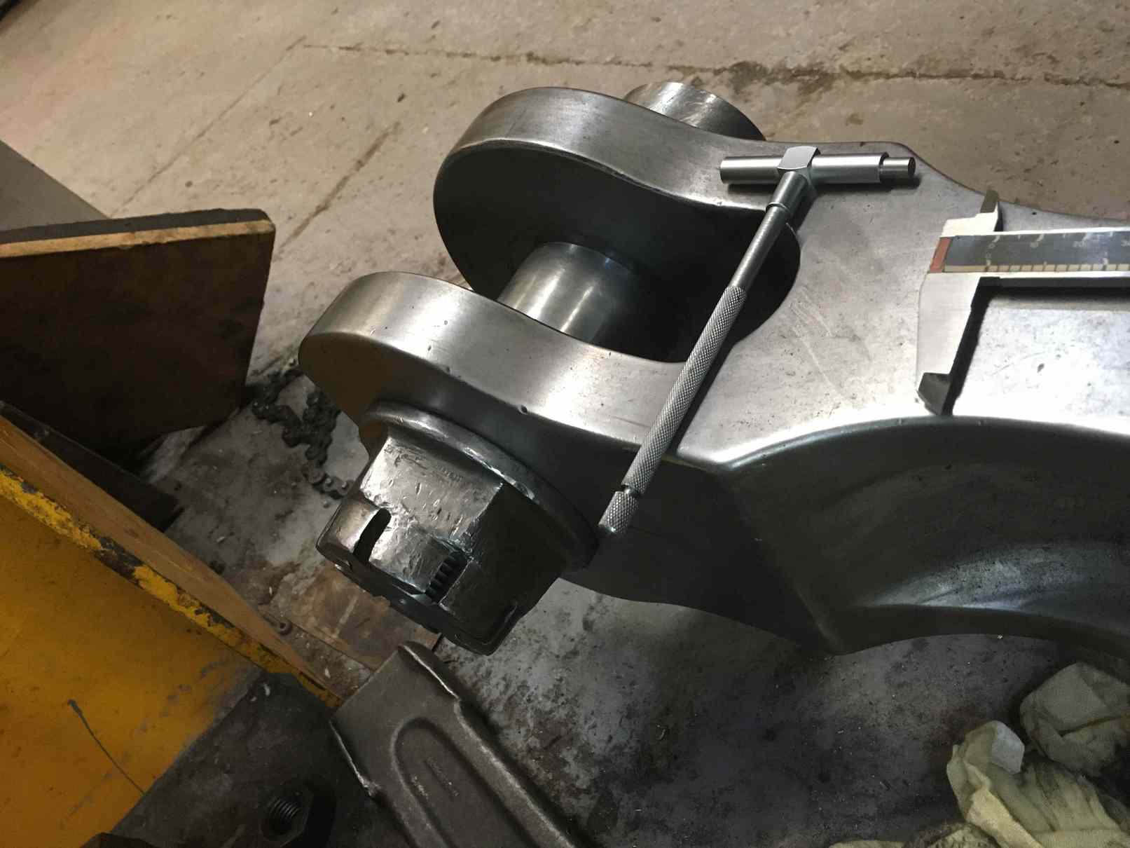
The completed return cranks were also examined around the welded and machined square holes to add them to the register of tested parts.
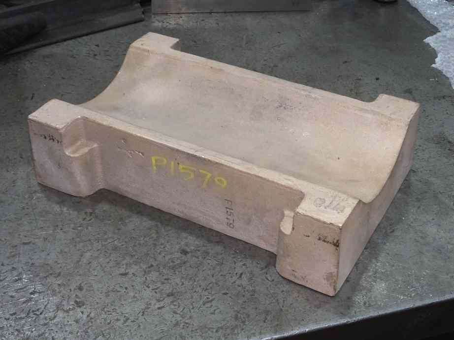
The new Cartazzi brass has now been delivered to a contractor for machining with our drawing. The casting had to be carefully checked to ensure we could get what we wanted out of it. We need a bearing longer that that originally fitted as our journals are worn longer.
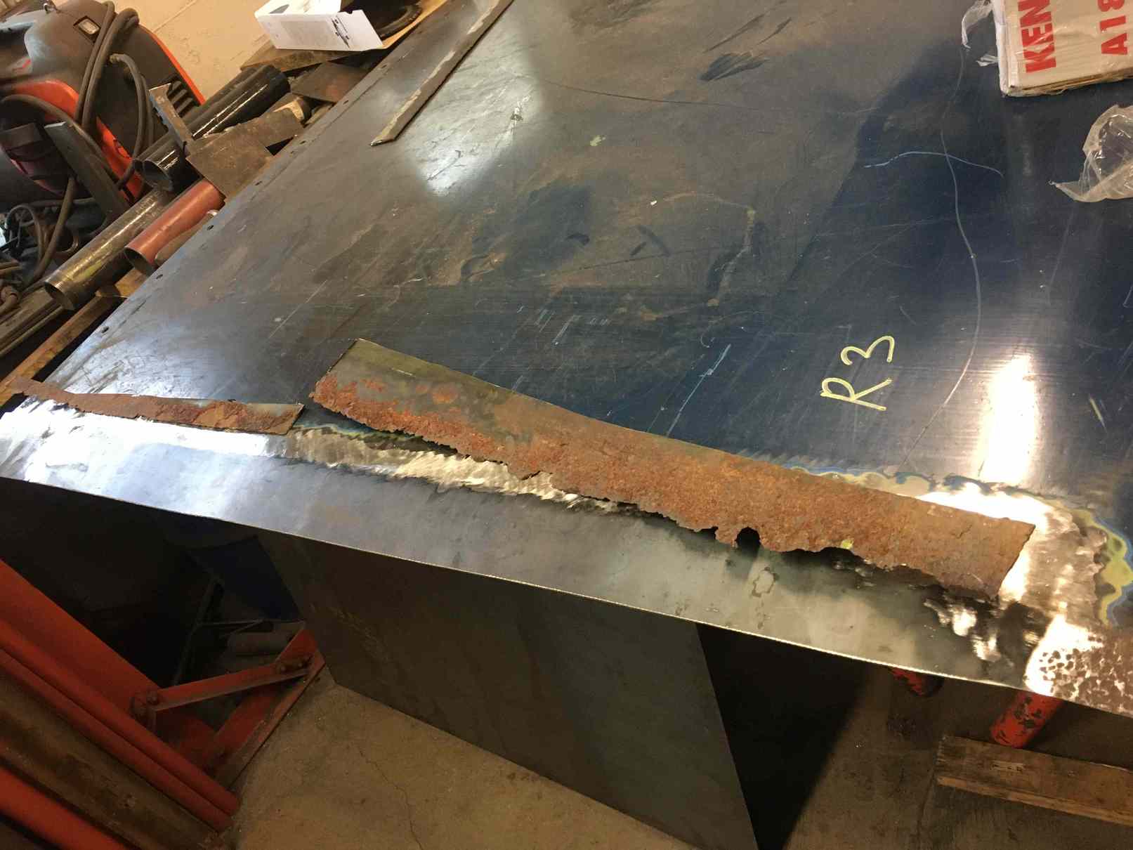
The right-side streamlining on the tender has been trimmed back to align with the piece that goes over the top of the front plate. Under this, along the tender front is a small section of roof. It had corroded through along the edge where it’s fastened to the tender. The little roof is an original fitting with a beaded edge so it was repaired rather than replaced, by welding in a new section of plate. The securing holes were also welded up so that it could be drilled to suit the new top flange on the tender front. It is now in place.
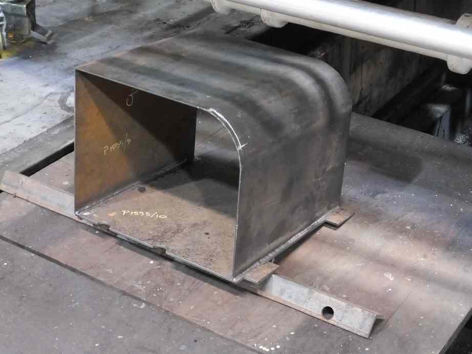
The new tender battery box is taking shape. It is being fabricated by an Engineering Team volunteer and this work is now continuing off site.
The tender coal door frame has been partially riveted in place. Completion was stopped by the shutdown at the NRM. Riveting takes quite a bit of setting up and just about everybody on site gets involved, but it’s good fun.
The tender floor drain pipe after repair has now been refitted.
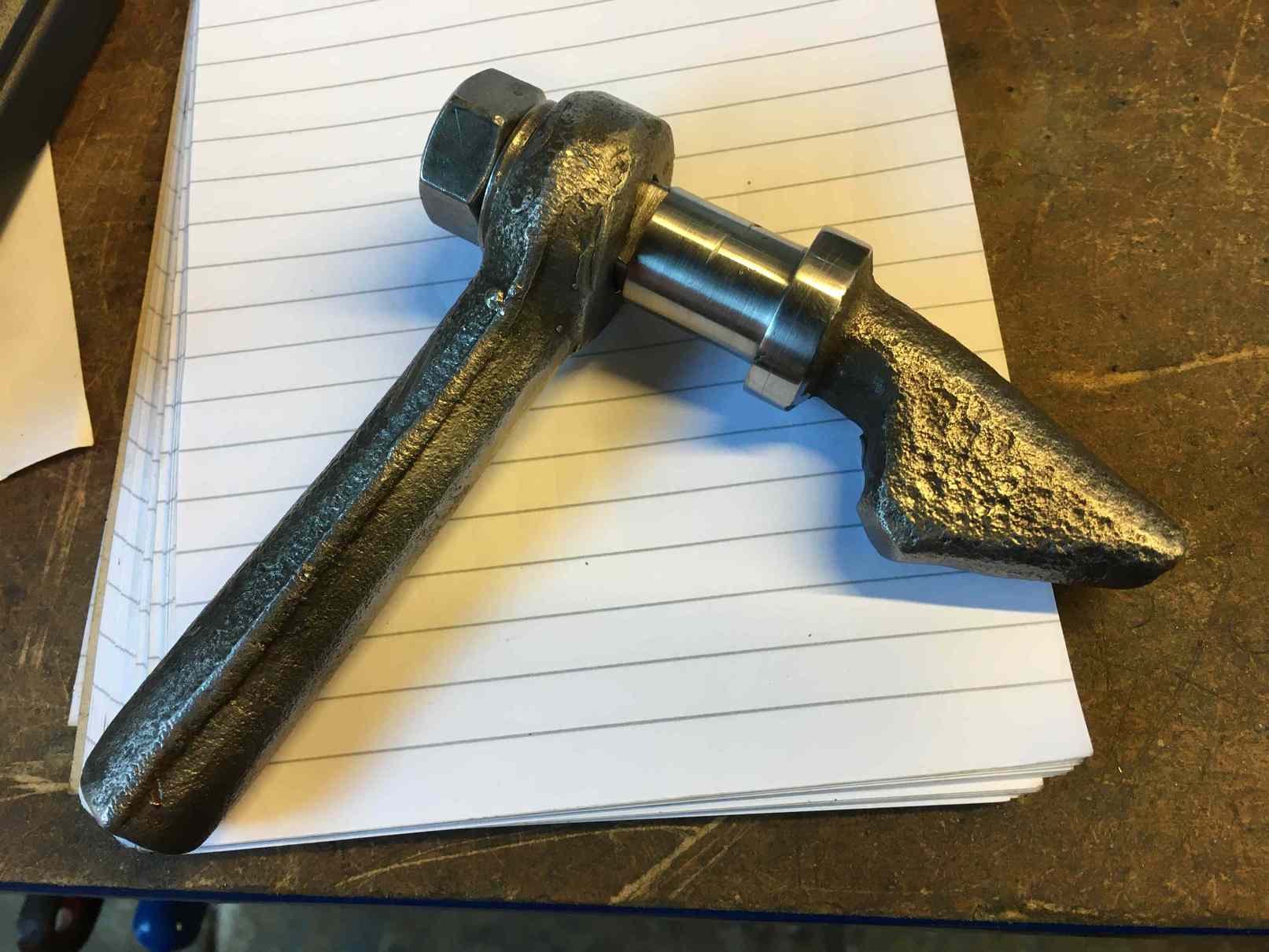
The tender coal door catch was repaired by welding a new spindle on it and it has been machined by one of our juniors in his home workshop under the supervision of his granddad.
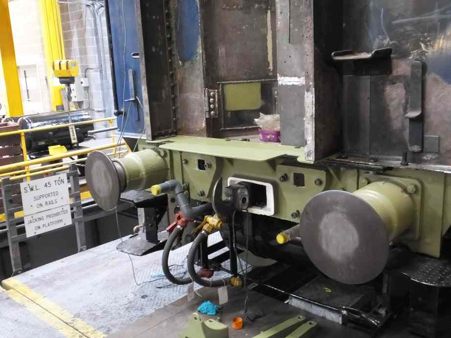
On the back of the tender leading dragbox we are replacing the rather random collection of spacers and plates on the intermediate coupling. The parts give pre-compression to the intermediate coupling spring. New plates have been bought and they will be held up by pins to the dragbox, rather than resting on the coupling. This will reduce wear on the shank of the coupling and enable easier removal of the coupling. The plates have now been drilled through and matching holes drilled in the dragbox.
New bushes have been made for the tender dragbox safety link pin holes. The left side ones have now been fitted.
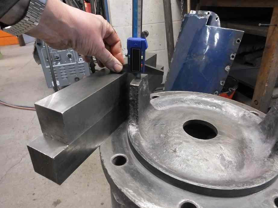
At the back of the tender the lower vestibule support brackets were ready to be fitted until the wedges that adjust the clearance on the support bars were tried in. It was found impossible to get anything like the clearances we need so it was decided to build up the wedges with weld, as had clearly been done in the past. They were then ground near to shape and tried in to see what further work was required.
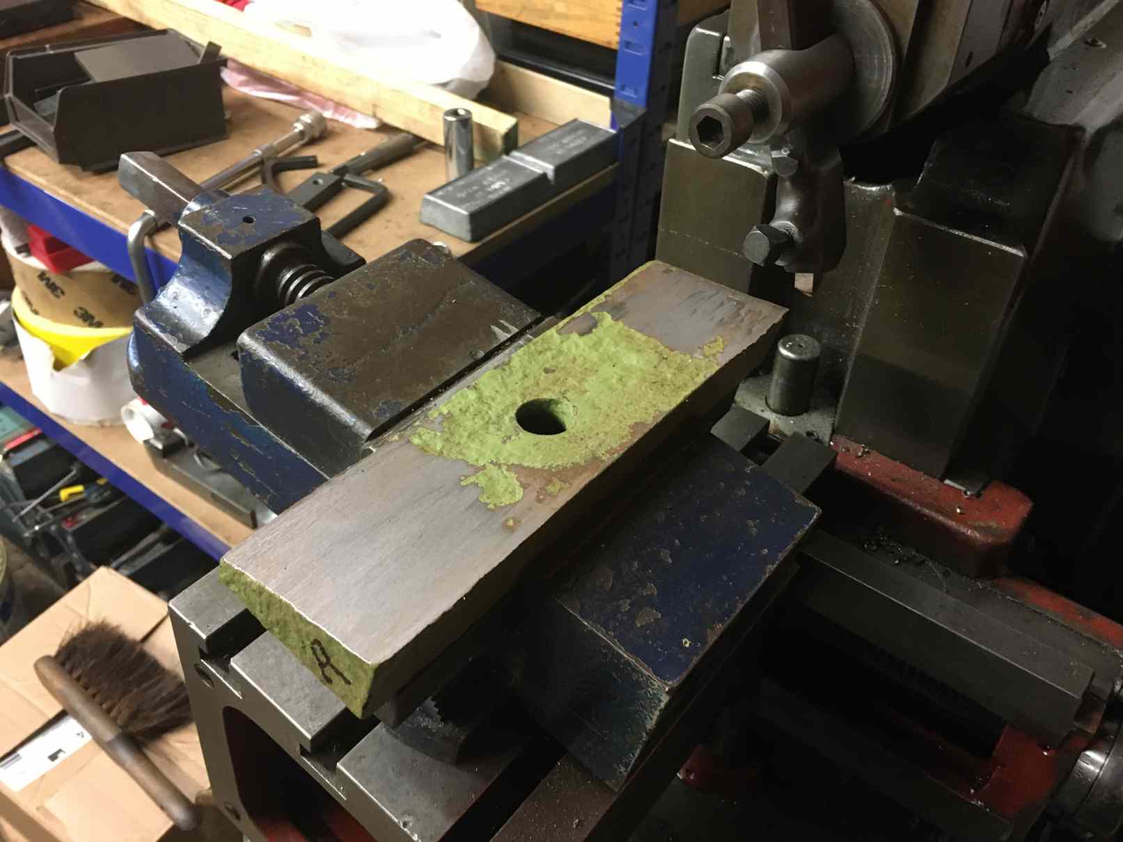
When tried in, measurements were taken and the wedges taken off site for machining. During machining it was found that they had previously been plated over as the plates detached during machining. There are some jobs on the engine that frustratingly seem to open one can of worms after another.
At the top of the gangway the upper support brackets require repair while the upper support spring cover has been repaired and is now painted to gloss top coat and is ready for fitting. The outer Cartazzi frames have also painted and the finish is superb. The inner Cartazzi frames have also been painted to top coat.
Returning to the tender, the new gangway floorplate is now in place.
The piping team has now finished the water filler pipe and the air supply pipe that follows it up to the tender top to the large oil separator. The LH reservoir tank and the smaller tank near it are now in place with the drain pipe from the larger tank. This pipe has been changed to heavy duty steel pipe from copper. Though harder to work with it will be harder wearing in traffic, the old copper pipe showing much damage when removed.
The large injector pipe flanges have now all been refaced. These were found to be very worn, to the point where you wonder how they got to the shape they did. The faces have all been filed flat, checking them against a flat surface.
The new blowdown valve has been temporarily fitted to the firebox throat plate and the routing of the blowdown linkage, exhaust pipe and the steam supply pipe to the air pump is being planned.
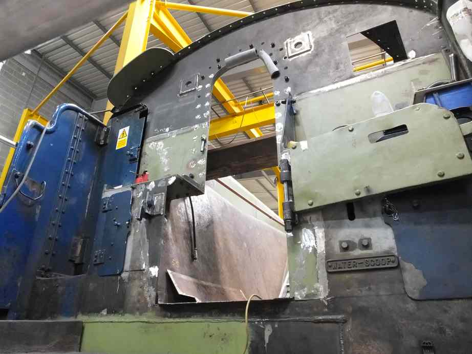
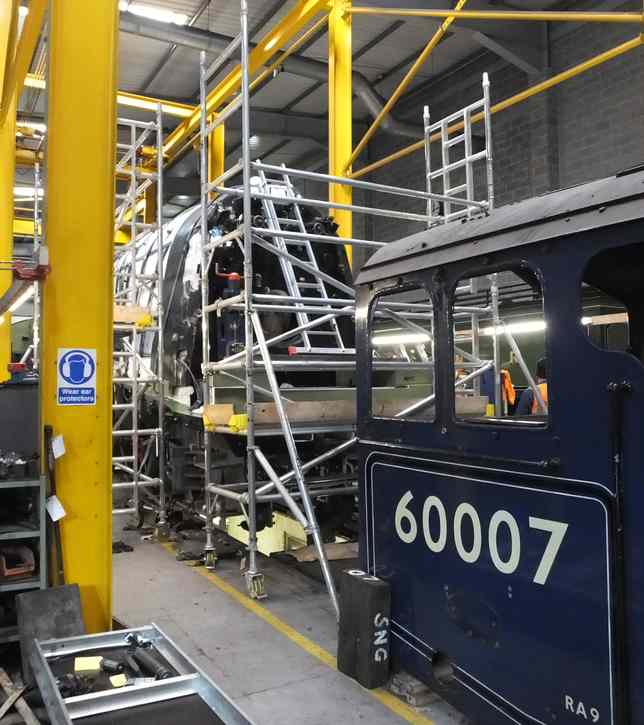
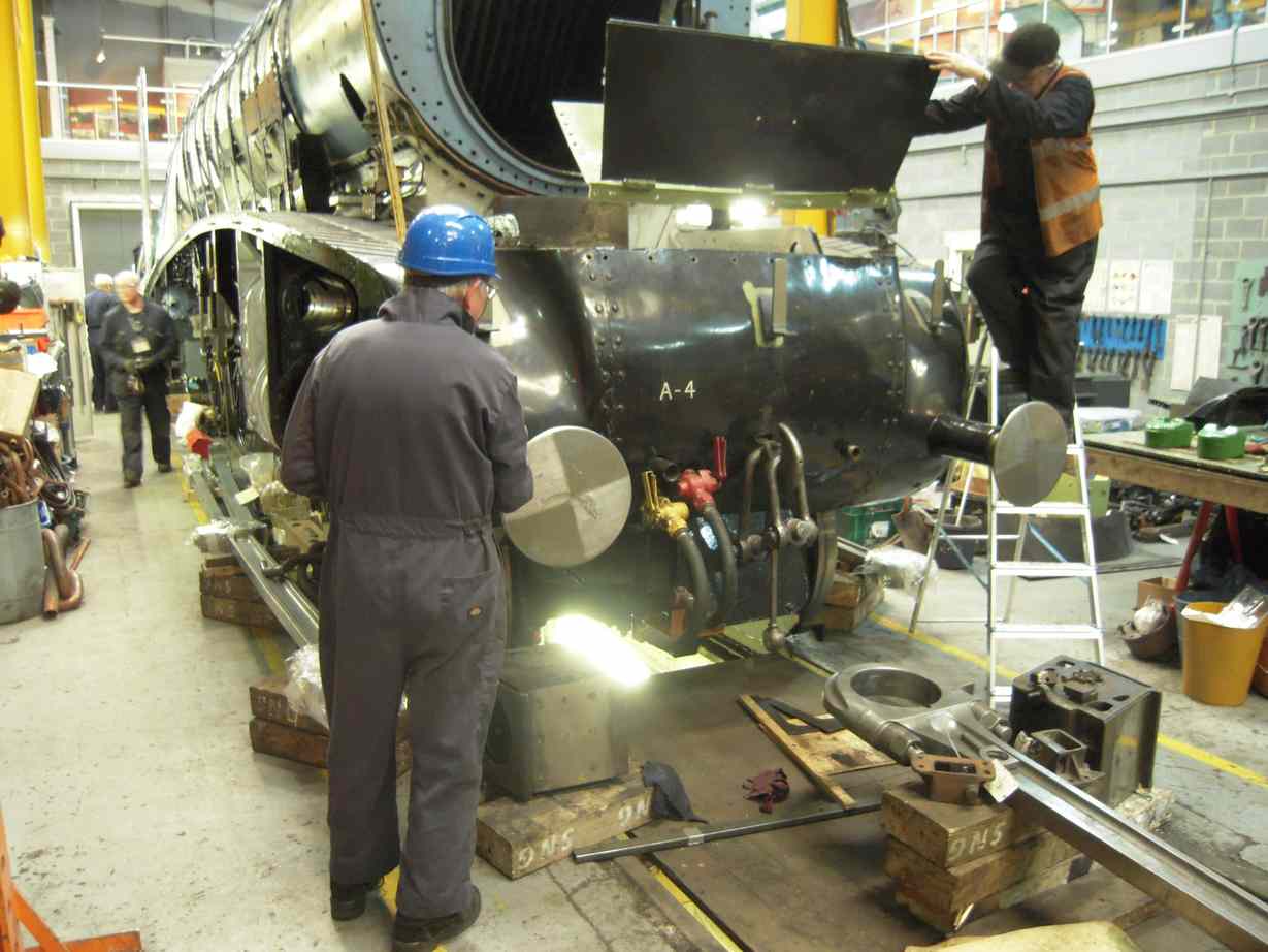
Further progress has been made with the boiler cladding by a couple of Engineering Team volunteers, who have done a great job sticking with this. The firebox backhead corners have been put up and the large triangular piece that goes across the top of the firebox and lines up with the cab front. We have 60009 on site so we’ve looked at their cab cladding and it is much more complete than ours. Where theirs is almost fully boxed in we do have various gaps and cutouts where the insulation can be seen. We are considering if we should cover these areas.
The cladding sections immediately in front of the backhead corners, down the sides of the firebox, were corroded to nothing along their lower edges. These were cut off and new sections welded in.
Work has also progressed on the streamlined casing towards the front right of the boiler. This has required extensive weld repair and are now being tried in place. It has taken quite a bit of fitting and tweaking and I’m still to decide if this method of repair is worth pursuing. It might be time to renew larger sections.
With the new valve guide reamed through a start has been made on the machining of the securing fitted bolts. This job will now continue off site.
The steam chest valve covers have now been trail fitted and their fit against the valve liners checked. The projections that provide an additional stop to the movement of the liners have been rebuilt with weld and finished to size.
During the measurement of the valve guide assemblies one of the bolt seat faces on one of the covers was found to be damaged and meant that the nut on the securing bolt would contact on an edge and not sit flat. This face was rebuilt with weld and is now off site to be machined by a contractor, as none of us at home have a machine big enough.
The distances between the exhaust ports have been measured and these dimensions will be used to set the spacing between the piston valve heads.
All the gudgeon pins have now been fitted after returning from having their journal surfaces ground. The last one, RH, being fitted into its crosshead with a new key.
The lower cod’s mouth door is hinged to a section of footplate which was riveted in the last report. It has now been painted and fitted in place.
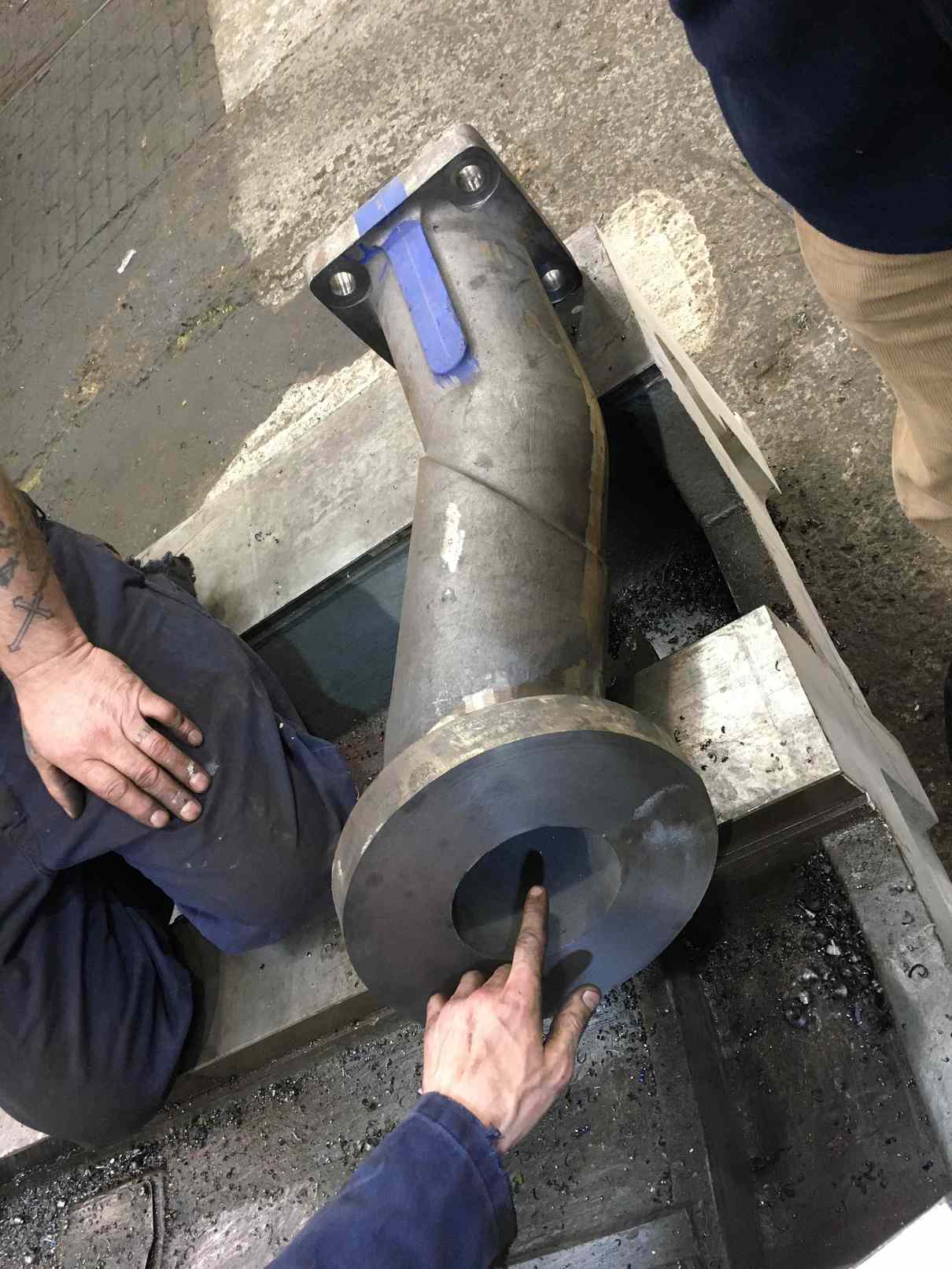
In the smokebox corroded studs are being removed in preparation for the fitting of the cast iron steam pipes and chimney casting. New studs have now been fitted to the leading chimney flange. Two of the three cast iron steam pipes machined at contractors are finished.
The reverser reach rod has now been installed. It is in two halves and joined by fitted bolts. The old bolts were a good fit so have been reused. It is secured by new hardened and fitted pins at either end to the reverser stand crank and the weigh shaft lifting arm. The nuts on the end of the weigh shaft have been fitted and reamed for taper pins. The lifting arms are pinned to the radius rod die blocks and these have been fitted. After installation the reverser handle was turned and all works very smoothly.
The direction of the loco for the OTMR recording system is detected by an electrical switch contacting a plate of the back of the reverser reach rod. The bracket that mounts the switch was cleaned up and tapped and the switch fitted. Its operation has also been checked.
The GSMR radio aerial has been tried in place, on the tender top where new plate has been installed. A new foam sealing gasket for the base has been made.
Off site, the ex-service AWS bell which was found to be functioning but had internal damage. This has now been repaired using recovered parts and a spare unit has also been refurbished.
The leading coupling rod bearing oiling rings have now been fitted after being machined by an Engineering Team volunteer. They pressed on very well and lined up very well with the faces of the bearings. Not an easy thing to achieve when the recesses they fit in to are conical and worn from original dimensions.

The knuckle pins have now been lapped in to the trailing coupling rods and the fit is very good. This has not been an easy job. The pins have to be a good fit in two conical holes and the cones do not geometrically coincide. The pins now require some final machining before hardening of the journal surfaces. This work is continuing off site.
Work continues on the renewal of the loco brake bushes and pins with the bushes now completed.
The steam heat valves have been rebuilt with a number of new components as sorting one fault has lead to finding another on this job. They are now ready for testing, again.
This is the 49th update—you can read all the previous instalments here.