Weeks commencing 17 and 24 February and 2 March
It was hoped that the steam heat valve spindle mentioned in the last report was recoverable but upon closer inspection it was found to be cracked so a new spindle has now been made. The new valve has seen a little lapping in but there’s more to do.
The boiler and ashpan position has changed a little from when last fitted. This has had the knock-on effect that the ashpan sprinkler bulkhead fittings have moved and the right-hand one is now too close to the frames to get a nut on. The ashpan has now been modified to allow the fitting to move, however a new way of securing the fittings will now have to be found.
The belly cladding bands were lifted inside the crinoline and secured in place with new screws. Meanwhile the outer straps were being painted. Fitting the inner straps allowed the belly cladding sheets to be fitted. A very awkward job. Most of the existing sheeting, though looking a bit rough, is serviceable and is hidden from view, so this was refitted.
We hit a problem with getting the sheets under the crinoline. There seemed no way of getting them in as they are bigger than the pitch of the crinoline uprights and it was impossible to get them in under the loco. So one of the uprights was cut and this gave us a window where the sheets could be put through then slid along the sides of the boiler. When all the sheets were in, the upright was welded back together. The upright was cut along an existing weld so perhaps this method had been used before.
When the belly sheets were in they were pop-riveted along the bottom seam and the outer bands secured to the crinolines at the top and pulled together with long threaded studs on the bottom. The cladding around the throat plate presents quite a challenge because of the shape of the boiler and the difficult access due to the location of the air pump. Further work is required here. It was found that the securing of the cladding would be aided by the addition of a further band not originally fitted here. So new material was obtained and a new belly band fabricated and fitted. This has all been a long tough job carried out by our volunteers.
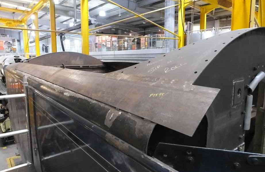
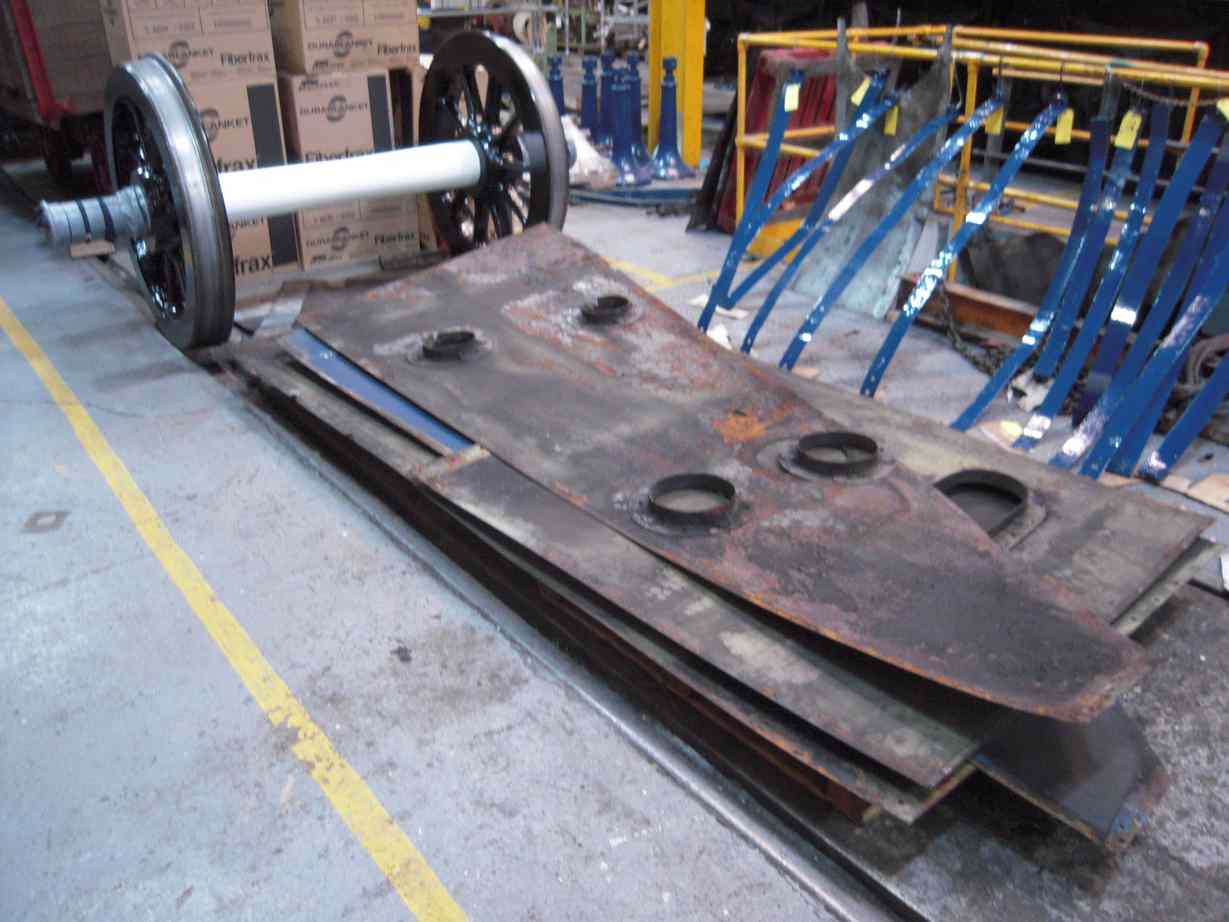
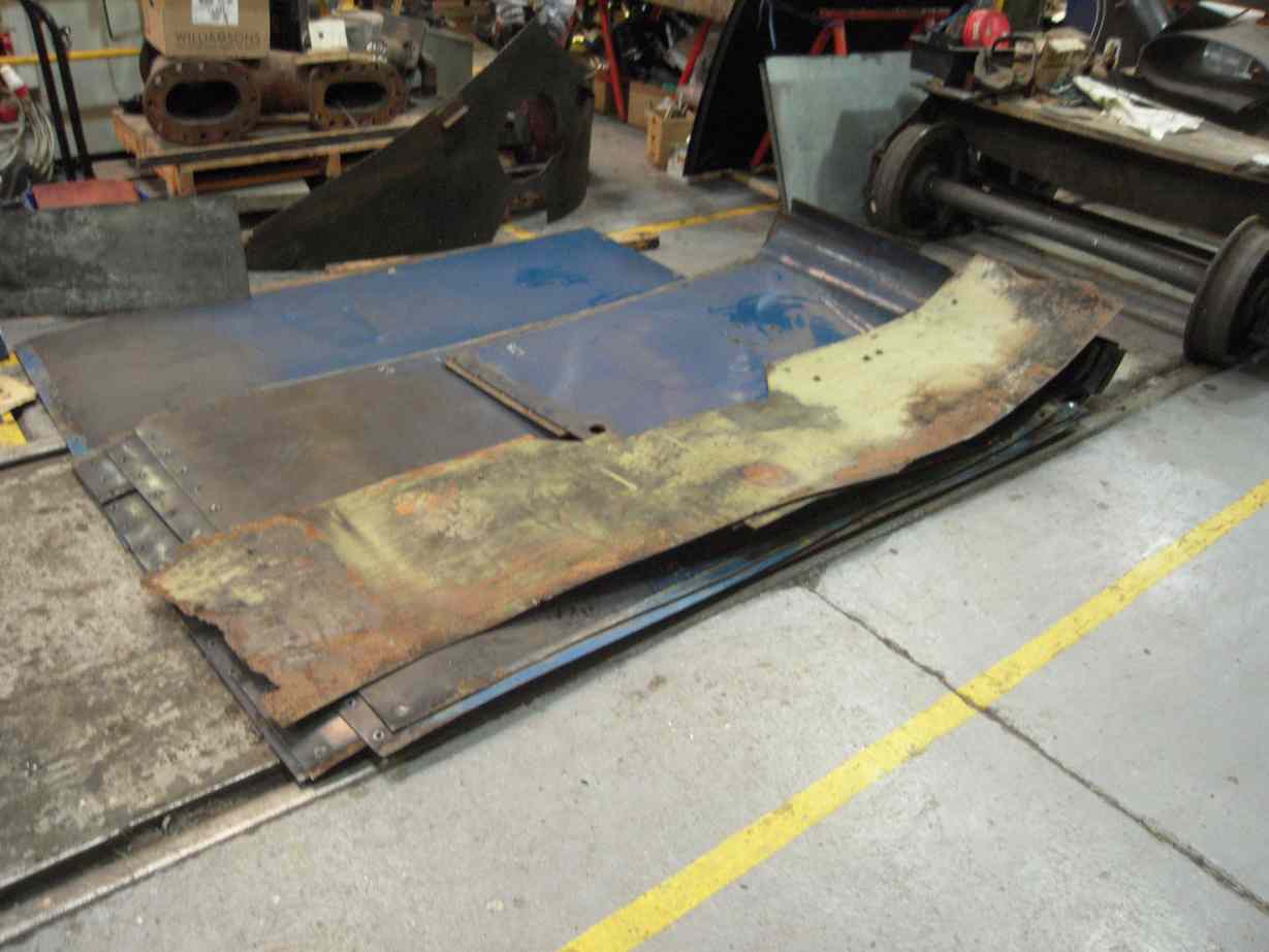
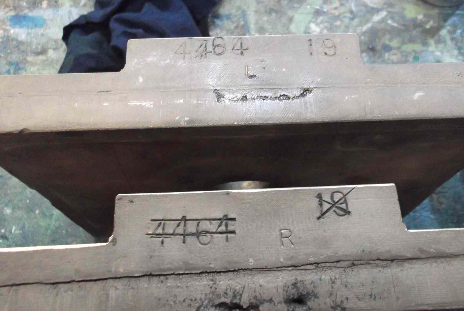
Meanwhile work has progressed on the main cladding panels. They have all been cleaned and given a coat of primer. The panels were assessed for condition and sections marked up that are wasted and require cutting out and replacement. New steel has been obtained, as a flat sheet and a piece rolled to the radius of the lower roll in the cladding where it meets the footplate. To explore the practicality of repairing the panels, one was repaired with a new flat section where it had wasted to lace along it’s edge where under a cladding band, and along the edge where on the footplate. Putting in sections will change the stiffness in that area and it is to be seen if the panel will roll correctly when fitted to the loco.
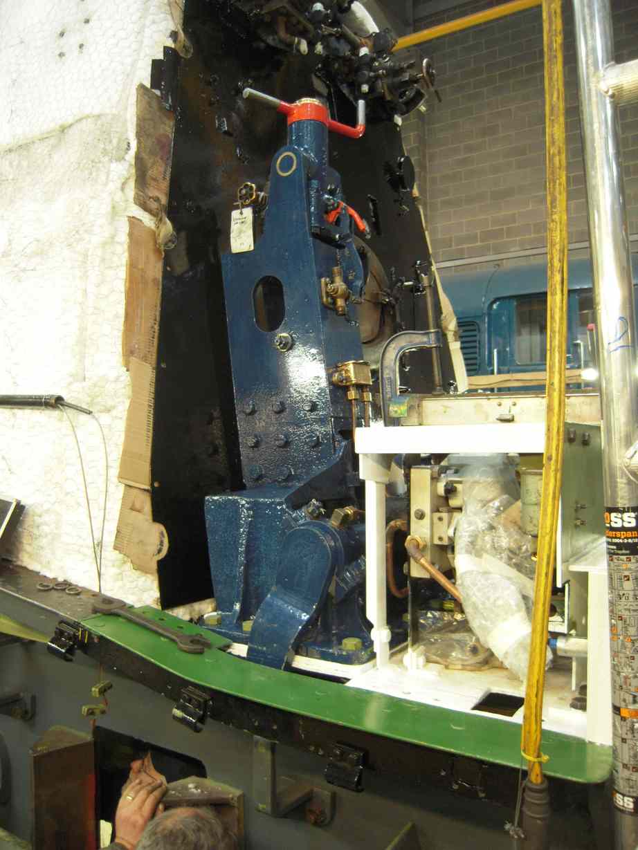
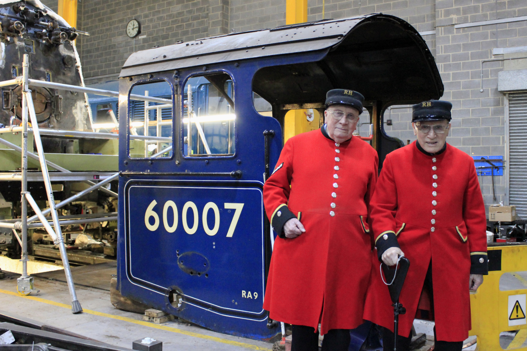
The backhead cladding was rubbed down and painted. Various openings in the back head valves were covered to keep contaminants out. The backhead has now been painted to top coat. Completing the painting allowed the reverser to be refitted.
The dressing of the coupling rod bush keyways has been completed which has allowed the pressing in of the crankpin bearings. All bearings pressed in satisfactorily. When the bearings were pressed the close up on the bore of the bearings was measured and the side projection was measured to compare to our drawings. The leading oiling rings are now being made to the dimensions of the bushes to give a flush face across the crankpin wheel face.
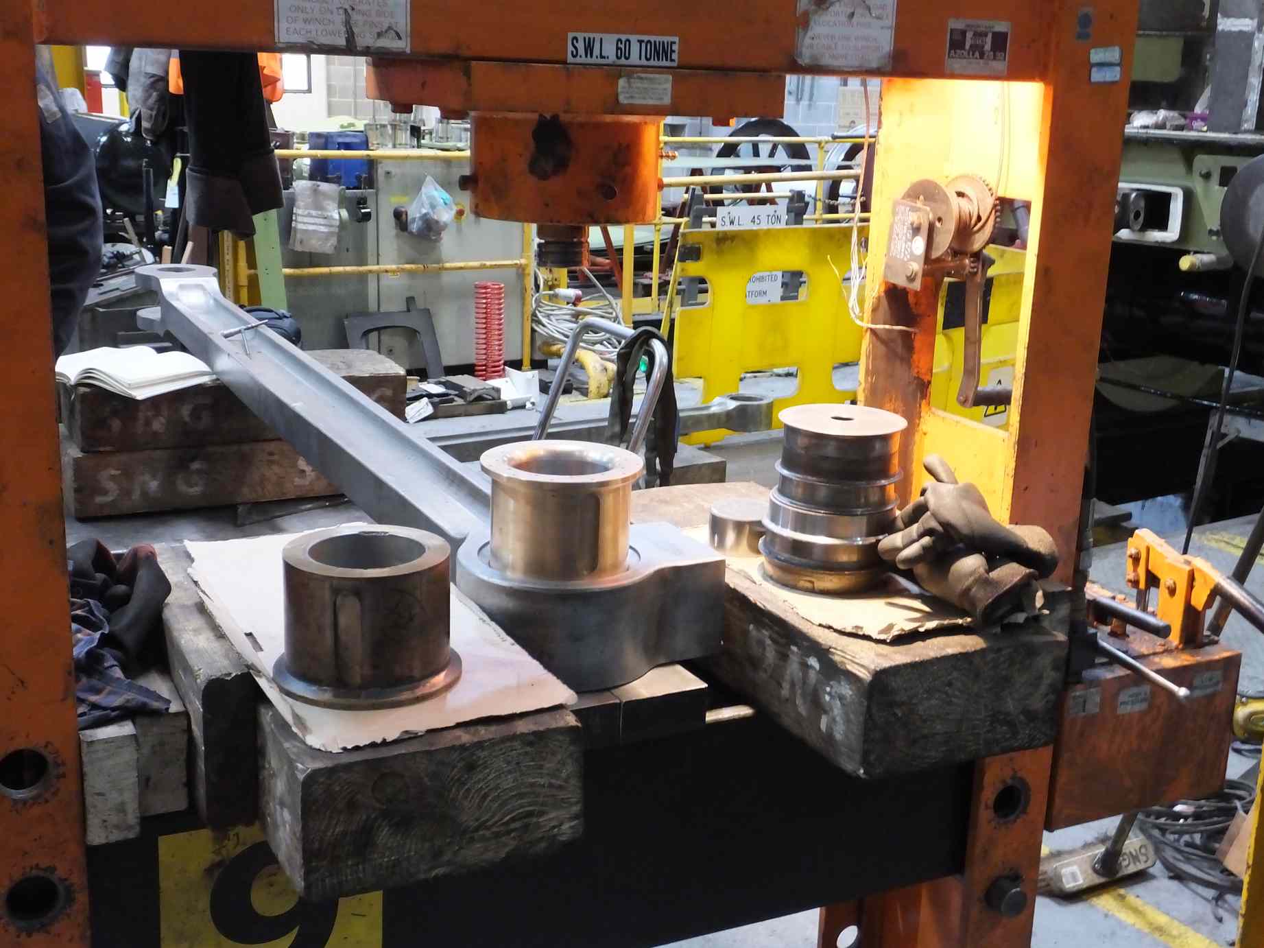
Before the fitting of the bearings all the oiler felt pads were put in to soak in oil, and all of the oil reservoirs in the rods cleaned out. After fitting the bearings were wrapped in a thick cling film.
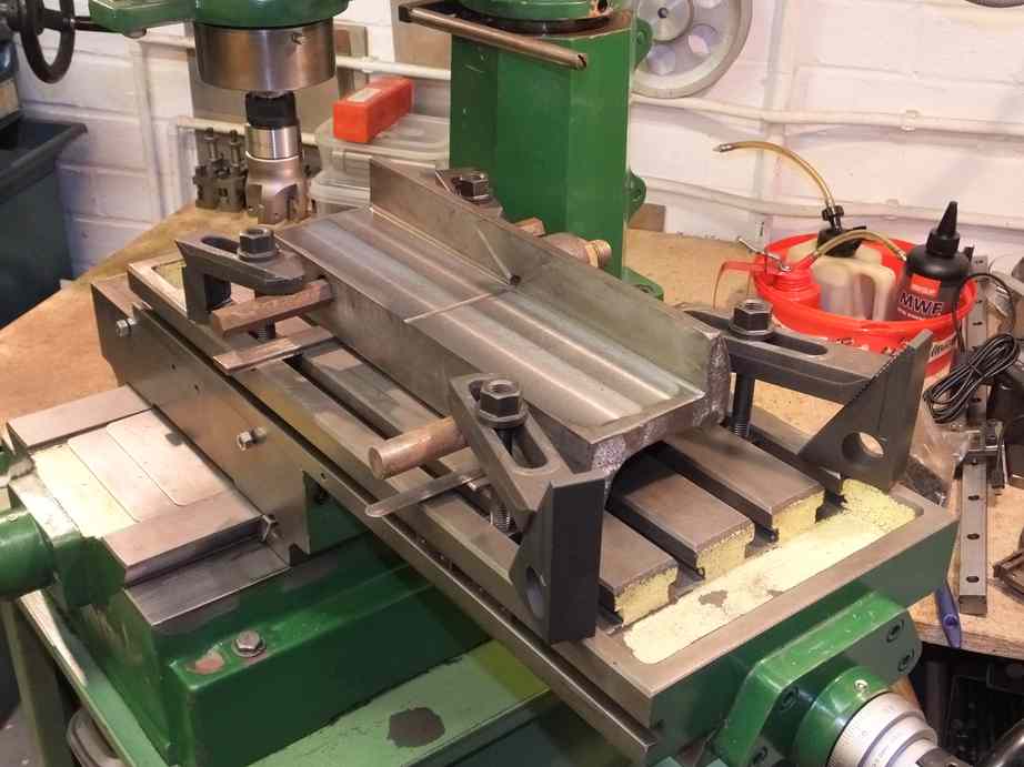
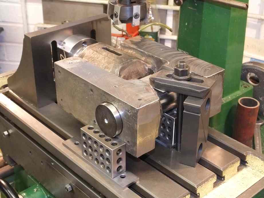
Work progresses on the knuckle pins with lapping the right hand pin in to the rod. As this pin was quite a way under the outer surface of the rod it has had to be re-machined to reduce the taper diameters so that the full hole in the rod will be lapped.
The new valve guide has now been fitted to the valve chest cover. Some difficulty was experienced doing this as the holes through the cover were not square to the surface so when reaming through, the reamer was wanting to change direction when it passed from the guide in to the cover. Eventually the job was done and new fitted bolts are now being made.
The other valve guides and covers have been inspected. They’ve all seen plenty of duty but most will soldier on for a while yet, however one one was unacceptably worn out of position. This was recoverable and was machined to improve its alignment. Now that we have the dimensions of the valve guides we can move on to getting the crossheads whitemetalled and machined to size. The leading crossheads also require re-bushing and this is progressing.
The valve chest covers have lugs that contact the end of the valve liners. This is to prevent the liners from moving if the interference fit of the liners is overcome. To ensure contact the covers are tried in place and if there is a gap the end of the lug is built up with weld and filed to give the correct length of lug. This is now being done.
The Cartazzi springs loaned to 60103 have been returned to York along with some of the components loaned when 60009 failed with a broken Cartazzi hanger. The ex-service Cartazzi springs and the returned springs were cleaned off by our Junior Volunteers, and quotes are now being sought for their refurbishment.
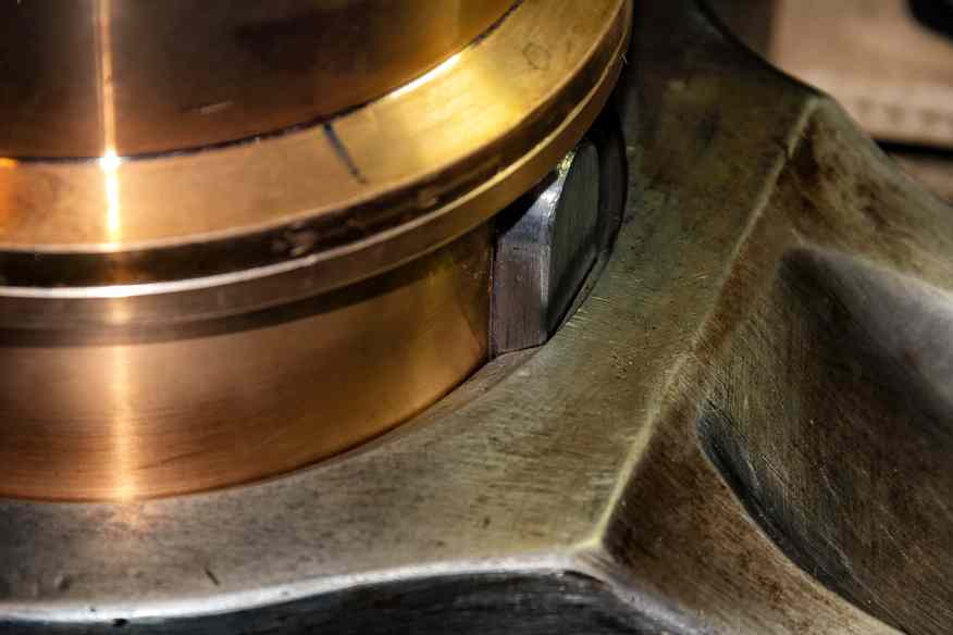
The steel Cartazzi wedges were put up on the marking out table for assessment. The recently machined bronze wedges were tried on and the right side assembly sits well enough for reassembly, but the left will require machining of the steel side. This is now with a contractor for machining, as all our capable volunteers are on other tasks. Both of the steel wedge sections should be manganese steel lined but like the trailing loco horns, they are lined with mild steel and shows considerable wear.
New Cartazzi Spenser springs have been assembled.
The new steel for the tender battery box has now been received and the main box shell has now been fabricated.
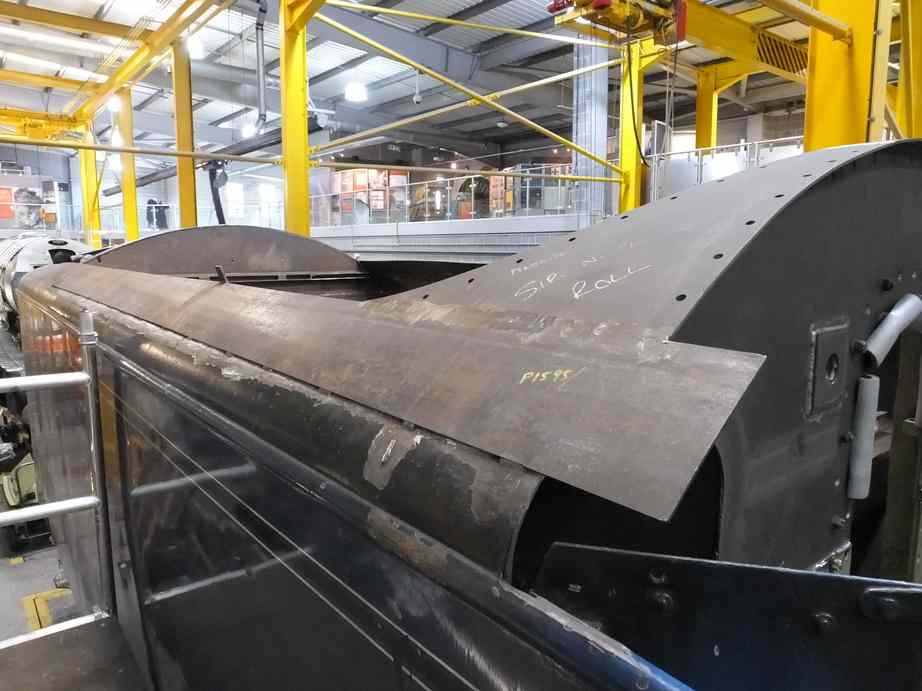
Meanwhile the Boilermaking Team has been working on the fitting of the new material to make up the streamlining along the right side of the tender and over the front bulkhead. The new steel arriving with the battery box flat pack.
The front tender weight has now been secured with new bolting.
The safety link holes in the tender leading dragbox have been cleaned out. Some of the holes were bushed and they have now been cut out. The other bushes came out with the pins during the stripping of the tender. New bushes will now be made.
Work continues on the manufacture and fitting of the new bushes for the loco brake gear.
The main injector pipework has been annealed and Pipe Fitting Team has been working round the air ministry joint cones to check their fit in the pipe ends. The existing pipe cones are also being examined for fit, and so far so good. The next step is to look at the fit in to the new clackboxes.
The bronze injector pipes that end in flanges that go against the injectors were examined and have been found to be very worn. They are now being repaired to get them back to flat.
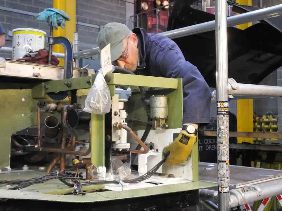
Elsewhere most of the Pipe Fitting Team’s efforts have been directed at the installation of the new pipe runs on the top of the tender. The right hand water filler flange has had to be moved to the rear to allow the large air supply pipe to come up the same drain duct as the water filler pipe. The air supply pipe comes from the air pump to the reservoir tanks on the tender top. To make the arrangement as compact as possible, flanges were altered from standard and welded on to the pipework, removing the need for additional fittings. The air tanks have also trial fitted to ensure no pipe run clashes.
Also up on the tender top the water filler lid hinge and catch have been bushed and fitted with new pins. A patched wasted section of the lid was also cut out and new steel let in.
This is the 48th update—you can read all the previous instalments here.