Weeks commencing 4, 11 and 18 November
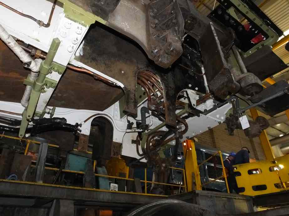
With the boiler in place the Pipe Fitting team have been reinstalling the cab floor structure and pipework. A new conduit has been fitted across the floor to protect the OTMR cabling. The OTMR sensors have now been calibrated and the results are being examined. A couple are outside of manufacturers spec, but may be within what is required by the OTMR system. This is being investigated.
At the smokebox sides the atomiser brackets have been rebuilt. An improved arrangement has been fitted to add rigidity, and also the oversize nuts used as spacers have been replaced with machined spacers.
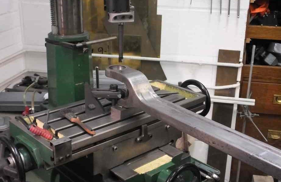
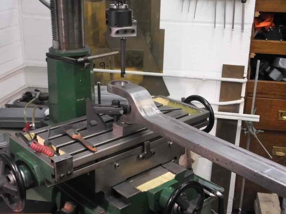
Meanwhile, two of the valve crossheads have been welded up where the taper pin holes are oversized and threaten to break through. These will now require machining to size, redrilling and re-metalling. The new valve crosshead guide castings are now with contractors for machining.
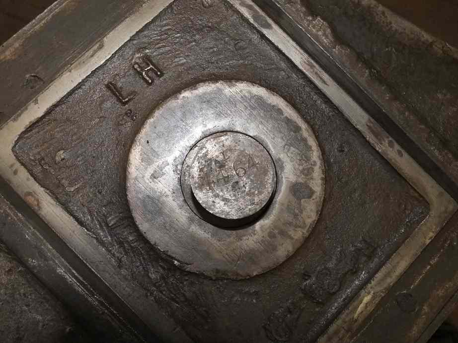
The boiler washout plugs and doors have been stamped up with new identifying letters and numbers so these have now been noted on our drawing for future reference. Where the boiler has come to rest on the frames it is hard up on one of the crinoline brackets at the firebox end so it was cut off and will be welded back on when we fit the crinoline.
The boiler is held down at the rear by the diaphragm plate. All new bolting has now been fitted between the plate and the loco frame stretcher and the foundation ring. With this bolting in place the cab floor piping and the ashpan spray pipes can be fitted. At the smokebox end all the bolts around the saddle are in and any excess length ground off on the smokebox side.
Under the foundation ring sides are retaining/expansion brackets that hook under brackets on the loco frames. The brackets foul new material put in the ashpan, so this was cut out on the left side and the bracket fitted. The right side required a shim plate to space the bracket correctly but a little more work is required.
The ashpan is held up on pegs and studs in the boiler foundation ring. The pegs have now been fitted and also the rocking grate shaft brackets that are fastened to the foundation ring. These brackets also hold the ashpan against the foundation ring. Cotters go through the pegs to secure the ashpan and these are now being fitted.
The last of the tender tank bolts have now been fitted, the rear corners requiring shim plates put in between the tank and frame brackets. Progress is being made on the tender front with the fitting the large upper front plate. It required some effort to get it in the correct location as in places it has to align with, and is between existing brackets and plate. The holes in the tender structure have now been marked through and the plate is being drilled. The removable shovel plate has been stripped and examined and shows a lot of wastage. It is a relatively straight forward fabrication so should be easy to replace.
The return cranks have now been fitted to the crankpin squares. Some work was required to the squares, just as the radii on the crankpins had to be finished at York. The machining marks left on the squares required removal as the multiple passes of the tool during manufacture had left steps, which we had to patiently remove to ensure a good fit for the cranks. The left crankpin securing bolt is now being fitted, which requires the half hole put in to the corner of the crankpin square.
The last slidebar bolts and nuts have been completed. All bolts now drilled for split pinning. We only await the completion of the left crosshead repair and all crossheads and slidebars will be finish assembled.
All the gudgeon pins have now been lapped in and they fit very well. The LH crossshead has a worn keyway, looking as if a gudgeon pin may have been moving in the past. New key material has now been purchased and will be fitted. The keyway has been repaired by careful filing using slip gauges to ensure straightness and parallelism. The new bushes for the crosshead for the union link pin are now made and fitted.
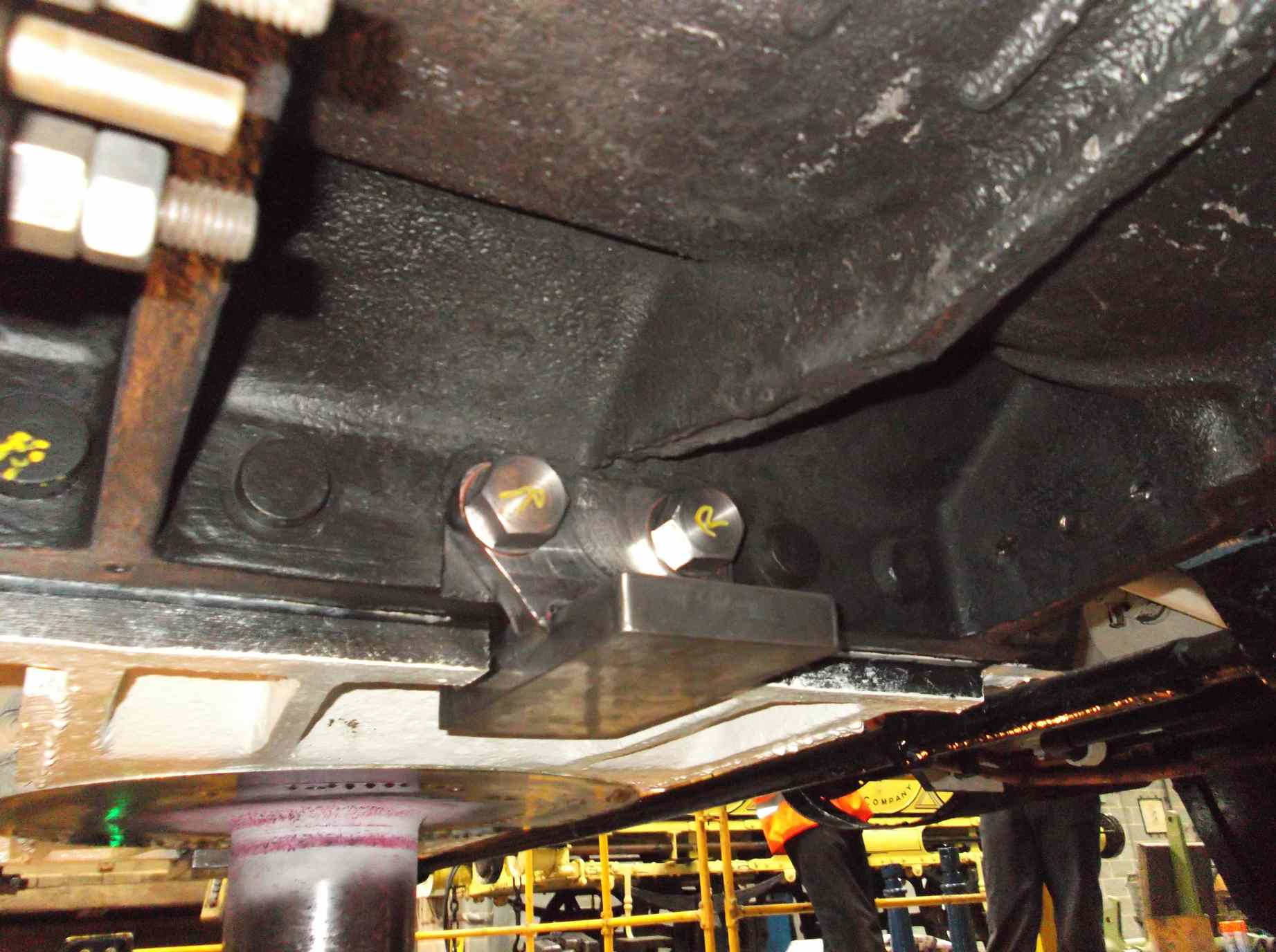
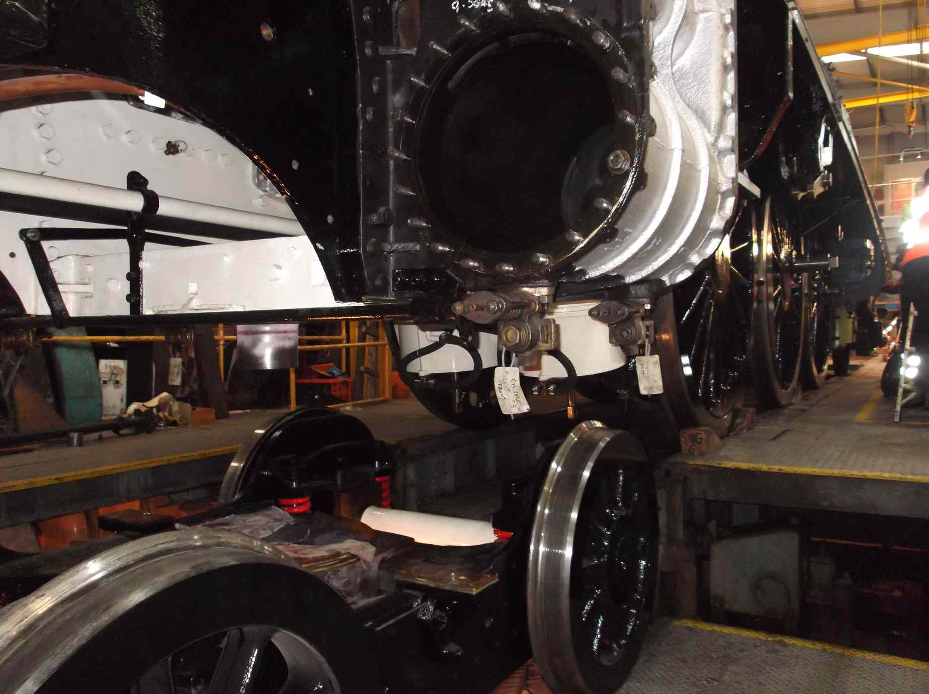
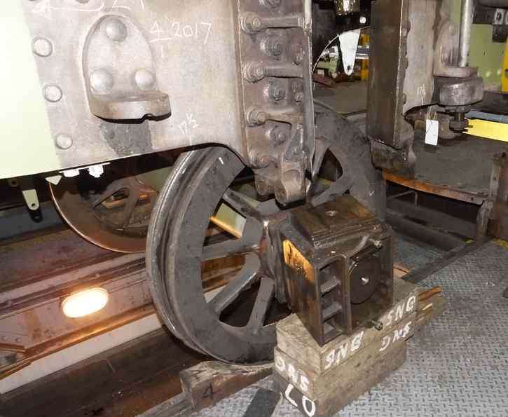
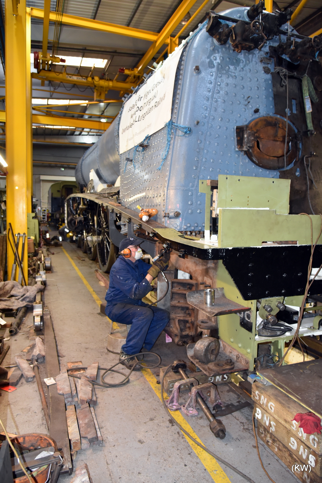
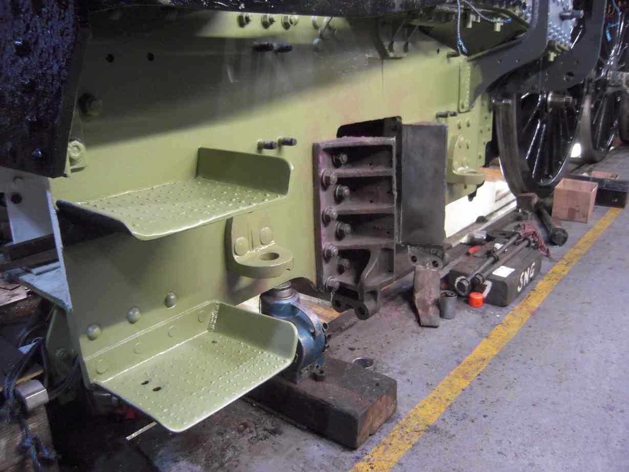
After fitting the boiler the loco was returned to its usual position in the workshop. After securing the boiler the loco was then moved on to the wheeldrop to lower the bogie. With the loco on all its wheels it moves quite easily. When on the wheeldrop the bogie was lowered a few feet for fitting of the side-bearers to the loco frames. The new fitted bolts to hold the side-bearers were machined by one of our volunteers and they went in with a satisfying drive fit, with the side-bearers held tight against the frames.
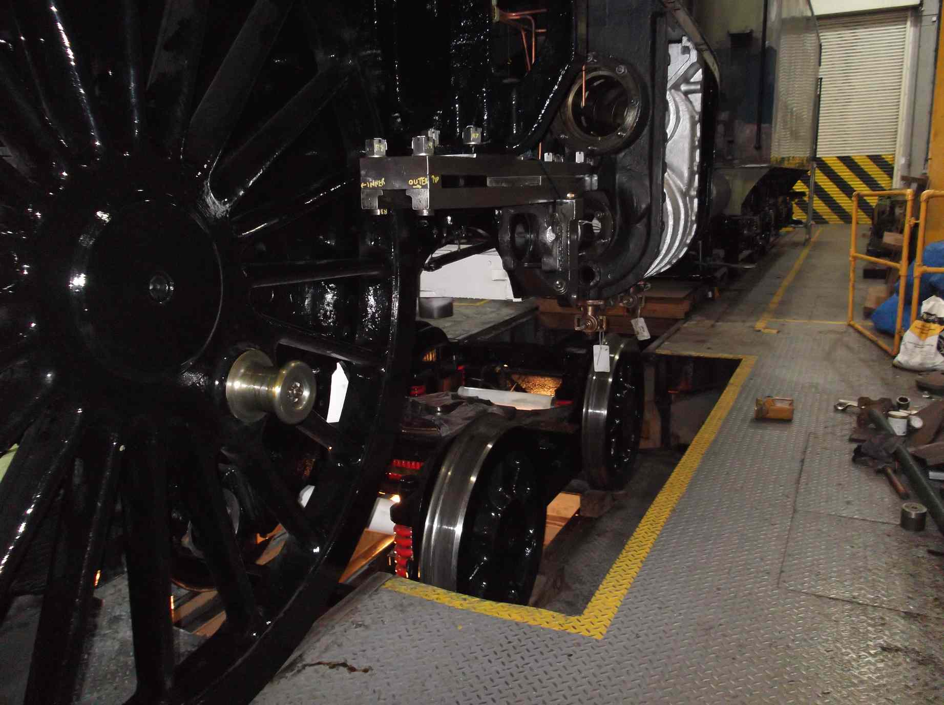
While on the wheeldrop the loco centre bogie pivot spigot was di-pen inspected to complete our photo record of the inspection of the loco bogie stretcher. The bogie was then raised back under the loco and the side-bearer gaps either side are satisfactory and even. With the bogie back in place the bogie pivot bolt was fitted and the nut fitted and pinned.
The leading steam heat valve after failing pressure testing has been lapped in again using our new diamond paste. The same is now being done to the tender valve.
The loco adjustable brake pulls have now been fitted with new bushes and pins. All pins are also now drilled through for their split cotter pins. The short end holes are not bushed but did show some distortion so were bored out true. Half of the six loco brake hangers have now been machined where rebuilt with weld to remove wear.
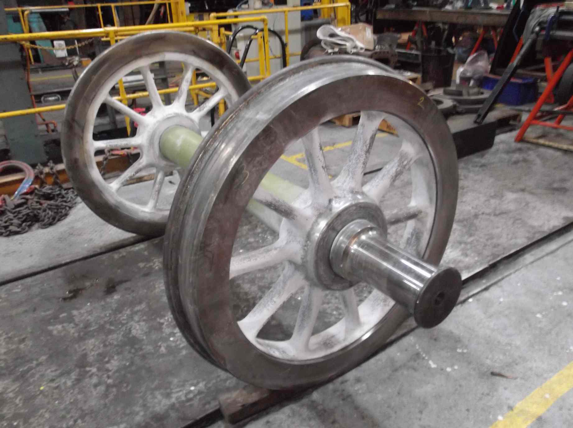
The Cartazzi wheelset has now been removed from the frames. There was just enough room in the workshop to move the tender forward and get the Cartazzi on to the wheeldrop. A couple of pipes had to be removed, not greeted enthusiastically by the pipe fitting team. It was all a relatively straight forward operation by a well-practised team.
The wheelset was lowered just enough to get the top plates off then lowered to the bottom of the pit where the axleboxes were removed and lifted out. The wheelset and its components are now being examined. The left outer hornstay shows markings suggesting that in its history it had been fitted to locos 2548 (Galtee More), 2572 (St. Gatien) and R-LNE-2565 (Merry Hampton), the latter looking like the first stamping.
As soon as the axleboxes were out they were taken to the prep pit and power washed while the other components are bing dealt with in the workshop. Components are being needle gunned and cleaned, and a number have already been di-pen inspected. Dimensional checks are now being carried out to check for wear and to determine the dimensions for the refurbishment of the bearings.
Weeks commencing 25 November and 2 and 9 December
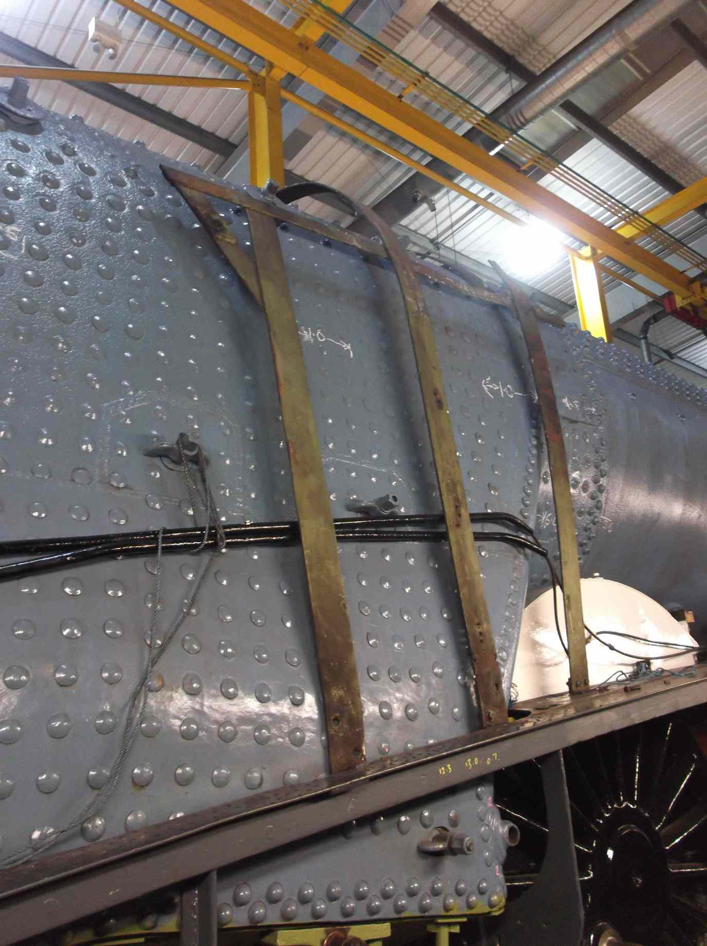
The backhead cladding has been tried in position. The cladding is fixed on studs in bosses welded to the boiler plates. Some of these studs had been broken off so the bosses had to be drilled out, re-tapped and new studs fitted. The cladding isn’t in very good condition and has a number of patches where sections were cut out and pop-riveted back in to allow access to repairs to the boiler back plate. The pop rivets have now been removed and the patches will be welded back in.
The boiler insulation is now on order. The crinoline that goes over the firebox has been temporarily put on to locate the securing brackets cut off as they were foul of the boiler. Clearance is tight on these so the screw holes will be welded up and tapped out.
Also at the back of the loco work continues on the Cartazzi. Various components have been cleaned and examined. The rubber springs were removed from their boxes and are life-expired. New rubbers are now on order. The Cartazzi hornstays have been tested and one is found to be cracked. This is a cast component and will require repair.
The measurement and assessment of the Cartazzi axleboxes, horns and bearings is ongoing. One of the bearings is damaged and shows cracking so will require replacement. The bronze wedges show wear and movement of their centres due to this wear. It is estimated that there is sufficient material in the existing castings to machine to correct the centre offset and to remove the wear.
The Cartazzi wheelset has been stripped back to metal. This has allowed it to be MPI examined by contractors, declaring it free from defects. After test the wheelset was again cleaned down prior to prime painting.
The NDT contractors also examined the inside connecting rod and strap as required by our “VAB”. No defects were found.
The Cartazzi frames have also seen work. The frames have been needle gunned. This has allowed them to be examined and tested. No faults have been found and all the unloaded rivets in the spring hanger brackets are tight. The outer Cartazzi frames are now painted to undercoat.
The boiler expansion brackets have now been fitted. The last one on the right had a shim plate machined and fitted. Fitting this allowed the last ashpan cotter to be fitted. The ashpan sprinker bulkhead fittings just above the top of the diaphragm plate have been fitted.
The centre of the boiler barrel is supported by a pad on the top of a frame stretcher. This is shimmed to support the boiler. The shim has been fitted and secured. The damper door and spark screen have been refitted.
At the front of the loco the piping team have been running in the atomiser pipework as they have been unable to progress the re-installation of the cab pipework due to the cladding fitting.
The steam supply pipework to the atomisers is now in place. It’s a bit vulnerable and has seen damage so is now being repaired. Inside the smokebox there is a lubrication pipe to the middle cylinder and the fitting goes in to the top of the cylinder. The fitting was a poor fit and this area was saturated with oil when the concrete was removed, so the face of the cylinder casting has been worked on until we can be sure we get a good seal. The pipe to the fitting runs around the outside of the saddle and this has now been run in.
The last of the loco brake gear has now returned to the workshop. The arms that connect the leading brake cylinders to the leading brakeshaft have been examined and are free from defects and all the smaller links have been stripped. Each remaining bush and pin is being measured so new can be made as required.
The loco brake hangers have had their thickness rebuilt with weld. All six hangers have had the welded areas machined to give the dimensions shown on the LNER drawing.
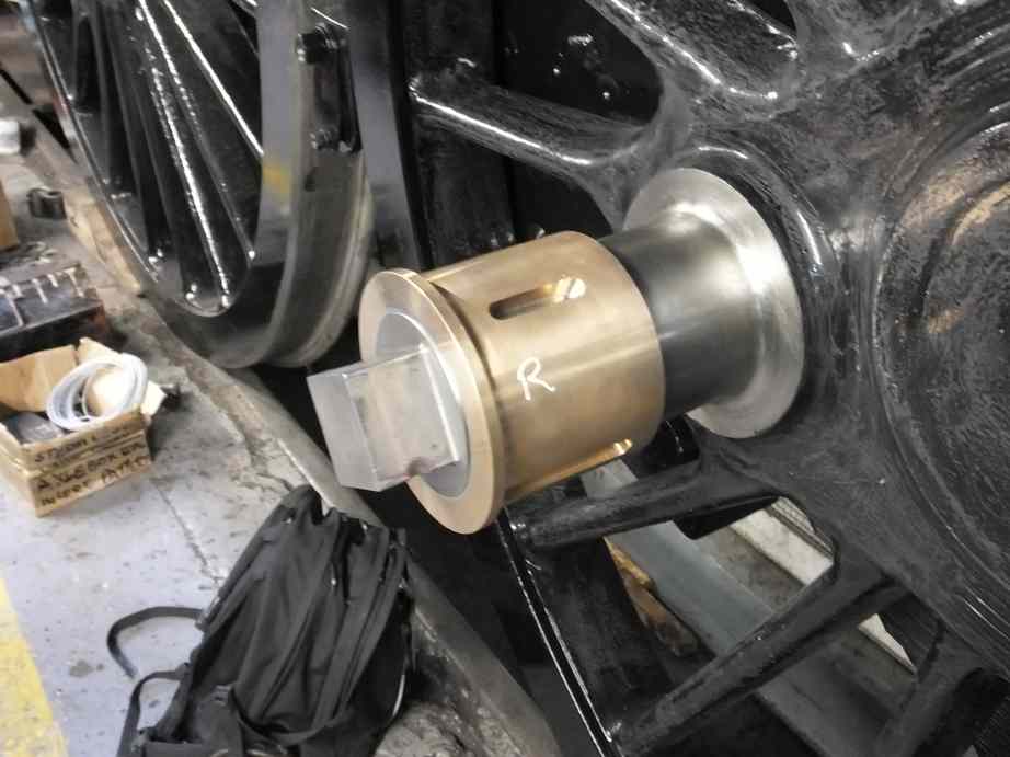
The outside big end bushes have been white metalled and machined by contractors and are now back at York. With the side rod bushes they have been checked over and keys are being fitted. Some of the old keys are being reused after adjustment, but new keys will also have to be made.
The knuckle pins and the holes in the rods have been revisited. The holes were dressed and measured to check on the tapers and roundness. The knuckle pins have been examined and tried in. They are not a good fit. We had previously condemned one and now the decision had been made to replace both, the material cost not being excessive. Blanks are now on order and will be finish machined at York to match the rods. New bronze for the knuckle pin bushes has been obtained.
New bronze for the gudgeon pin bushes is also at York and the first has been on the lathe for roughing out. There is a mix of bronze and steel bushes in the conjugated gear, and they new are now being machined and fitted.
The new key for the LH gudgeon pin has been made and fitted. This has allowed the LH crosshead to be fitted and allowed the final fitting of the LH lower slidebars. The new bushes in the crosshead drop links have been drilled through for their lubrication holes.
Our new valve guide, to replace one found cracked through, has now been machined by contractors, and a lovely job it is too. It now requires careful fitting to the valve cover. Bushes are being made so that the holes in the cover can be accurately drilled through to the guide.
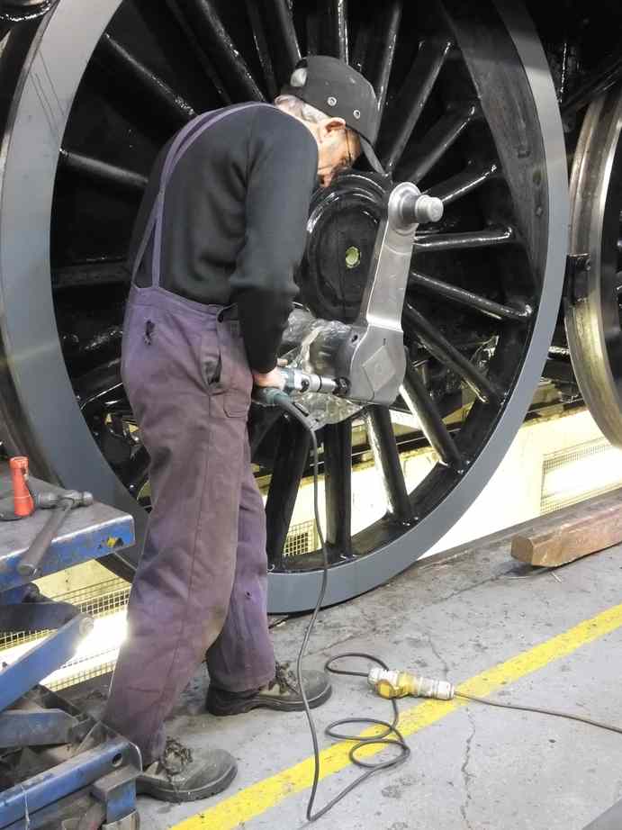
The fitting of the return cranks by an Engineering Team member has now been completed. This has been a very skilful job and the volunteer should be proud of the work he has done on these key components. After finishing them on to the crankpin squares the bolt holes and taper pin holes were reamed out. We did not have the size of reamer required so at short notice another of our volunteers sorted out the purchase of one at a bargain price.
Work continues on the tender. The new upper plate for the tender front has been countersunk and fitted in the tender. The reinforcing lifting squares have been welded in place.
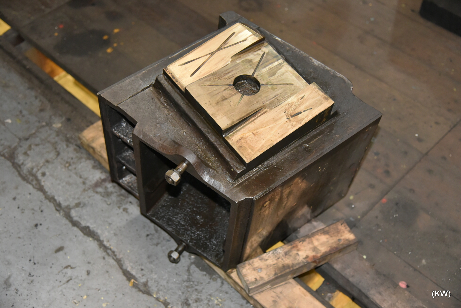
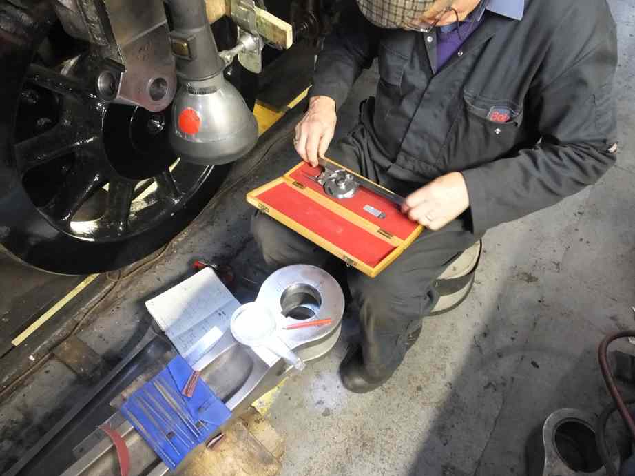
The coupling that connects the loco to the tender varies from the BR drawing, as did the loco front coupling. We seem to have a rubber spring on the coupling perhaps from another type of loco. We have no knowledge of it ever being changed so it has proved to be satisfactory in service. The drawing gives details of loading and compression so the spring was put on the hydraulic press to measure the load that the spring really gives. This information will be used to rationalise the collection of rather rough looking plates and washers used as spacers on the coupling bar, and to set the correct pre-load.
The OTMR sensors have been away for calibration. The results have been complied on a spreadsheet and will be sent to our “VAB” for acceptance before refitting.
Away from York, the coach has now left Cranmore and has been transported to Margate for secure, under cover storage, until the overhaul of the running gear can be organised.
This is the 46th update—you can read all the previous instalments here.
when is it going to be back on nymr
This highly informative blog provides a welcome update; thanks Darrin for keeping it going. You and your team of highly skilled volunteers are doing a great job in giving this iconic loco a new lease of life.