Weeks commencing 12 and 19 August
With the tender axlebox bearings all now ready for fitting, the tender frames are ready to be lowered on to the axleboxes and wheelsets. The tender axlebox rubber seals that seal against the wheels have now all been fitted and the only outstanding piping job—the lagging of the steam heat—has now been completed.
We are in discussion with suppliers for the hire of the necessary equipment but so far they have been unable to give us a date to collect from their depot. After the frames are on the wheels there will inevitably be some de-snagging then the tank will be refitted. Fasteners for the tank are on order.
The plan for the tender frames and tank lift is being developed and the risk assessment is at draft stage, being circulated amongst the Risk Assessment team.
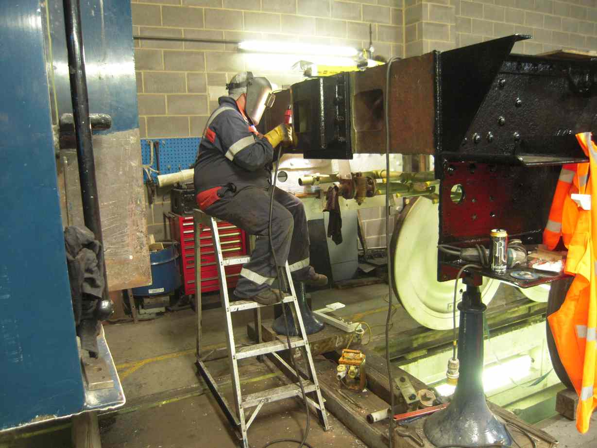
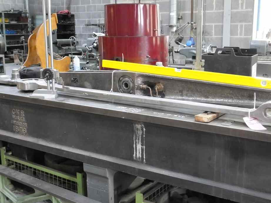
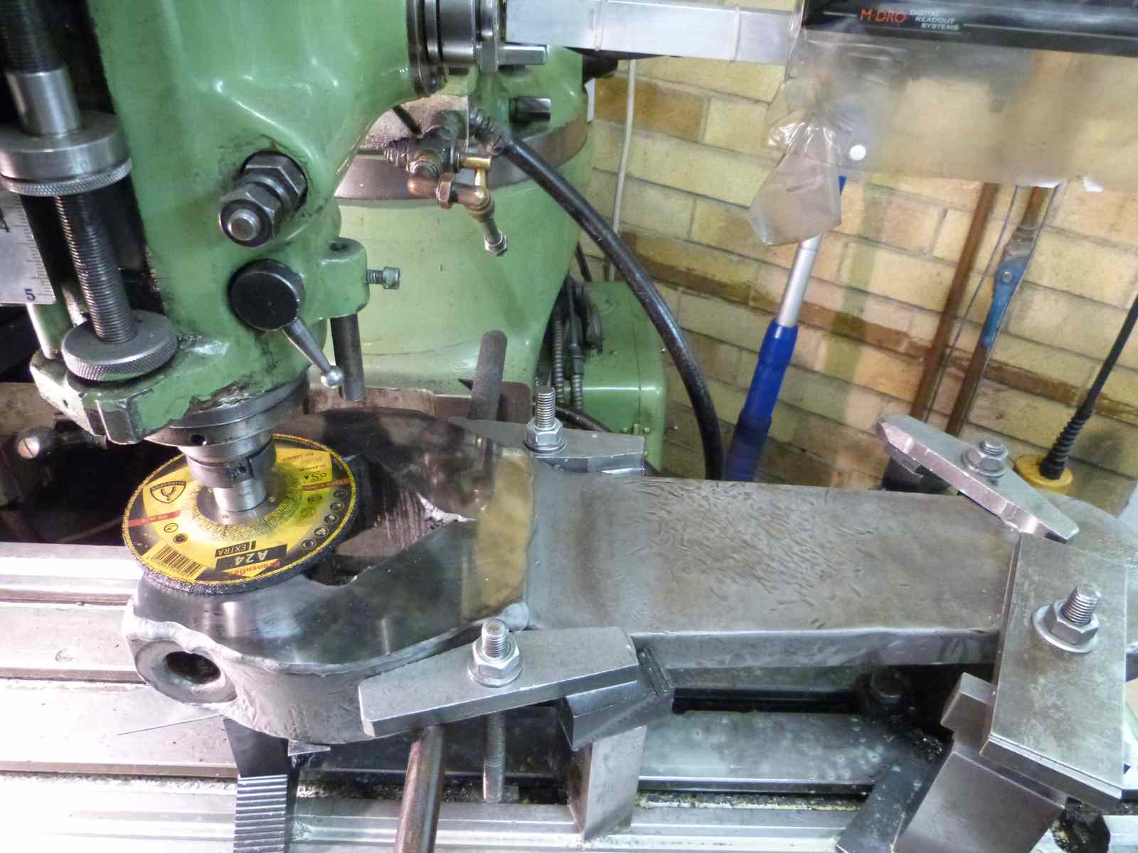
During the assessment and test of the leading tender dragbox it was decided that the material thickness around the safety link holes should be rebuilt. This is best done before the refitting of the tender tank so we have now had a contract welder in to do the work. To minimise the amount of time the welder has to spend on site we ground round the areas to prepare it for welding.
While on site, the welder also repaired the valve chest cover that was found to be cracked during its examination.
Meanwhile the tender brake and suspension components have been painted. These components being easier to fit to the tender frames before the fitting of the tank. The tender springs were mounted on the tender frames and then the spring hangers put up.
The tender frames have now been painted to gloss and varnished. The last patches under the tender tank, inaccessible until the front end beam was moved for the fitting of the vacuum brake cylinders, has also been painted to top coat.
At the front of the tender tank the flanges wasted away that connected the front plate to the tank in the coal space have been drilled and are being welded in place. The front plates are being bolted to these flanges. The last corridor roof section has now been fitted and trimmed to meet the back of the front plate. This was not easy as the existing corridor slopes down toward the cab end. Good alignment has been achieved with the existing lower section of the corridor.
The wooden template for the top section has been refitted and aligns very well with the new corridor roof.
Also on the front plate, the cutout where the scoop indicator pipe comes through was drilled and tapped so the indicator and cover plates can be refitted.
On the outside of the corridor the mammoth grinding job of removing the streamlining weld that ran the length of the tender to the water filler space bulkhead has been completed. The burring out the holes along the tender tank rear flange that were welded up to reduce their size to specification has also been completed.
Meanwhile welded patches have also been put in behind the corroded and holed plates around the tank left hand top beading.
At the back of the tender, the vestibule handrail has been finished and it has now received a coat of primer. Looks like new. At the bottom of the vestibule work continued plugging bitumen leaks.
Work on the ‘cod’s mouth’ gear continues with new bronze bushes being made for the horizontal shaft. Some final fitting is required. There is some damage to threads and other minor components which is being worked through.
The middle slidebar bolts are now completed and ready for fitting. All the others are drilled for feather key fitting, with some now done. It has been decided that one further existing bolt should be replaced. A new bolt has now been roughed out.
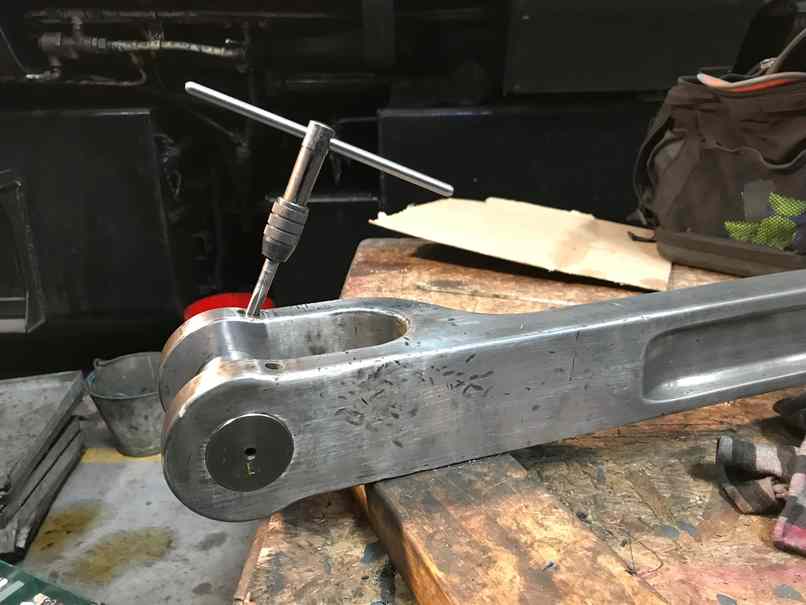
The pinning of the outside valve gear continues with all the outside pins now fitted. The pins that require locating with taper pins are now being drilled or notched and reamed for pins. A new bronze bush has been made for one of the combination levers and this has been pressed in. The dimensions of the taper pin holes have been measured and the size of the taper pins and reamers we need has been calculated. eBay is now being monitored and one taper reamer already snapped up at a bargain price.
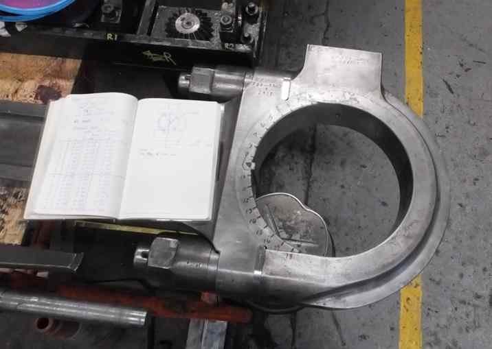
The middle big end bronze castings have now been received and a draft drawing produced of the finished bearing. The gluts that form part of the clamping of the bearing have been surface ground and are being fitted to the big end strap. The machining and metalling, to a procedure specified by us, is now being discussed with a contractor.
The RH eccentric, now part machined was brought in this week as we were concerned that the existing dimensions were not corresponding to the drawing being worked to.
The old RH crankpin square was also retrieved and measured. It was found to be short, which corresponded to the eccentric being thinner than drawing. Only by a very small amount and not impacting significantly on the components strength.
Attention then turned to the specified clearance between the eccentric and the eccentric rod, as the rod sweeps over the eccentric. This clearance is specified on the LNER drawing, and also noted in a BR(E) standing order issued to sheds during the 1950s.
So the eccentric rods were measured and compared to drawings. As our crankpins are new the end squares are full length and with adequate clearances measurable it was decided to add material to the outer face of the eccentric regaining some of the specified thickness. This eccentric is now at subcontractors for rebuilding with weld.
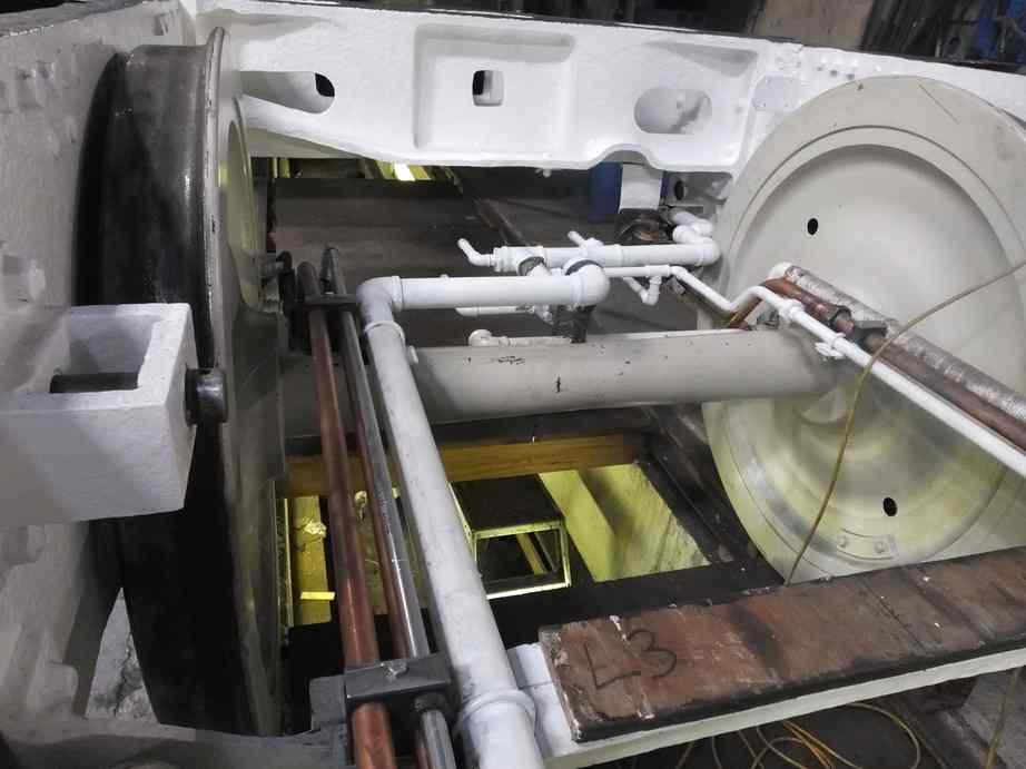
The piping team have been tidying up the tender frames piping as described above, with lagging and clipping, as they will soon have their access much reduced by the fitting of the wheels and tank. They have also requested new bolting for the trailing steam heat flange, this is now on order. Fittings are also being assembled so the steam heat pipework can be pressure tested.
Part of their last activities in the tender frames is the recording of the pipe systems and what new and existing material has been used.
Work also continues on the loco lubrication pipework to the outside slidebars and glands, and to and from the atomisers.
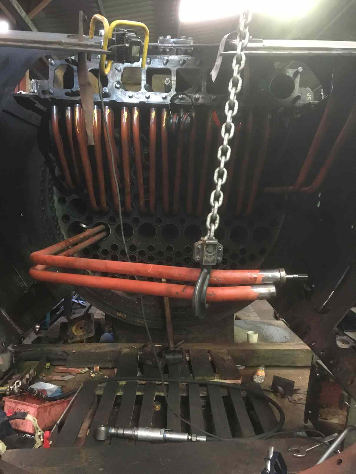
At Llangollen, under the close monitoring of our representative, the superheater elements are being expanded. A number of expanders were sent over from our collection and some borrowed. One difficulty was accessing the end rows. These are accessed through threaded holes sealed by plugs on the top of the superheater.
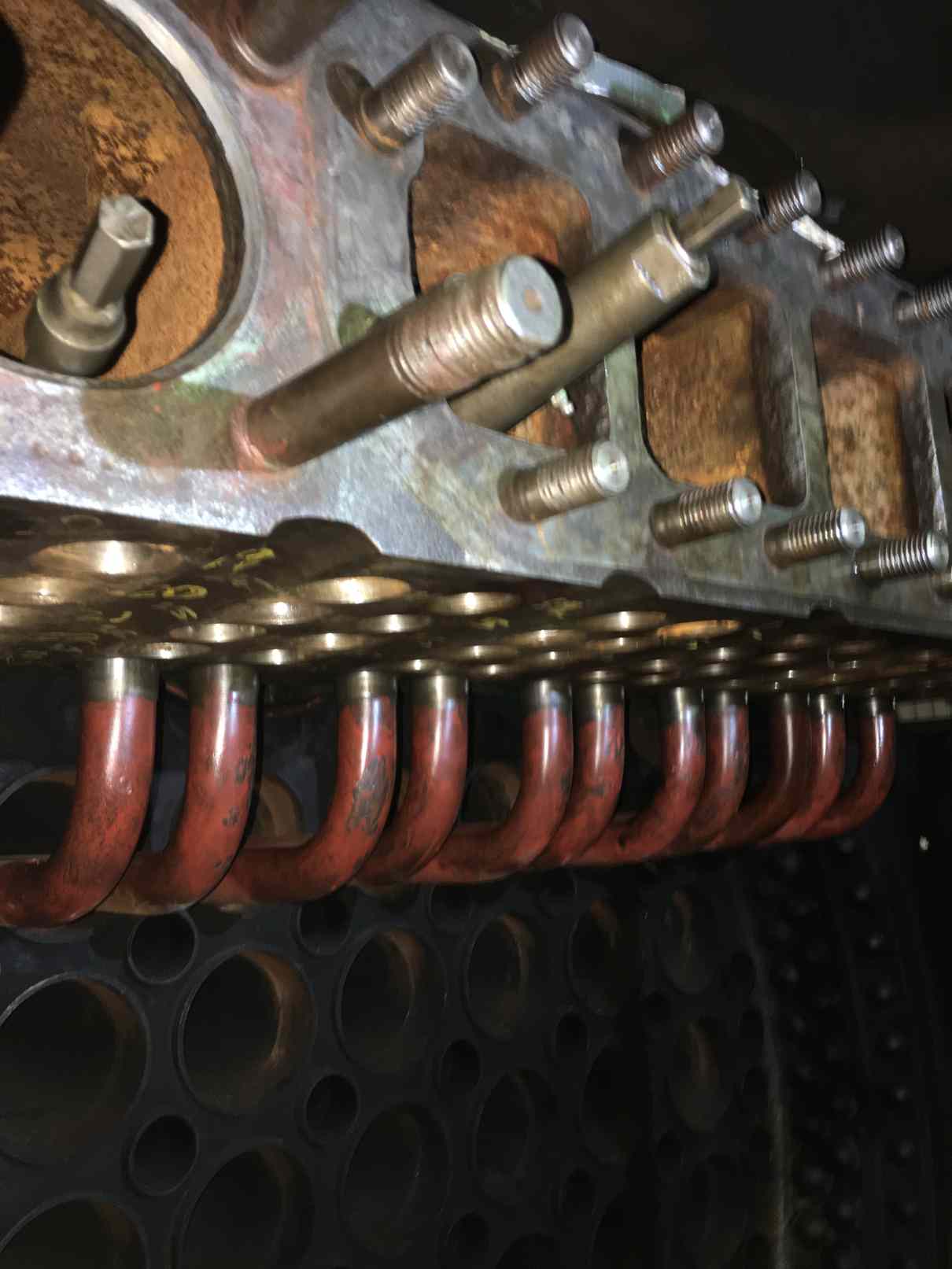
During the refurbishment of the header these holes, requiring repair were welded up and remade to the original dimensions. This would allow the holes to be re-threaded to a larger diameter during future repairs. However, this also meant that expanding the elements below has been made more difficult to access. An extended expander has now been obtained and is now being used.
Weeks commencing 26 August and 2 September
We have been finding it difficult to get a date for the lifting gear hire for lowering the tender frames on to the wheels from our usual supplier, so some other sources were contacted.
Meanwhile, we investigated if we could assemble enough equipment ourselves. After examining what we could get our hands on, and coming up with a safe plan, it was decided that we could do it. So this week the frames were successfully lowered on to the axleboxes. We managed to complete the lift just before the Security team would have locked us out.
Thanks go to the painting team who made sure all the bits that are going to be made inaccessible by the rewheeling, and the fitting of the tank, are getting correctly painted.
Prior to lowering the frames the axleboxes were assembled on the wheelsets and packed to prevent them slipping round the journals, and the vacuum cylinder strap was fitted with new bolts. The axlebox top bearing plates were given a final clean off by our junior volunteers before oiling and fitting.

The wheelsets slotted straight into the frames, even the end sets which are a close fit in the frames. This is a tribute to the volunteer Engineering Team members who did the tender frames and wheelset measurements.
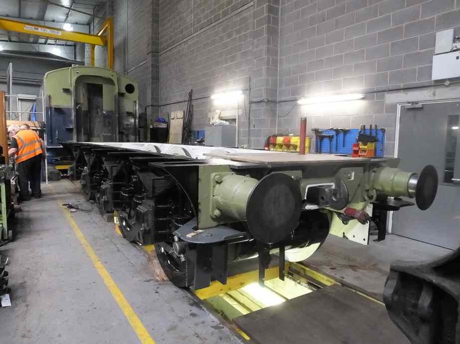
The hornstays were all refitted and are a good fit thanks to their refurbishment. The new hornstay bolts made by our volunteers are also a good fit.
After the frames were down there were no clashes with the pipework or other components in the frames, however the Piping Team leader decided he could increase clearance at the front end of the steam heat pipe, so the pipe clamps were loosened and the pipe was moved slightly. Before the wheels were fitted, the steam heat pipe was pressure-tested and checked for leaks.
The steam heat pipe under the rear tender bufferbeam does not fit the new pipe arrangement, so a new bracket was fabricated. This uses existing holes in the rear drag box, looks like we are returning to a prior arrangement.
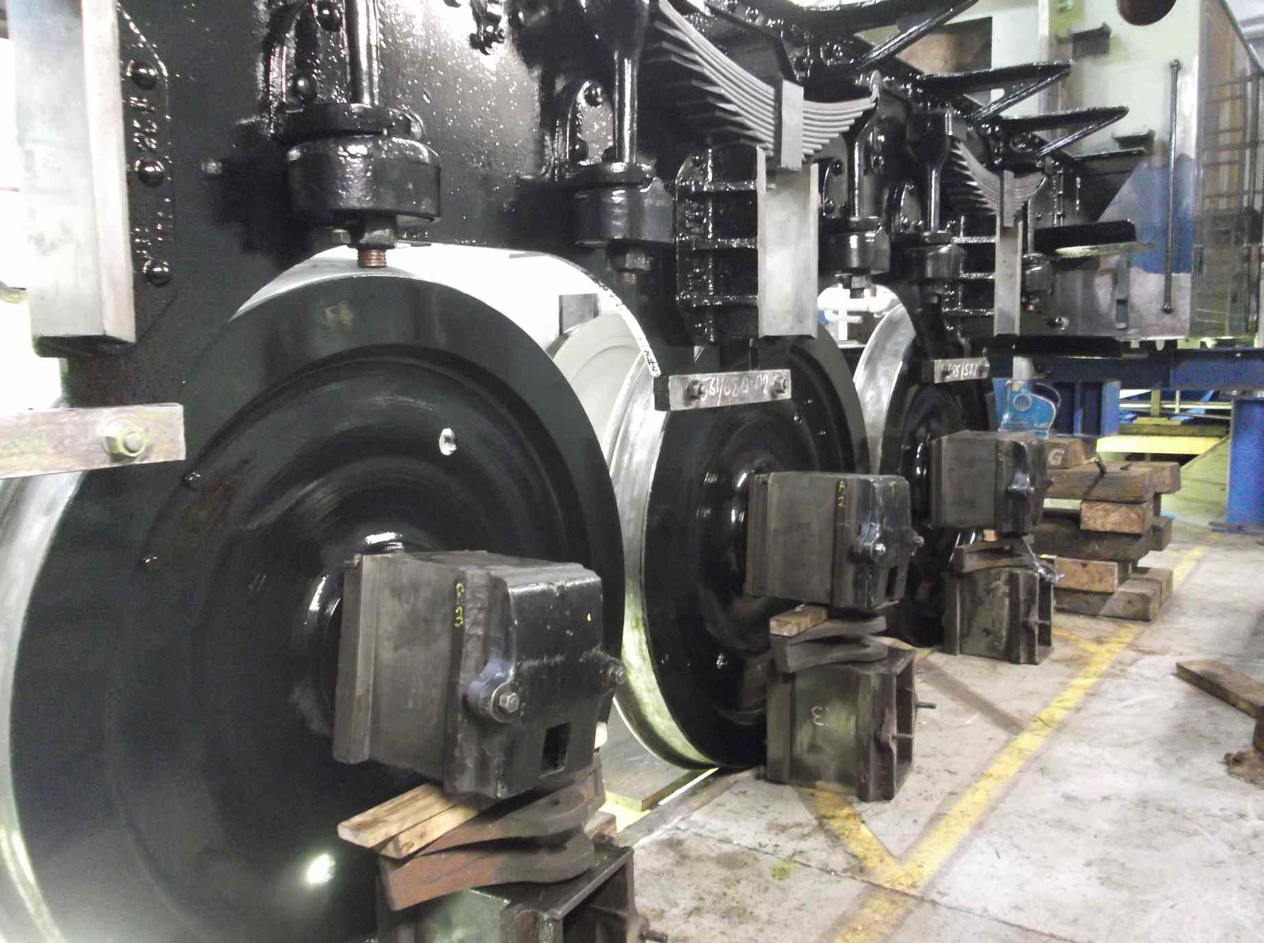
With the frames on the wheels the brake hangers were fitted. The pull rods that run either side of the wheels were also assembled. The transverse tie rods and front brake stay was also fitted and the assembly gently rocked backward and forwards. It’s nice and free. The offsets between the brake block holes and wheel treads have been measured and the distances are consistent. This is important as there is no adjustment or compensation on the tender brake gear to enable the brake blocks to apply equally.
The tender brake pull rods have all rebushed. That allowed the rods to be trial assembled with the lower brake hanger pins. All went together well.
Work progresses on the valve gear and connecting rods. The gluts that space the big end strap off the middle connecting rod have been ground and fitted. The big end bronze casting has been measured to ensure there is enough machining allowance, and the job has been discussed with contractors.
The pinning of the valve gear continues with the fitting of the taper pins to secure the motion pins, now on to the lifting arms.
The feather keys are now all fitted to the slidebar bolts.
The return cranks are in the process of being machined. As mentioned in the last update the machining of the cranks brought up a number of dimensioning anomalies. This has resulted in some further rebuilding of surfaces with weld by contractors.
Further work has been done on the loco front end lubrication pipework, and further recovery of pipe ends and fittings.
Work continues on the front of the tender with the wasted steel from below handbrake shelf level is now being removed.
At Llangollen, all the superheater elements are now in place and the testing of the superheater is now being organised.
This is the 43rd update—you can read all the previous instalments here.