weeks commencing 8 July and 15 July 2019
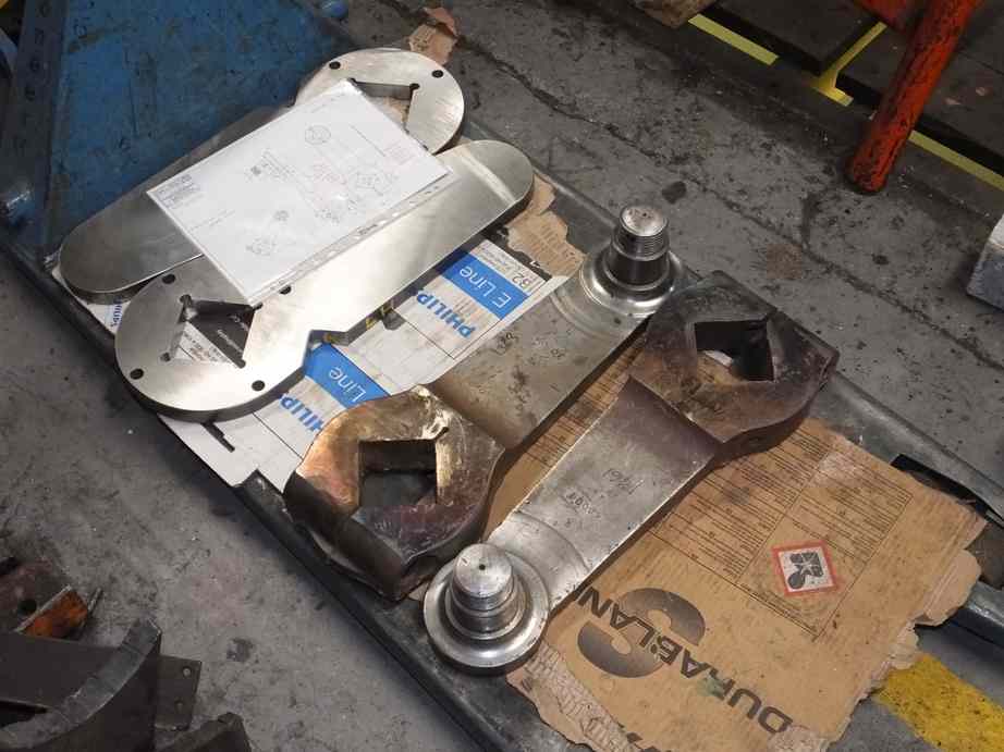
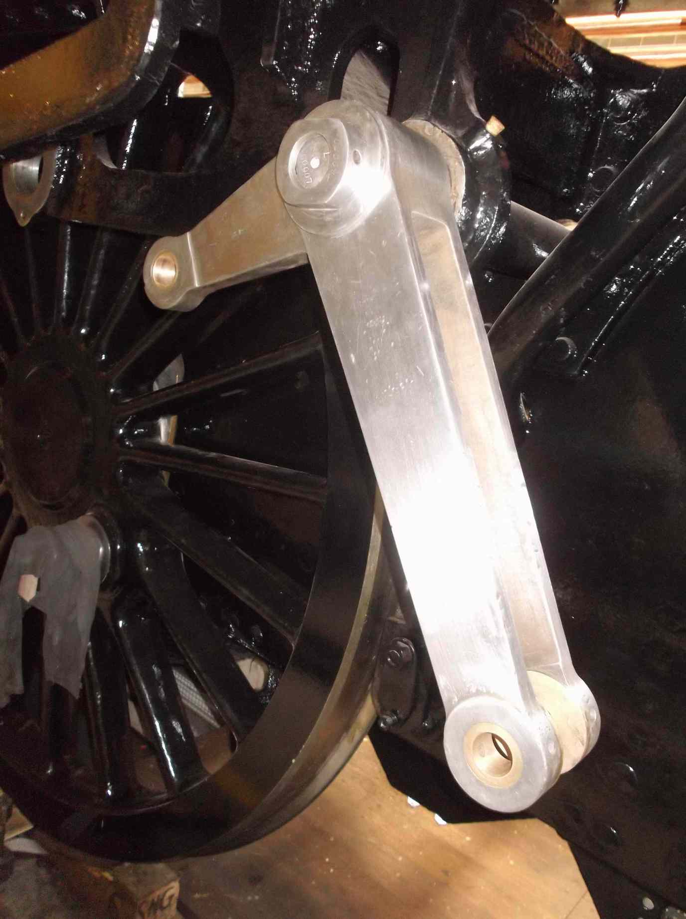
The welded return cranks were collected from contractors and have been returned to York. The crank angle set-up jig has been used to mark the dummy cranks. We were very pleased with how well the jig performed.
The dummy cranks which will provide patterns for machining the real cranks have now been taken to be machined. There’s a considerable amount of machining work to be done on the cranks and the pressure is on to maintain the quality and accuracy so far achieved.
The tender spring hangers are now being painted while the tender frames are receiving black gloss.
The repaired tender spring hangers were returned with NDT documentation covering the repaired areas. That left the hangers not requiring repair and the hook ends of all of them to NDT. So a last round of examinations was carried out, and a crack was found in one of them. The defect was ground out, as surface defects can often be removed on components like these that show a lot of surface history. However, this was definitely a crack and extended into the hanger. It will require repair.
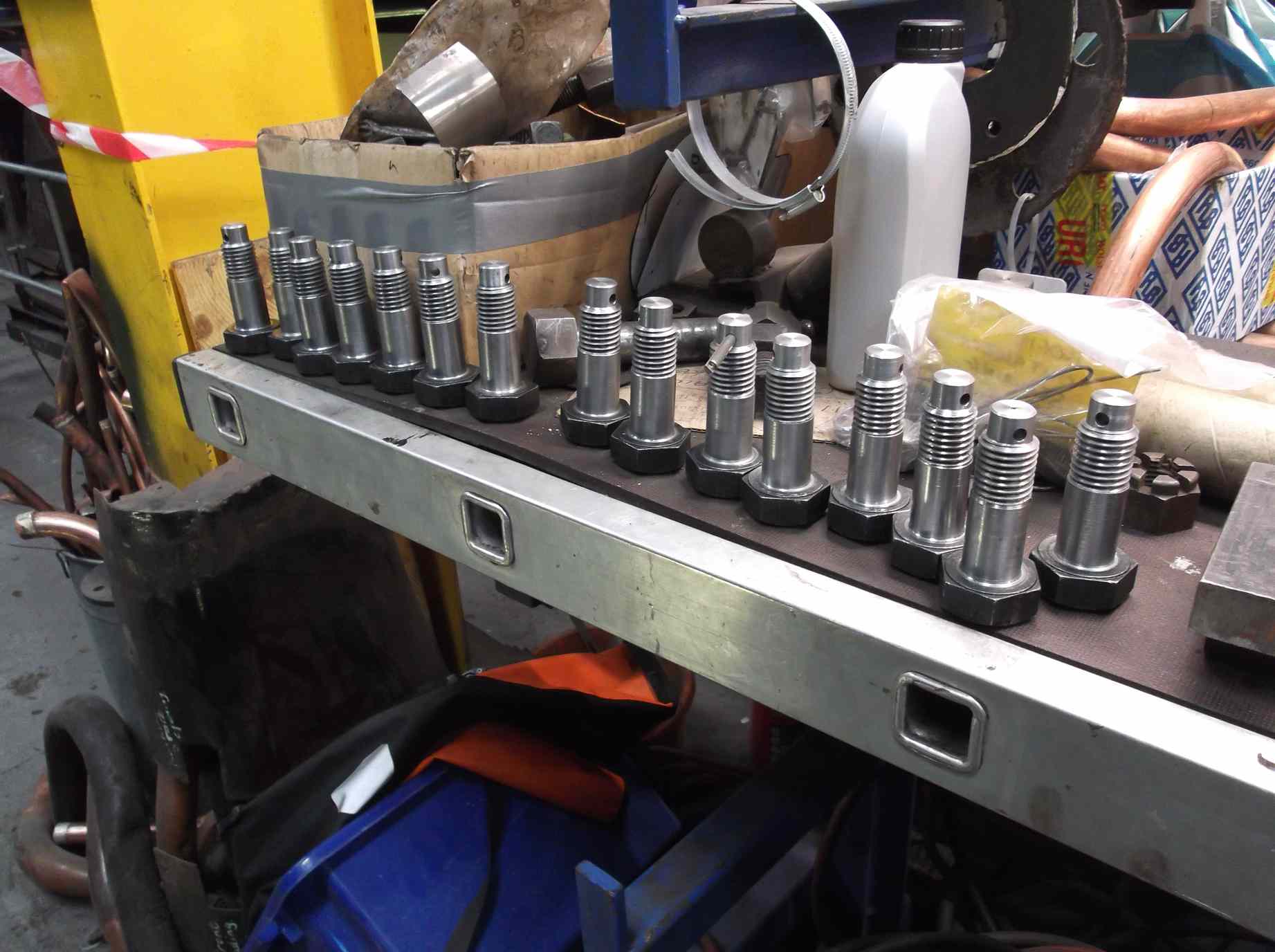
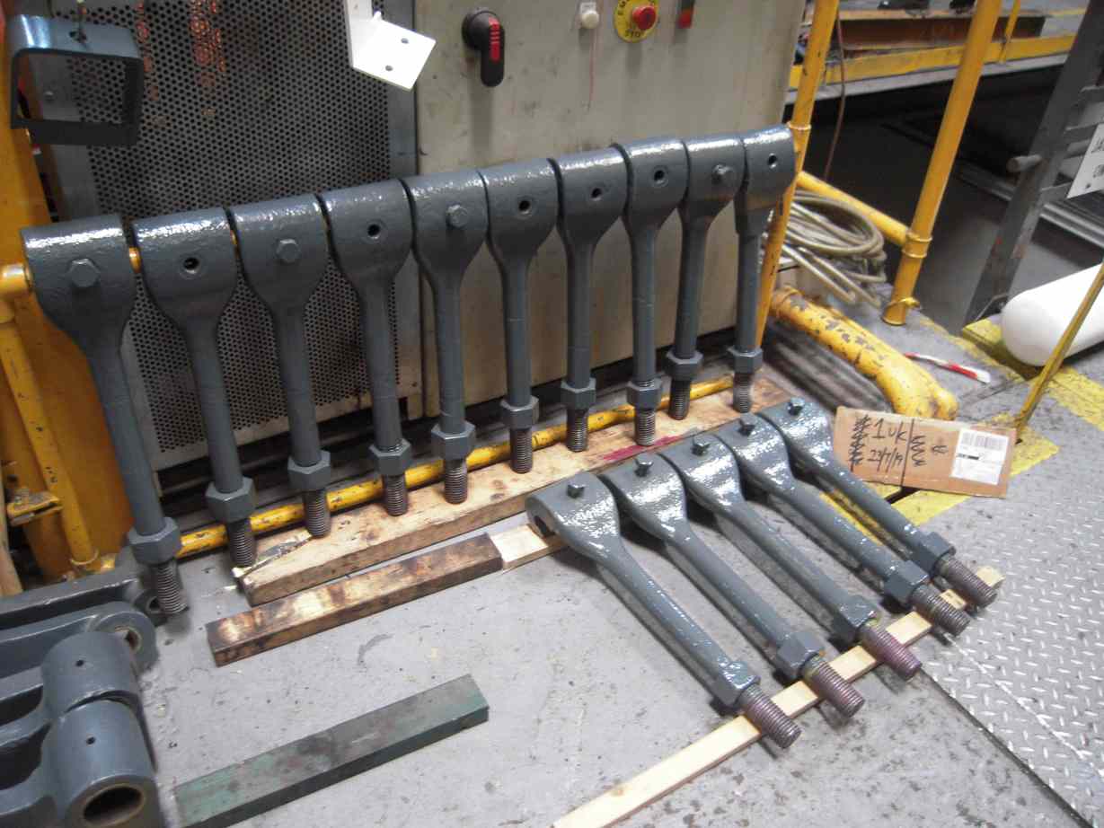
All of the new tender hornstay bolts have been completed with the drilling of the split pin holes.
The tender brasses continue to be scraped onto the journals. Unfortunately two have had to be reworked by contractors as they had excessive end float on the journal.
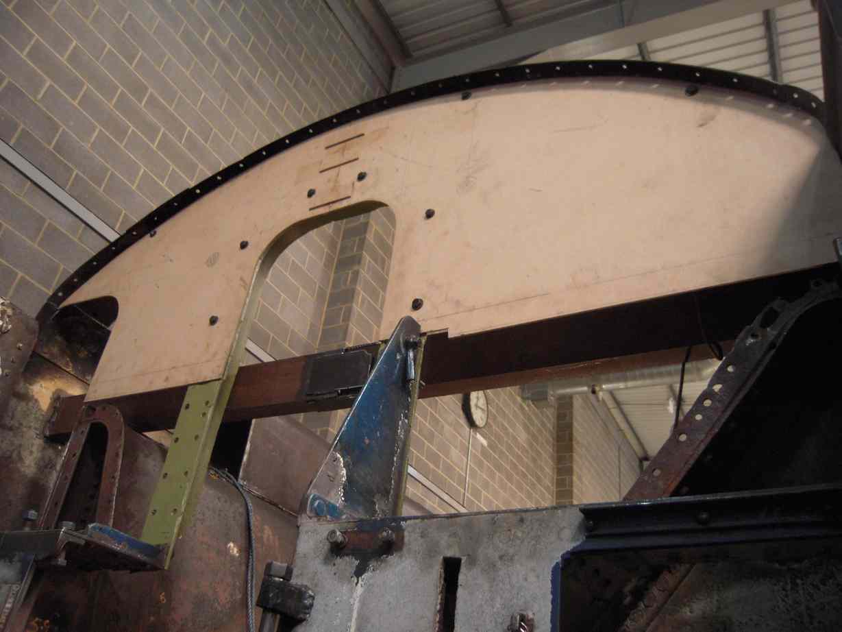
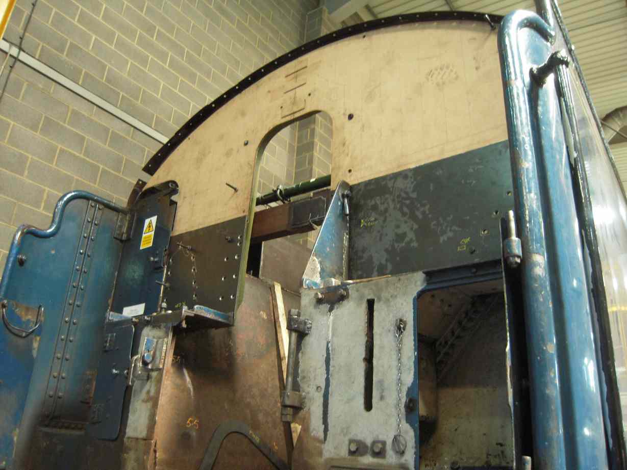
The tender front progresses with the lower two front plates trimmed, drilled and countersunk, while work has started grinding back the long weld that secured the streamlining to the original 1928 tender top. The exposed frame work at the front has been needle-gunned to remove as much of the corrosion as possible.
The butt strap used to increase the height of the front of the tender when streamlined will serve no purpose on the reconstructed tender but will be refitted. The strap was removed complete with all the rivet heads and these have been secured in the strap by welding.
In examining the front of the tender, we noticed that the corridor door appears to have moved and was not closing correctly. We know the tank doesn’t quite sit flat so to make sure we don’t build a twist into it, the beams the tank sits on were re-levelled. The packing the tank sits on was also rearranged to support the tank along the frame line. This didn’t seem to affect the position of the door much, so a string was run along the sides of the tank and we noticed that the tank side definitely bends in toward the front of the right side.
A prop was then put in and jacked out until the door lined up with the exposed framework in the tank. This required the cutting of the beam put to stabilise the front, which was put in before the front plate work was removed. The plates will be fitted to the current shape of the tank but final securing will take place after the tank is fastened down on to the frames, as if we make the front of the tank too rigid now we could end up deforming the frames.
A template has been made of the top section of the tender tank front, and was used to mark the location of the fixing holes. After the prop was put in, the template showed that the holes had shifted, with the tank much more rigid on the side opposite the corridor.
The piping team has been working on running the large diameter air supply pipe and putting in pipe clamps and supports to other pipe runs. Also in the tender frames some final work has been done to the TPWS conduit runs. The OTMR sensor enclosure was weld repaired and has now been drilled for the sensor bulkhead connection holes. The sensor bulkhead fittings have been cleared of contamination and the sensors have been checked. All sensors seem to be doing what they should but they will required formal calibration before refitting.
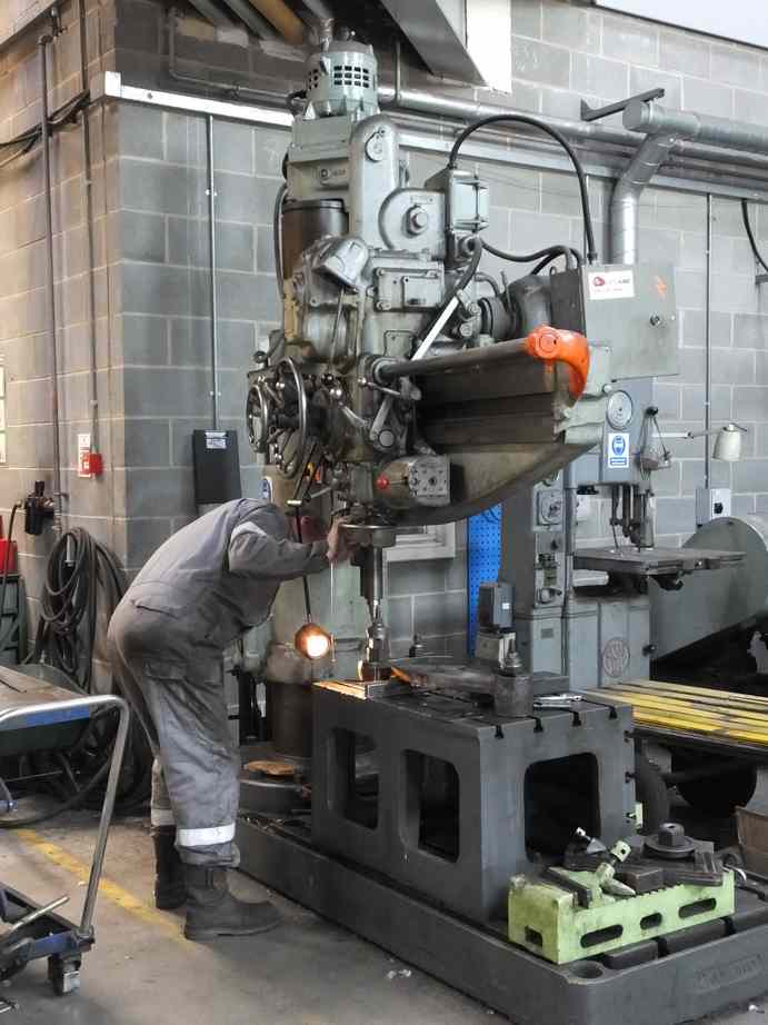
The middle tender vacuum cylinder bracket was positioned and the fixing holes were drilled through. The bracket has now been removed and the holes are being machined for the screws that go through the bracket and hold down the vacuum cylinder trunnions. New screws have also been machined.
The lower vestibule support rod housings are being welded to restore thickness lost to wear.
The first of the loco brake hangers has been rebushed and was clamped to the borer table to examine its straightness, as when on the loco some of the hangers appeared to be twisted. On the table compared to a large square there was some misalignment between the end bushes but it was very small, probably within tolerance. Attention then turned to the trailing pins in the loco frames. These are harder to get at than the others and do show more wear, probably being older. Due to the load on the pin they have worn out of shape and this may be the cause of the apparent twist seen when the loco came out of traffic. We have decided to replace these pins as they are too worn to be trued up and reused.
Work continues on the valve gear with the finishing the fitting of the pin in the reverser column crank. At the other end of the rod the lifting arms and nuts have been cleaned up by dressing out as much of the surface damage as we can without excessive removal of material, or character. The leading pins on the radius rods have also now been fitted and he is now on to the combination levers.

Work on the slidebar bolts continues, with the right side being worked on.
The big end bearing pattern has now been received and was promptly sent to the foundry. They are a little concerned that the pattern won’t give us enough material on the bore to machine to the dimensions we need, so additional work will be required on the pattern before casting.
The strip down, clean and examination of the cods mouth door operating gear continues.
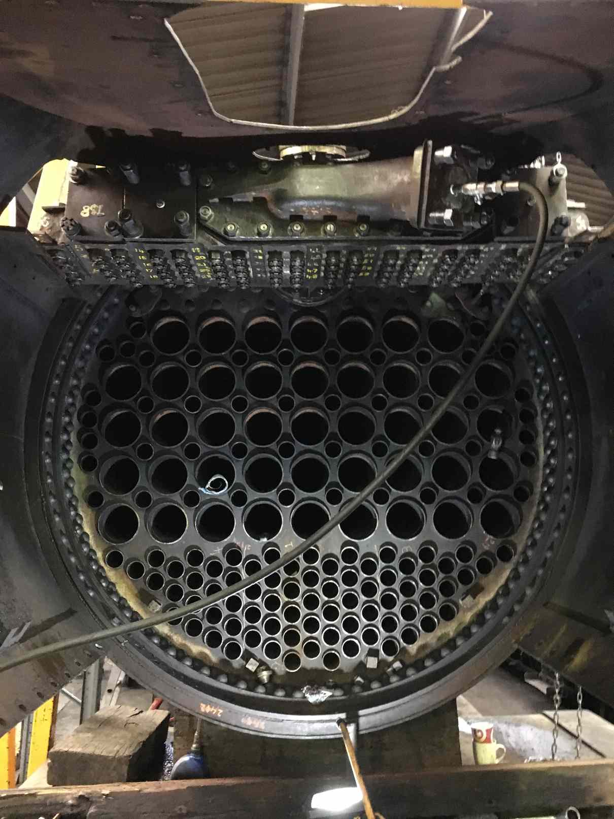
At Llangollen the superheater header is now successfully fitted and has been hydraulically tested in position. This means work can now commence on fitting the superheater elements.
Weeks commencing 22 and 29 July and 5 August
New plate for the tender front has been delivered and is now being fitted. The two lower front plates are now in place. Some new steel pieces have been made to replace various wasted flanges around the front plating. They are being drilled and will be welded in place. The last patch to go in the rear of the tender top has now been welded in place. There is still some work to be done to the outside bottom right of the tender tank where bitumen is slowly oozing out. It is too hazardous to weld near this so it is being mechanically patched.
Meanwhile a new strip was welded to the front top of the ashpan to provide additional sealing against the foundation ring of the boiler.
The old streamlining weld that runs the length of the right-hand tender coal space is being ground away to prepare for the welding-on of new material.
The vestibule handrail complete with its new section is being fitted. The left vertical and top arch are now tacked and the right is ready for tacking.
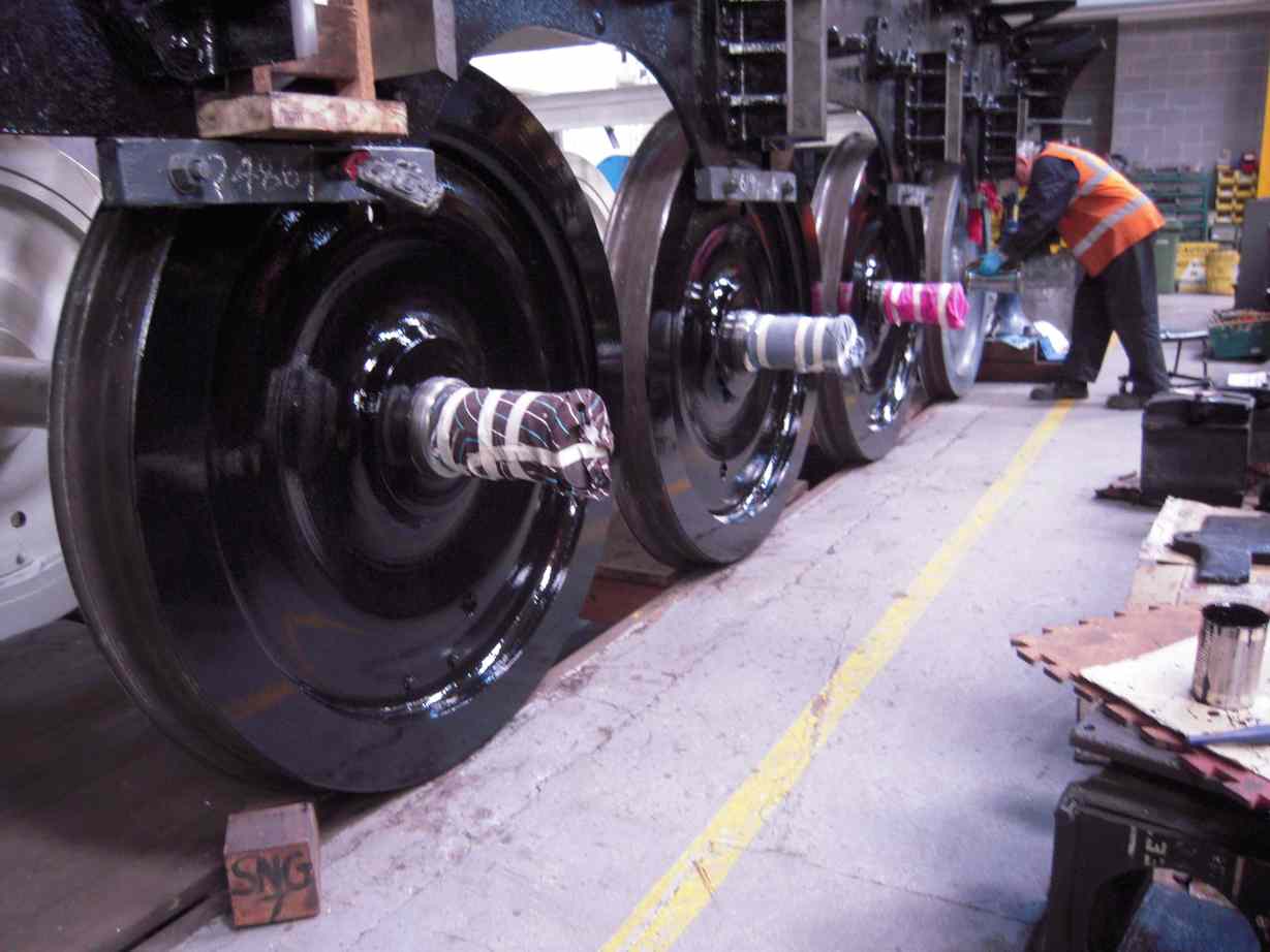
The tender bearing scraping has now been completed. The back of the axleboxes were originally fitted with rubber seals, which fit in a recess in the axlebox, and the recess is drained through holes in the bottom of the axlebox casting. A lot of effort has had to go in cleaning the recess out and unblocking the drain holes. New rubber seals are now being fitted. The left side being completed.
The tender vacuum cylinders have now been refitted on the new mounting brackets. Grease nipples have been fitted and the cylinder trunions greased.
In the tender frames all the pipe runs have now been completed with the routing of the air pipe from the compressor to the reservoir tanks. This is a new run through the frames and at 35mm is a large diameter to find a route for, so well done to the piping team. Attention has now turned to lagging the steam heat pipe.
A new flange has been made for the steam supply to the air pump. This allows full-bore steam supply right up to the pump in heavy-duty steel pipe.
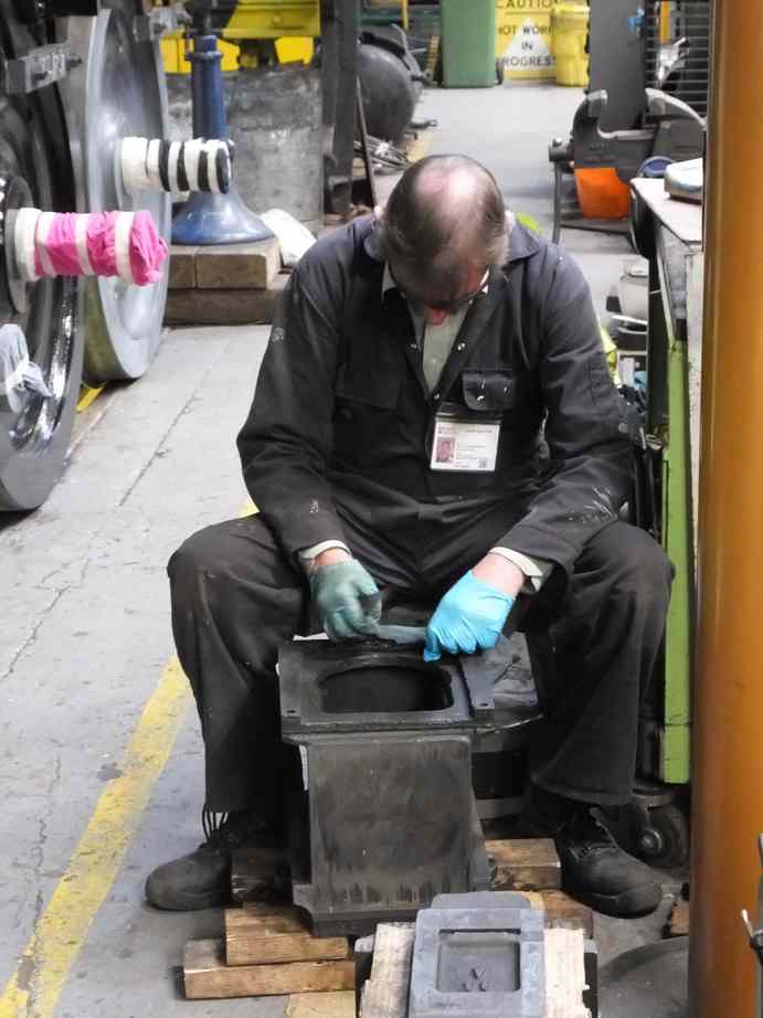
The tender rear bufferbeam steam heat valve has been stripped for overhaul. New stainless steel cotter pins have been purchased for its reassembly.
The spacing blocks for the mounting of the tender vacuum reservoir tanks need to be the correct thickness to clamp the tank tight while supporting the brackets on the tank straps.
Blocks have now been machined to give the correct size and have now been fitted.
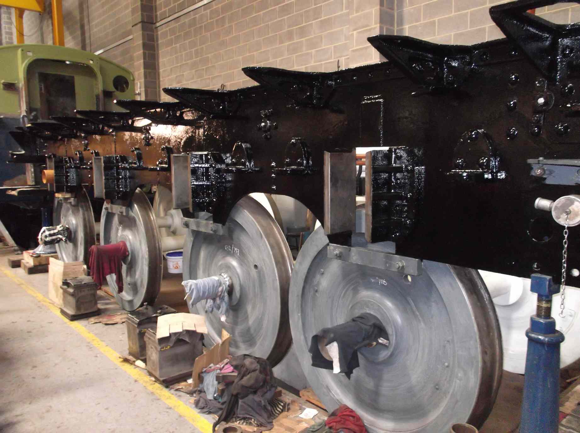
Before the tender tank can be refitted, the frames need to be painted inside as many areas will be inaccessible to the paint brush, so we have been very busy around the frames, while having to stay out of the way of pipe and bearing fitting. The tender spring components are now painted to top coat and are ready for refitting.
The tender lower vestibule support rod brackets have had wasted surfaces rebuilt with weld and are now at contractors for machining.
Work on bushing and drilling the loco brake hangers has continued. The completed hangers have been tried up with the brake beams to check fit, and all appears to be fine.
The assessment of the cod’s-mouth operating gear shows wear to some of the bearings. In traffic it has been found that one of the bronze bearings had become displaced and damaged. This is now in the process of renewal.
Work on the slidebar bolts continues with all the bolts made, trial-fitted and tried in. The heads have been drilled for fitting of the feather keys, to the BR drawings.
Work continues on the fitting of new valve gear pins and bushes to the combination levers.
The return cranks are being machined with the weld recovered back faces receiving attention.
They have now been machined to original dimensions using the crank rod pin as a datum in a special jig we have made.
New guts for the inside big-end bearing assembly have been machined. These will be surface-ground to ensure the correct thickness is achieved to give us the best circular recess for the new bearing. The bearings are on order after modification of the pattern, and are due for delivery to York.
The 2:1 lever overhaul is complete. It was put up on the surface table and examined for deformation, and all appear to be OK. The ball bearings at the fulcrum have been reassembled and greased.
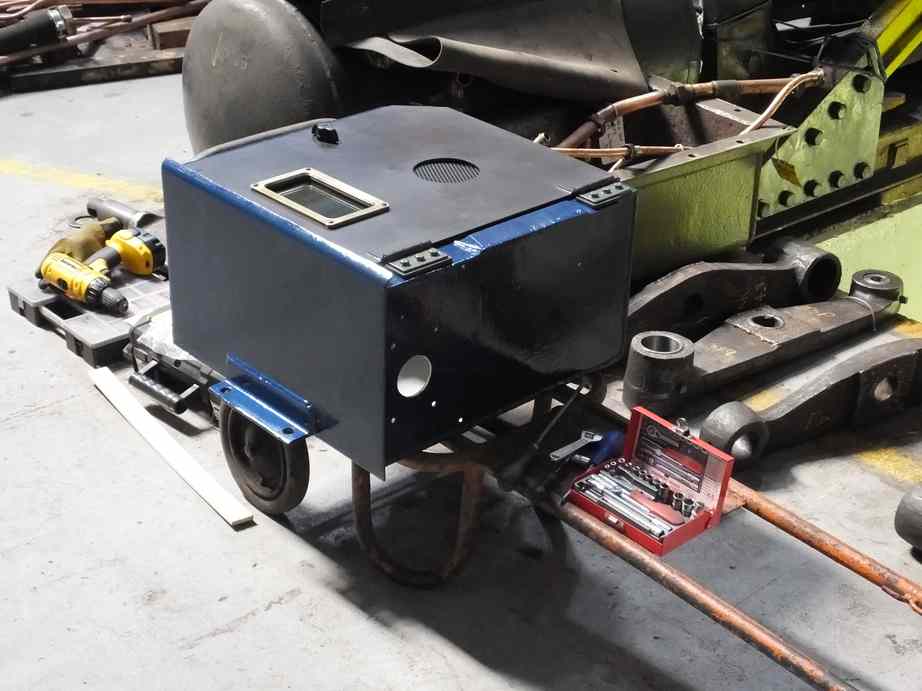
Work on the electrical systems continues. The OTMR sensor box has now been painted after repair, as has its mounting plate. The GSMR radio unit has been reinstalled in its cabinet and the door remounted.
The new battery box is taking shape with a wooden mock up being made. The tender front plate pattern is being altered to accept the battery box.
The piping team are now returning to the loco, and are working on the lubrication pipework around the atomisers and to the valves and slidebars. The atomisers require new cones and these are being progressed. The other lubrication pipework is to be tidied up and will require new brackets and clips. These are made on formers and we have been assembling these.
The replacement steam heat valve that showed porosity during the steam test has been replaced with the new valve now at Llangollen.
The superheater elements are now being fitted with the first row now expanded in place.
This is the 41st update—you can read all the previous instalments here.
where will nigel Gresley be but on the tracks