WEEK COMMENCING 4 March 2019
Large copies of the cast-iron steampipe drawings were sent to the pattern maker this week as he seems to be keen to get the job underway, which is good for us.
The spacers for the safety valve spring caps were finish-machined this week. The valves have now been taken to re-profile the sealing faces to suit the new bottom flanges. This should be the last operation required before the valves are finally assembled.
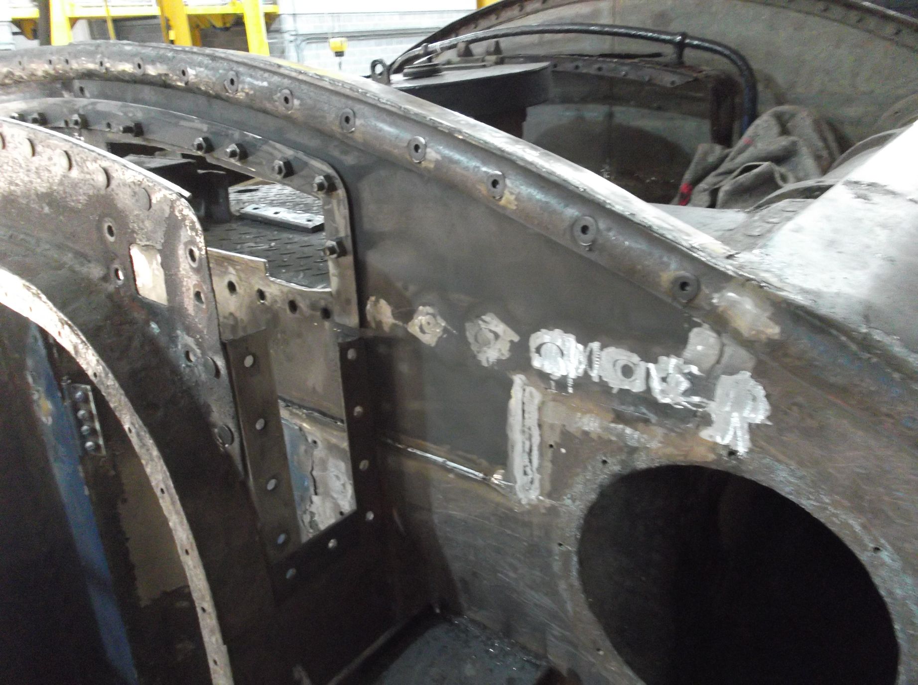
New bolting was obtained this week for the back of the tender as the boilermaking team continue to rebuild the tender tank. The rear beading is now bolted in place, replacing the previous rivets that had to be removed to remove the old, wasted plate. The bolt heads are countersunk and will be hidden when the beading is finished. Elsewhere on the back of the tender the countersunk bolting and new welds are being ground back so that when finished there will be no sign of the work we have done.
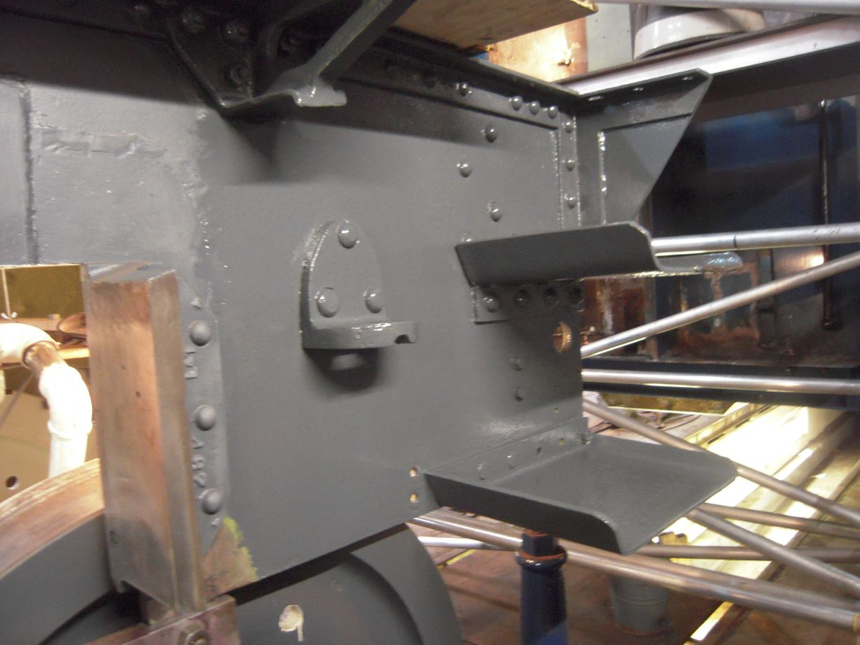
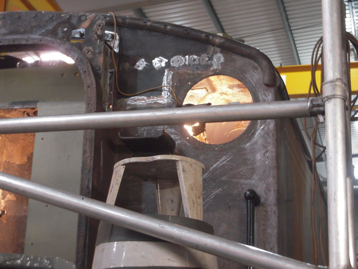
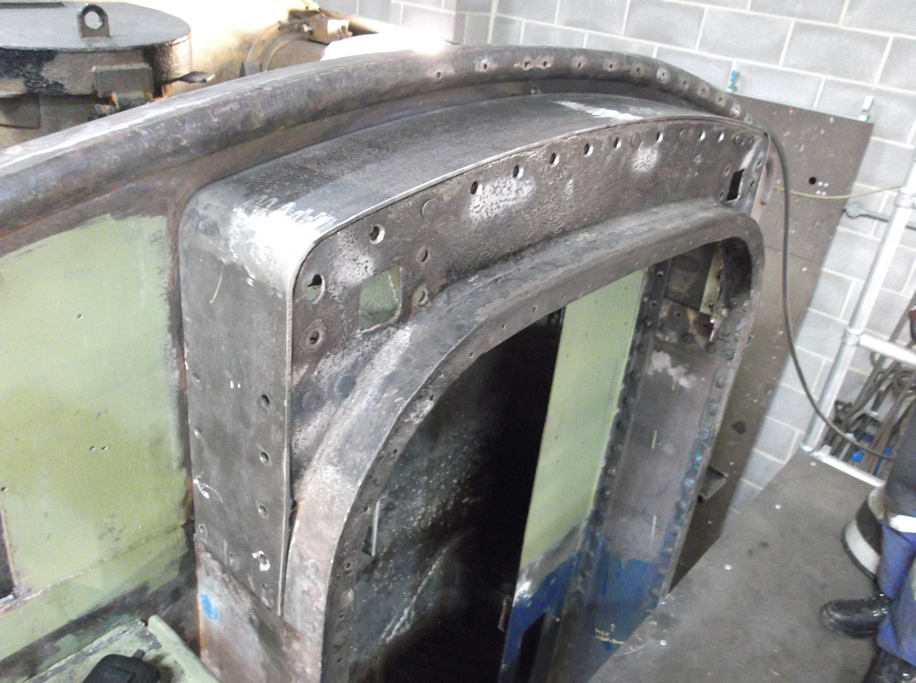
New bolting is also holding the vestibule top arch side flanges in place ready for fitting the shaped top arch plate. This needs to be removable so that access is available to the upper vestibule support components. Inside the vestibule at the top there are support brackets to give rigidity, and these have now been repainted and refitted.
The lower corridor connection support rods that had their square sections built up with weld, have been milled back to square. This has shown up some more areas that need a little more weld and machining.
Inside the frames of the tender the piping team continued their exploration to find a way through for the large diameter vacuum train pipe, clearing the axles and vacuum brake cylinders. It needs to be rerouted to make way for the new routing of the air brake piping and the electrical conduit. It looks like a way has been found. The vacuum reservoir and steam heat pipe runs are on the other side of the frames and new brackets have been put in.
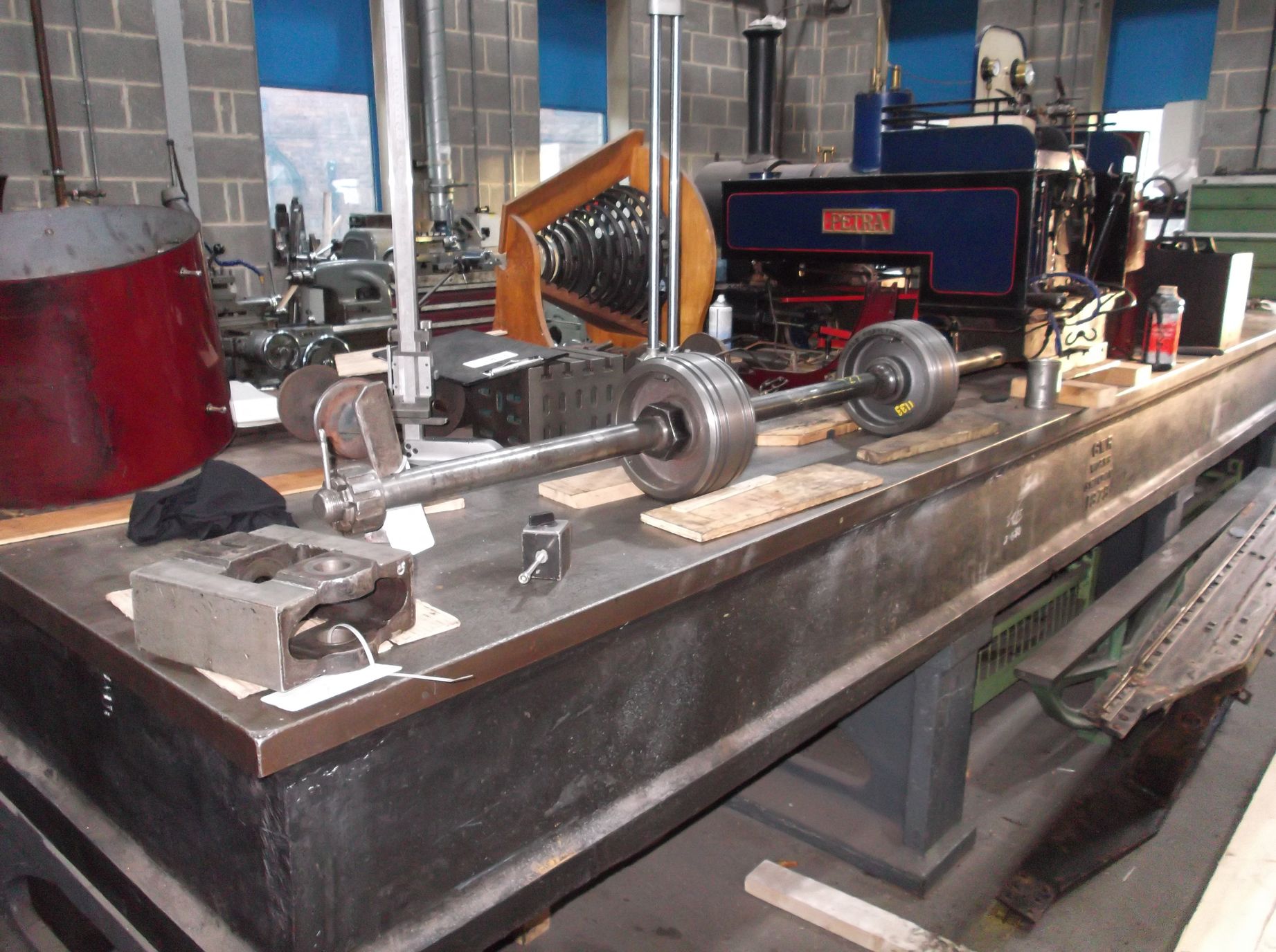
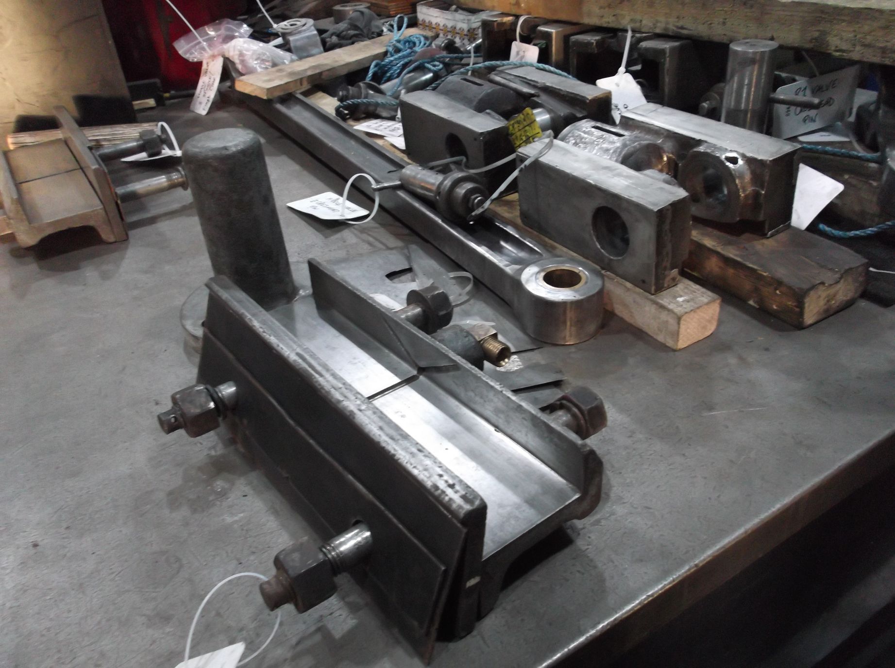
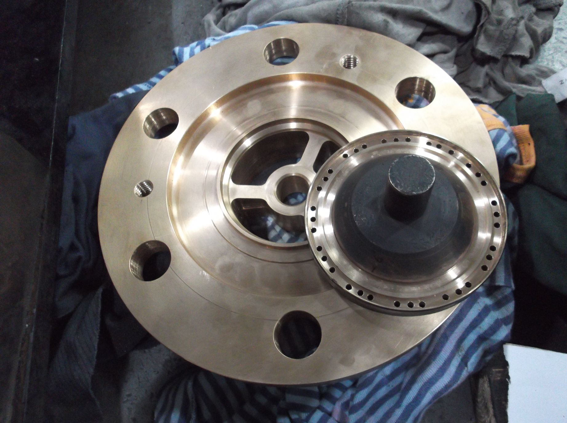
The order has been placed for the new motion pins for the outside valve gear and work continues on the specification for the finished sizes for the connecting rod bushes. The quotations for the tender bearing refurbishment are in, and the order is now placed.
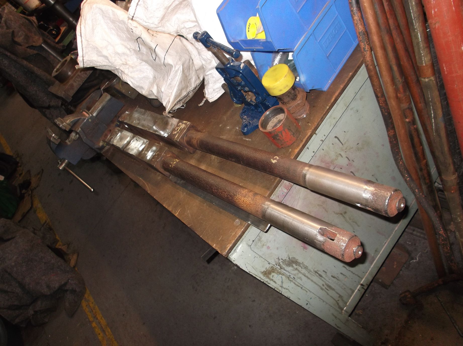
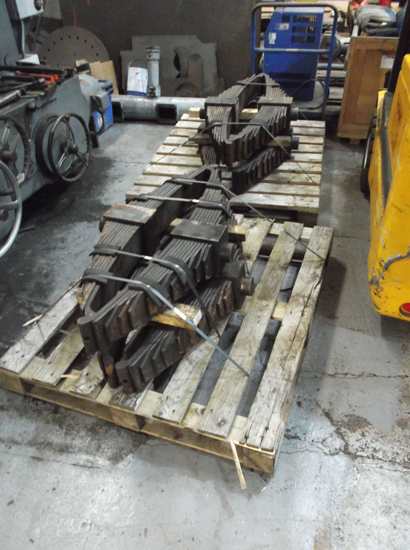
The first two bearings are now with contractors. Work on the tender frames also continues with the repair and fitting of the last tender hornstay. The tender springs are now on pallets ready for banding and then they will be ready to send away for refurbishment. The tender spring hangers have now been examined by our mainline certification authority and we have devised a refurbishment procedure.
Work continued on the tender brake gear with the brake hangers and top pins now being drilled and tapped for grease lubrication. The final lower pins that are reusable have been skimmed and their matched bushed holes reamed to suit.
The survey of the slidebar bolting has been completed and we will soon have a list of the new bolts we will have to make. Work continued on the slidebars measuring all the shims, and their sizes are now being compared to the actual shim thicknesses we need going forward to give us the specified fit on the crossheads.
The examination of the valve crossheads, middle valve and valve guides continued this week. The whitemetal on the crossheads has been examined closely and the thicknesses measured. It looks likely that some repair work is required both to the crossheads and valve guides. Closer examination of the valve guides is ongoing.
The horizontal hornstay fitting continued this week with the last 2 bolts in the right trailing, and all the bolts in the left trailing and both leading hornstays. The job was completed with the drilling of the bolts for pinning and the split pins fitted.
The left driving axlebox scraping has been completed and a start made on the right driving.
When the buckeye coupling was gauged it was found that it opened too wide, so following the BR overhaul procedure, the buckeye body had some small pads of weld applied. These were then carefully ground back to adjust the opening gap to a suitable dimension. A little more work is required to give the knuckle more support so that the gap remains consistent over time.
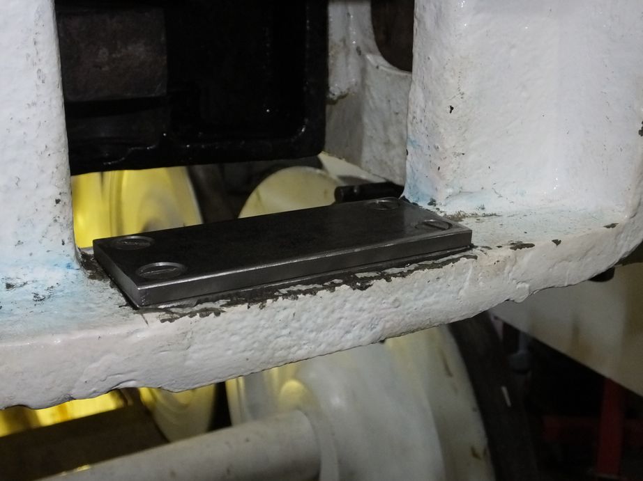
The tender buffer and drawhook offset dimension was measured this week. This required quite a bit of figuring out projecting the centres of the buffers to the scribed centre mark on the hook. After some calculations it was decided that the hook need to go up so it was raised with a jack and a temporary packing piece was put it to hold it up. It will now be remeasured.
At Llangollen that the expansion of the boiler flues tubes is now complete along with the refurbishment of the safety valve pads, and the pad that the manifold seals on. The dome sealing face refurbishment is complete and work continues on the belly door face. A representative of LSL Crewe visited to see the work on the boiler and no issues were raised. At York preparations are being made to send the grate to Llangollen. To get an idea of weight, and therefore transport we will need, examples of the firebars have been weighed. The other components such as grate supports are at York and they are now being collected together.
WEEK COMMENCING 11 March 2019
The new bolting in the tender tank back and beading were ground and the exposed lengths cut back. More of the welding and screw heads were ground flush to give the correct appearance to the back of the tender. The new vestibule arch piece was collected from the supplier this week and a quick run round with the tape measure shows it is to size. The arch flanges are now dressed for welding. The top vestibule strengthening brackets have been painted an are now permanently fitted. Inside the vestibule, the loose paintwork and filler has been removed by the needle-gunned and the area has received a coat of primer.
In the tender frames the pipe fitting team have been running the pipework around the location of the vacuum cylinders. New packings are in the process of being made for the mounting of the vacuum cylinder at the rear of the frames, another congested area that is presenting a challenge.
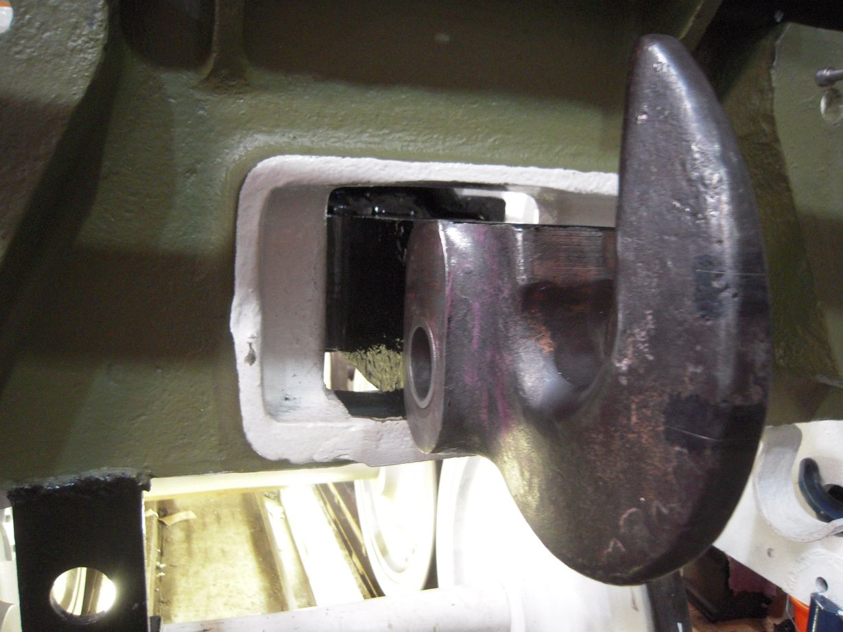
Also at the rear of the tender, the rubbing block for under the coupling hook is being fitted. This now requires machining to set the final height. The buckeye coupling had the pad that sets the opening gap welded, though the buckeye hasn’t yet been reassembled yet to check the gap. The lower vestibule supports received more welding to rebuild thickness as machining showed more was needed. The end cotter slots are being dressed to take out wear. The new welds were ground down to assist machining.
The tender hornstay fitting is now completed and all are now a satisfying knock-in fit, though the bolt holes require reaming and new bolting will have to be obtained. The hornstays were also di-pen tested this week to ensure they are defect free after their weld repairs.
Work continues on the tender brake gear with reaming continuing of the new, bushed brake hangers. One of the hangers had worn at it’s lower end making it considerably narrower than the others. This was built up with weld and has been machined to match the others. The hangers have also been drilled and tapped for grease lubrication.
In the loco frames the gaps between the coupled horns were set before the axleboxes were fitted. These are now being checked. It was found that some of the gaps require a little adjustment. This is done by carefully adjusting the vertical position of the wedge at the leading side of the horns. Meanwhile the coupled axlebox underkeep oil trays are being fitted.
The leading crankpin caps have been removed as they need further machining to allow them to fit correctly, meanwhile a start has been made on machining the loco sidebearer fitted bolts.
The lengths of the coupling rod crankpins have been previously measured but this week we have begun measuring the distance from the wheel to the root of the crankpin so that we can determine any offsets we need to put on the crankpin bushes.
Work continues on scraping the right driving axlebox. We’ve received a few mixed messages about scraping the boxes, whether it’s worth it or not, and whether it was done in BR days or not. Adding to the uncertainty, the BR drawings show that the machining of the boxes changed over the years, which has been interpreted as making the boxes suitable for fitting without scraping. However, there is a BR memo detailing how all axleboxes are to be scraped.
Through the fog of time this week we heard from the horse’s mouth. A former fitter at Kings Cross has been contacted by Peter Townend, former Kings Cross shedmaster, and he has confirmed that all 34A engines from “N2 to A4” were scraped in. The fitter having experience of working on the wheeldrops at King Cross.
Work has started on the testing of the cylinder relief valves. An adaptor has been made accommodating the threaded end of the valve to which the hydraulic pump can be attached. The safety valve valves have been skimmed to restore their profile and await their final fitting.
At Llangollen the last jobs on the boiler are being finished off before final “boxing-up” for hydraulic testing. The grate components at York were collected together and given a clean over to remove any loose debris. They were put near the loading doors by our team of junior volunteers, for collection on Monday. The complete grate should be delivered to Llangollen next week. At the same time the tender springs will be collected and delivered to contractors for overhaul.
WEEKs COMMENCING 18 and 25 March and 1 April 2019
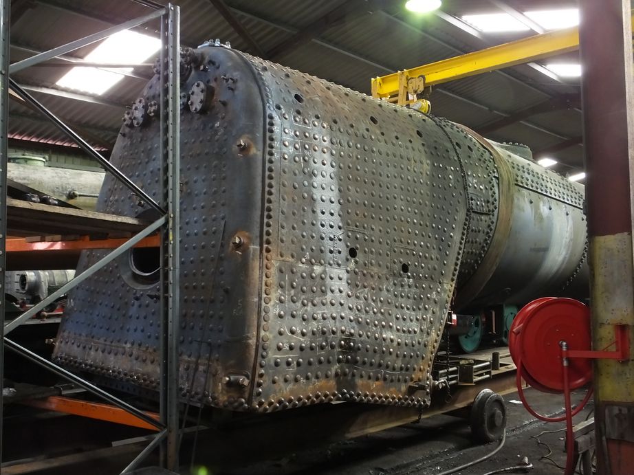
The boiler is now turned upright after completion of the flues and small tubes. The last of the firebox stays which were not accessible on the outside of the boiler when on its side have now been finished. One of the last jobs was finishing the belly door face on the boiler and getting a new seal. The door is now in place and water has been put in the boiler. At the moment only the water legs of the firebox have been filled so that the new sections of firebox wrapper, foundation ring and new staying can be closely examined for any leaks.
At York the safety valves have been lapped in after the valve faces were skimmed. The last step is now to fit the springs.
The tender springs have now been delivered to contractors for overhaul, and the firebox grate components taken to Llangollen from Grosmont and York. The tender spring gear components are now being refurbished with the first two hanger bolts with contractors for repair. A detailed repair procedure has been agreed with them and the first two will be subject to third party NDT.
The bottom plates from the rubber springs on the end of the hanger bolts have now been di-pen inspected. One was broken in 2 when removed from the tender and another has now been found to be cracked. A total of 8 new plates are now on order and all suspect plates will be renewed.
The spacer to get the rear coupling height correct has now been finished and an additional wearing plate has been screwed to the top. The buckeye coupling has been adjusted and should now measure correctly when in the open position. A representative of the UK manufacturers of the buckeye coupling is due to call by over the next few weeks and will gauge the coupling.
The tender brake hanger overhaul continues. There is only one of the lower hanger bushed holes to ream and a new pin has been machined. The fitting of grease nipples is planned for the hangers so they have been drilled and tapped, and nipples bought ready for fitting. The tie rods that go between the lower ends of the brake hangers have been cleaned and descaled and are now ready for inspection.
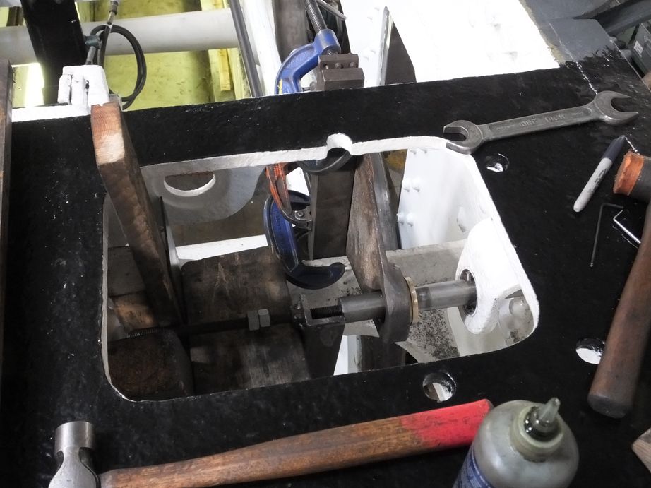
The rearmost tender top brake hanger holes are worn and no longer provide correct alignment so it was decided that they should be bored out along the same centre. The first hole, in the rear dragbox has been successfully bored. The jig now needs re-positioning to bore the corresponding frame hole using a guide in the repaired hole in the dragbox.
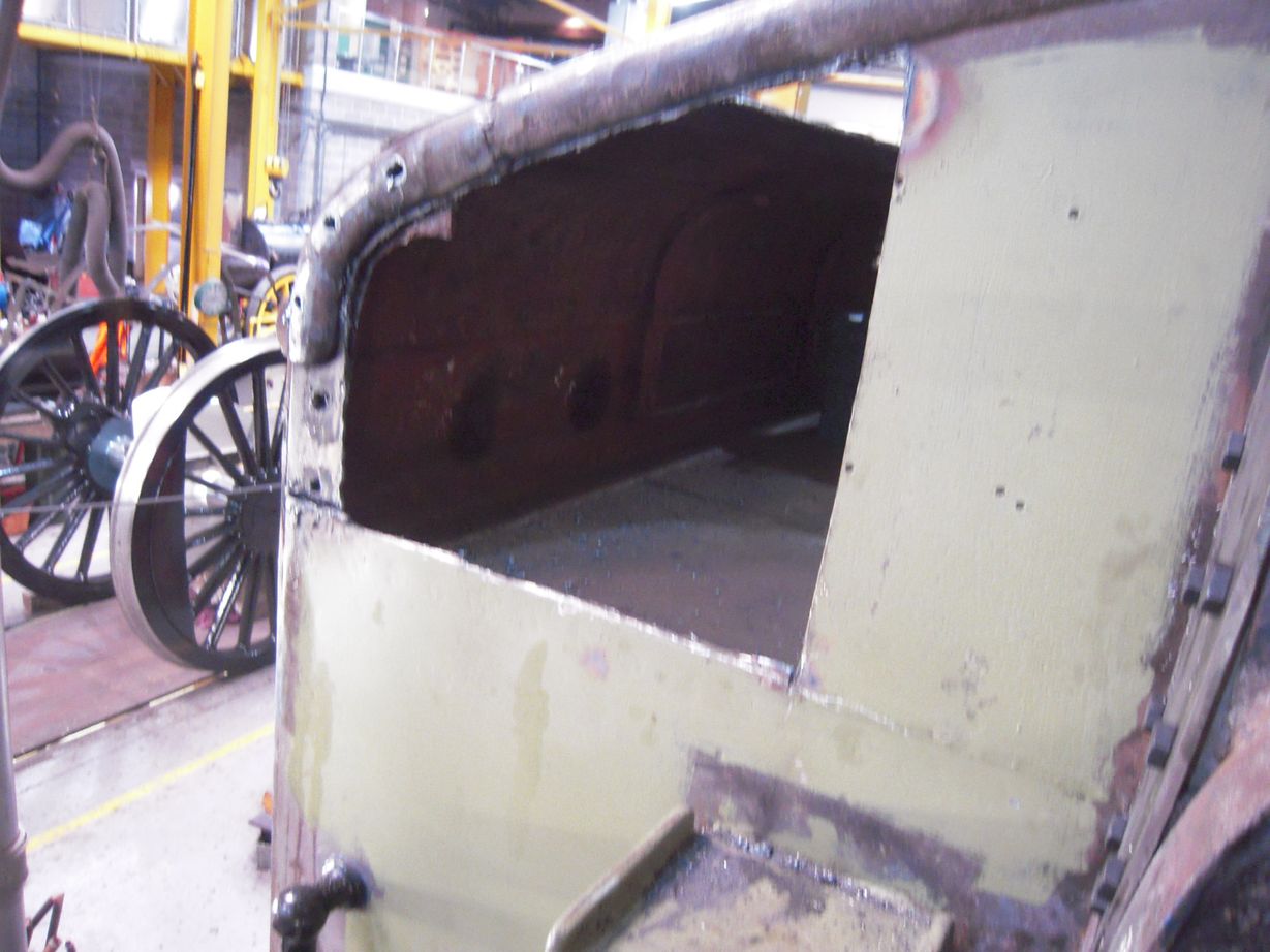
Work continues around the rear of the tender on the platework. The tender vestibule top arch has been fitted, not without a struggle. The arch piece was pulled down on to the vestibule top and was welded to its flanges. When trial fitted it was found difficult to refit. The arch with flanges wants to come straight down to slot in to the space between the vestibule end and the tender back. However there is beading along the top of the tender projecting in to the gap needed to lower the arch.
The cylinder relief valve overhaul continues with various gadgets being made to ensure accurate lapping of the sealing faces. Most have now been pressure tested successfully, but will require checking with a calibrated gauge to ensure they lift at the correct pressure.
The coupled axlebox oil trays have now been fitted to the leading and trailing axleboxes.
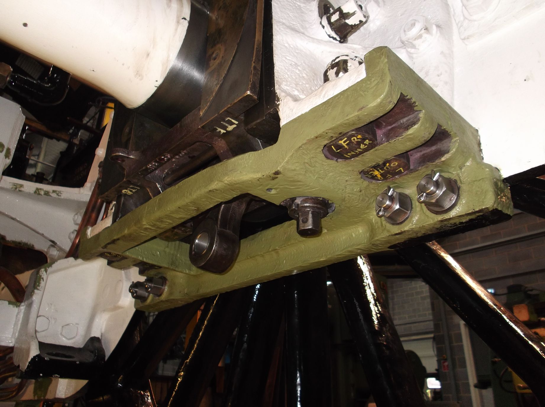
Meanwhile the springs were put up. One spring didn’t seem to hang right and was very high at one end. When examined it appears that the hole in the spring buckle is out of position, and this will have to be rectified. However it us some extra practice in handling the springs. One reassuring finding was that the repair to the leading right spring hanger bracket did not cause any additional difficulty in getting its spring in place.
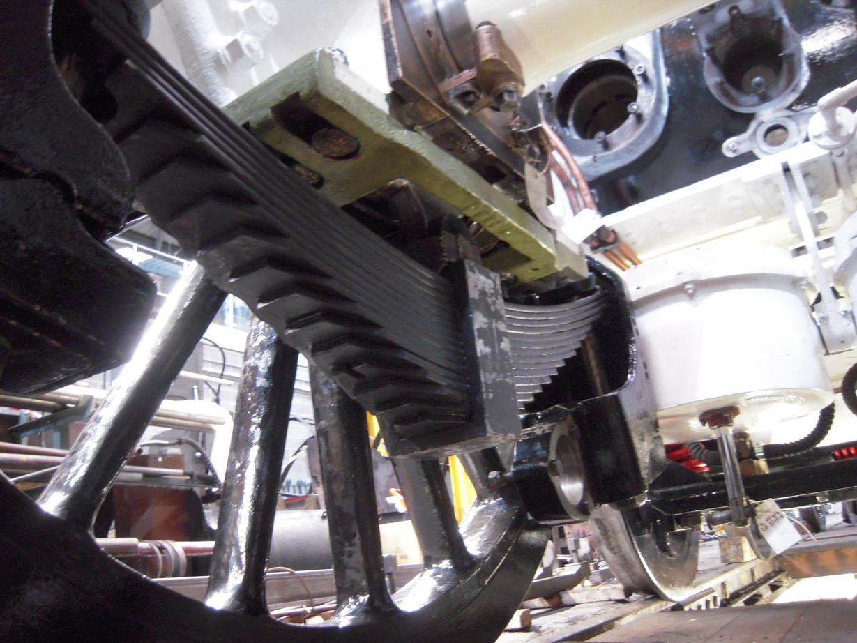
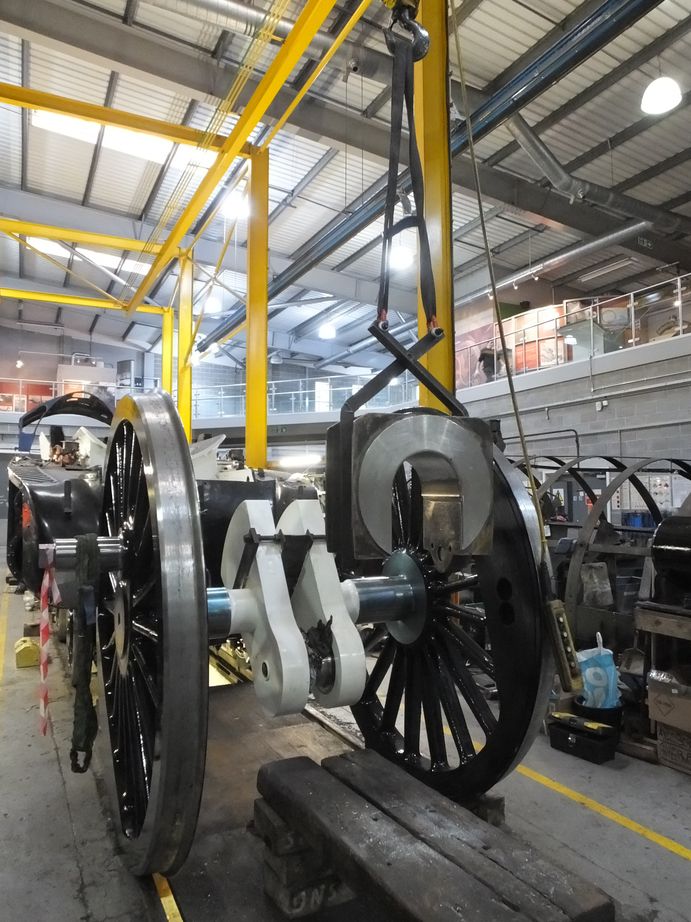
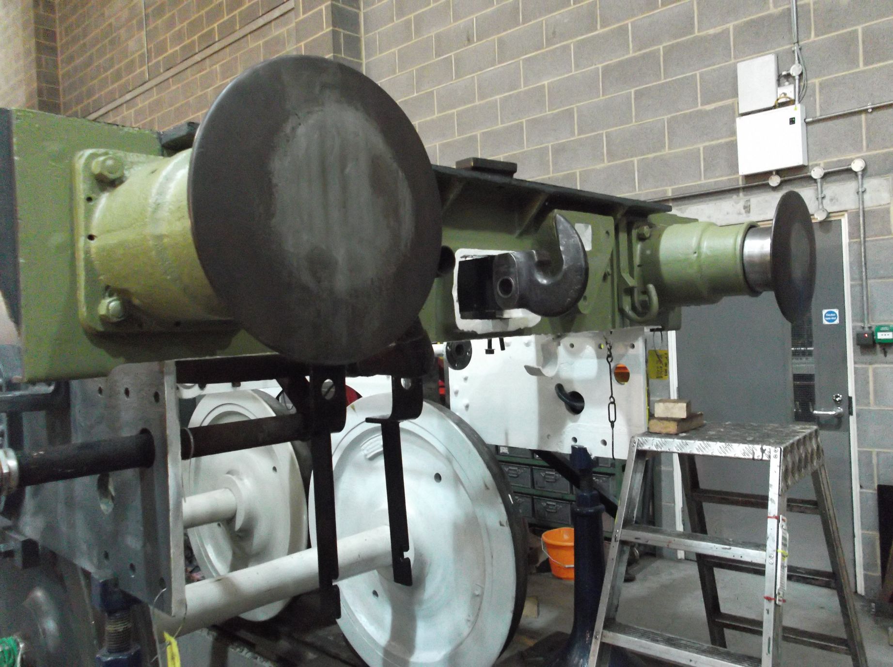
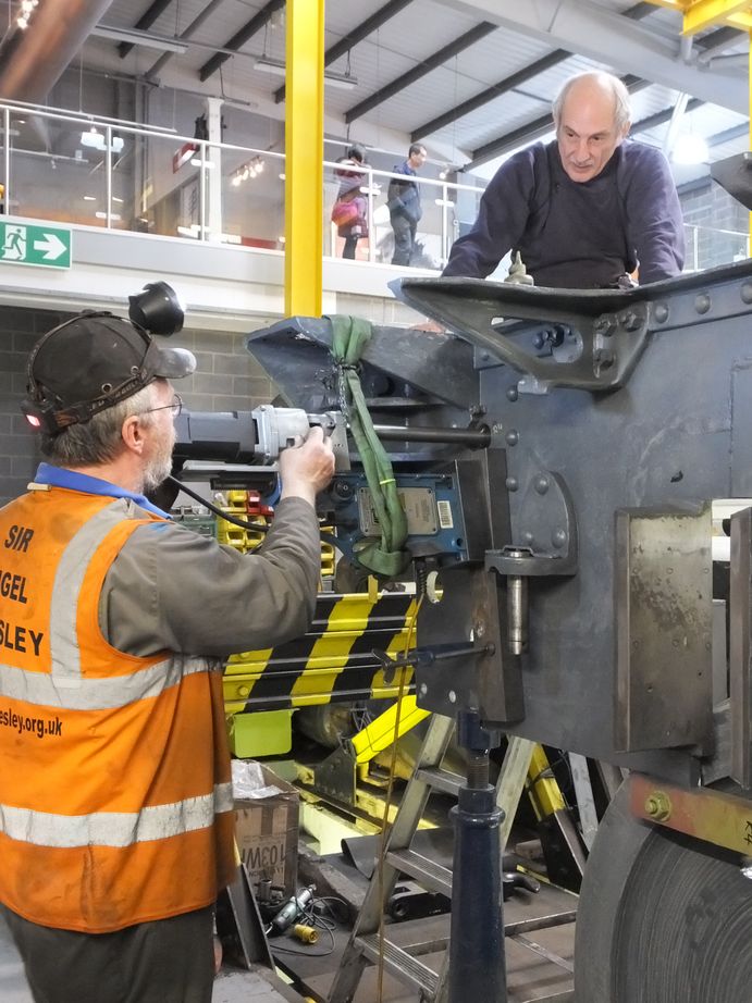
Other activities around the coupled wheelset include the adjustment of the wedges using long feelers to ensure the gaps are correct for the axleboxes. New cotters are now being fitted to lock the position of the wedge adjusters, meanwhile final torquing and pinning continues for the vertical hornstay bolts. The driving axleboxes are now scraped to their journals and attention has now turned to the refurbishment of the inside crankpin.
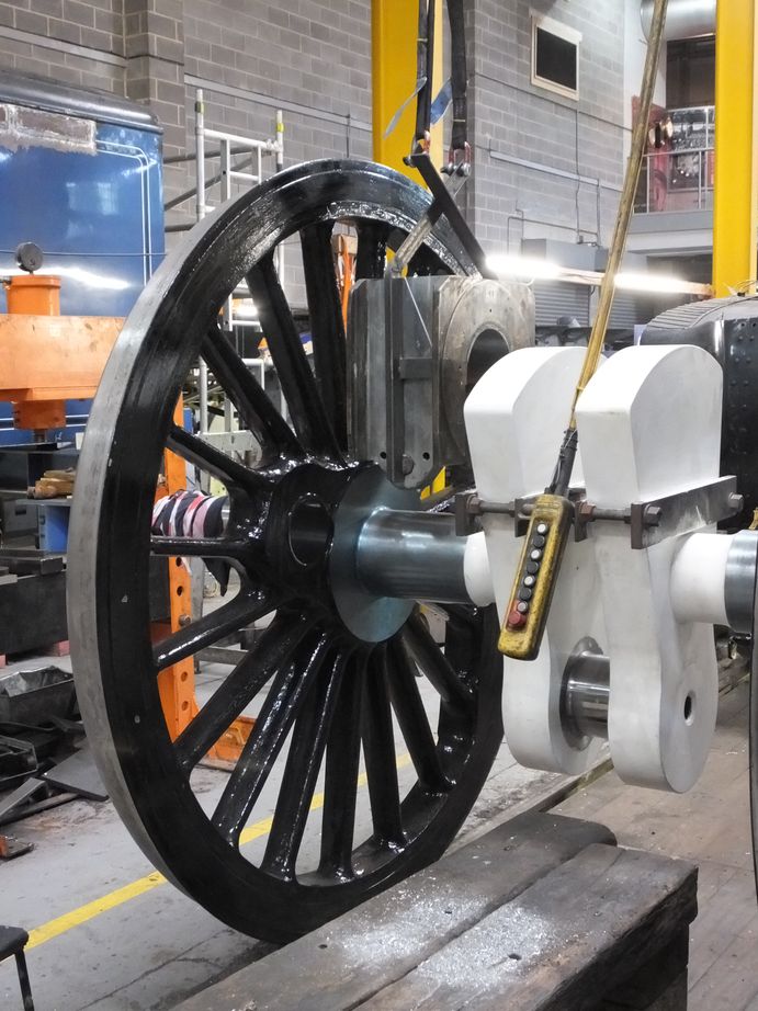
Work on specifying the coupling rod bushes is complete and component drawings have been produced. This has involved measuring the current worn positions of the driving crankpin face against the wheel and relating this to the leading and trailing crankpins to ensure we maintain the clearances required by the coupling rods. The holes in the rods have also been carefully measured. These aren’t plain bores but have tapered or stepped recesses to locate the bushes when pressed in. Correct location is required to ensure the right amount of the bush projects from each side of the rod.
The lower slidebar fitting is now on the final stretch with the shims specified and they now being made.
The installation of pipework continues. More work has been done on the tender and a lot of thought put in to how to improve pipe runs through the frames and to the tender top air tanks.
Meanwhile the pipework around the DV2 valve in the loco frames is complete and the mechanical lubrication runs to the front of the saddle is now progressing. As the upper slidebars are now fitted the lubrication runs to these has begun. The mechanical lubricator drive mechanism components have been examined and are now being refurbished.
This is the 38th update—you can read all the previous instalments here.
I’m looking for pictures of the 6 inspection or washout plugs on the rear side of the boiler just in front of the cab. I’v almost finished building a 5″ gauge Sir Nigel Gresley A4 but this detail I cannot find any clear pictures I can use to make the parts.
I live in Australia and can only go by pictures I can find.
Any help would be greatly appreciated.