Week commencing 3 December 2018
The new rivets for the tender spring hanger bracket have now been made. We have yet to obtain a suitably sized snap for these large rivets. The machining of the horizontal hornstay bolts continues and so does the sealing and testing of the cylinder drain cocks.
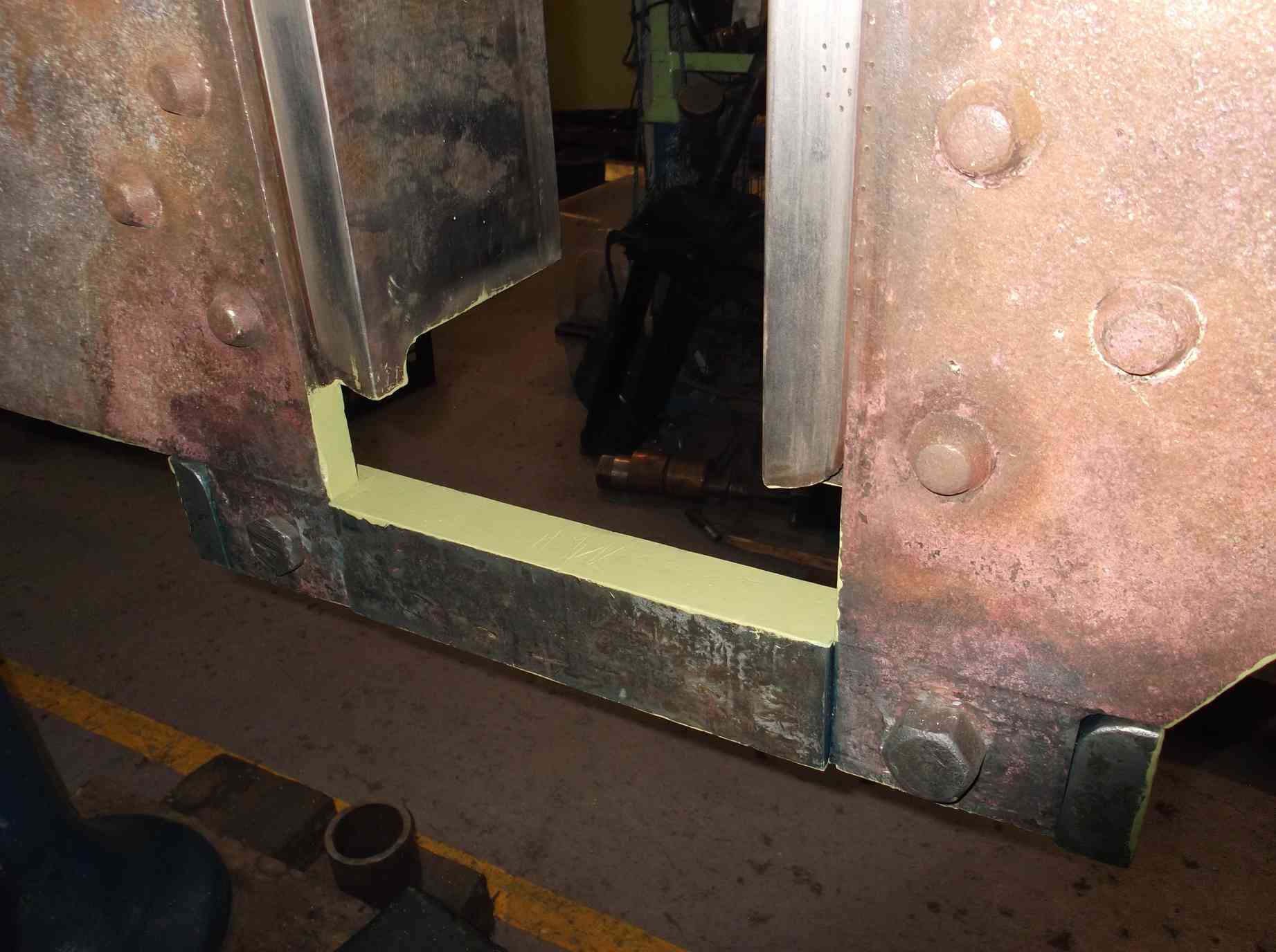
The refurbishment of the tender hornstays continues, with work progressing on the right frames. The right trailing frame has now been welded to restore the frame’s correct shape and the worn stays also require welding and finishing to suit.
Welding also continues on the front inside of the right hand frames to restore the plate thickness. This job progresses between the platework jobs our welder is helping out with around the tender tank.
The computation of the tender frame measurements has been carried out. We now have sufficient information to finalise the size of the bronze bearings. In discussion with our CME, it was decided to complete the work on the leading wheelset to confirm that the dimensions and methodology are correct and will work in practice. When this is done the remaining three wheelsets will be completed. Further dimensions are being taken of the tender horn gaps and the widths of the axleboxes to determine clearances.
The overhaul of the loco’s electrical systems continues with the ammeter and isolation switch assemblies refitted to the AWS battery box. Further work has been done on various other components and the loco’s left leading conduit run.
The last of the flexi pipes to the loco brake cylinders was fitted this week—to the large brake cylinder in the middle of the loco frames. All the clamps on the flexi pipes have been positioned to ensure they are in a safe orientation and won’t catch anybody working under the loco. The securing bolts for the large cylinder were removed to put a little more thread on them as they were washered out, so now only a single washer will be fitted. In addition, the bolts will be fitted with split pins against the nut for secondary locking, as per the LNER drawing.
The tender brake cylinder trunnion refurbishment is complete. The mating faces on the cylinder and covers have been cleaned and dressed ready for resealing. The flange faces on the cylinders and the mating pressure connection flange have also been prepared and new seals cut.
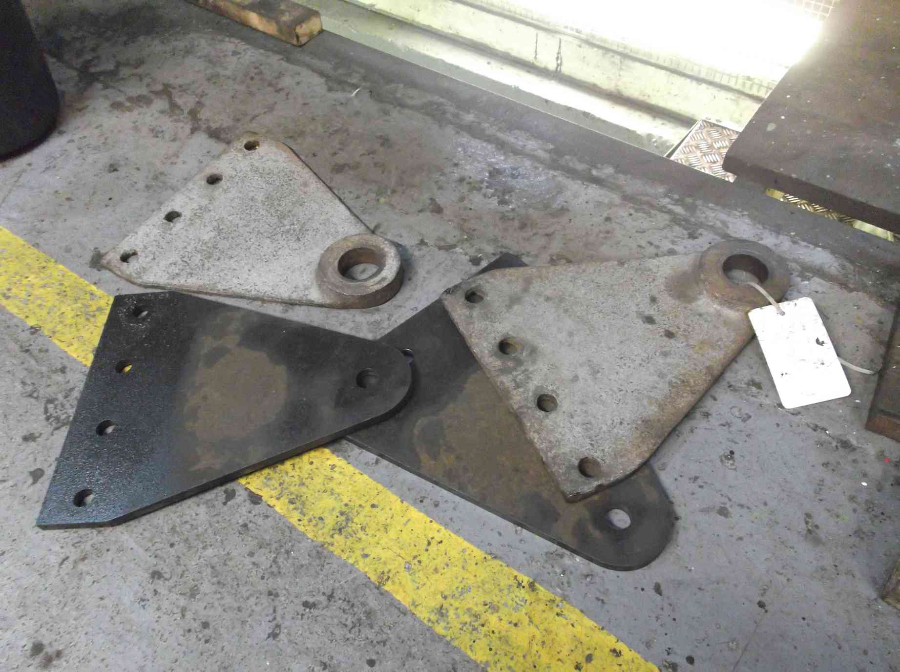
The tender brake cylinder end brackets are to be replaced. The plate has now arrived at York has been drilled with the mounting holes and a pilot hole for the cylinder trunnions, which will be bored out to finished size.
The water filler space on the tender top has seen a lot of work in descaling and getting down to sound metal. This has been a long and noisy job. Almost daily there have been reports of new holes being created by scale or filler coming away under the needle gun. This week staging was put up at the rear of the tender so that we could get closer to the outside top. Paint along the outside is now being stripped back to expose the area at the water filler space floor level where holes are coming through. This is quite a complex area as the top of the corridor connection is here. A scheme is now being worked out for the repair work.
Work also continues at the bottom of the corridor connection, with the concrete removed to expose the plate beneath. This area is being worked on to find sound material to which new plate will be welded.
The adjustment of the middle slidebar shims is now complete, with the slidebar being within 0.001 inches parallel to the cylinder centre. Attention is now turning to the outside slidebars, which we predict will be easier as the initial fit is better. The measurements are taken from a taut piano wire.
I was asked recently what we use piano wire for on the engine. I then realised that many of our readers probably have not come across this before. So by way of explanation, we use the wire for projecting the centre line of the cylinders along the loco. We then measure from the wire to various critical locations on the loco. For example, the cylinder centre passes through the centre of the driving axle—it has to, to ensure even stroke of the piston and minimise side thrusts. So we have to make sure that when we set up the bearings, slidebars etc, that all centres are where they should be. We do this by measuring to the piano wire.
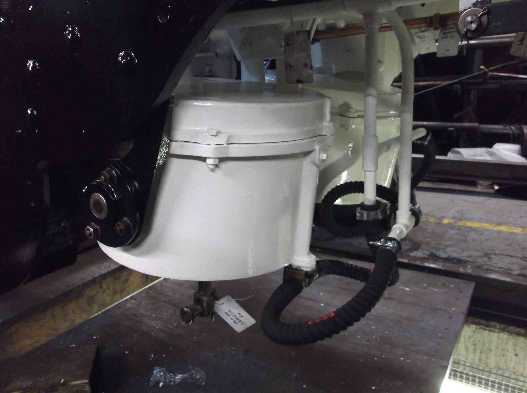
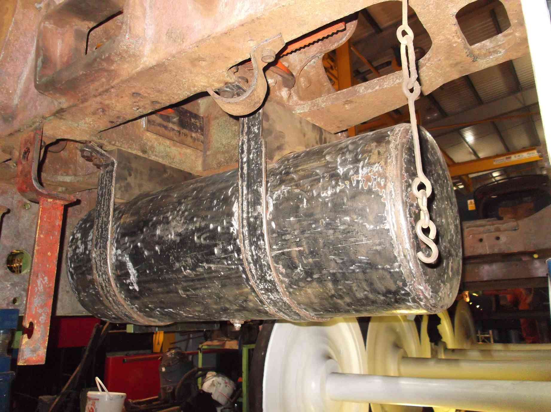
The tender vacuum brake train pipe was refitted to the tender frames this week and to allow positioning of other pipework the vacuum reservoir tank was refitted. The tank was cleaned up and prepped for painting and then refitted. The tank will be pressure tested as soon as we sort out a fitting that matches the unusual one the tank is fitted with. The tank is held up on straps. The straps require refurbishment and brackets on the dragbox are life expired and require renewal.
Scraping of the coupled axleboxes continued this week, when time allows. Last week Llangollen got in the way and this week the RSSB Mainline Heritage Roadshow took me away for the day. The right trailing is now effectively completed. Unfortunately the left trailing had a minor defect in the metal of the crown. It appeared to be shallow so I had hoped that scraping would remove or minimise it to acceptable levels, but it persisted so will require remedial work. Another box, the left driving, will also require rework after the discovery of the earlier defect. Both axleboxes are now at contractors for rectification.
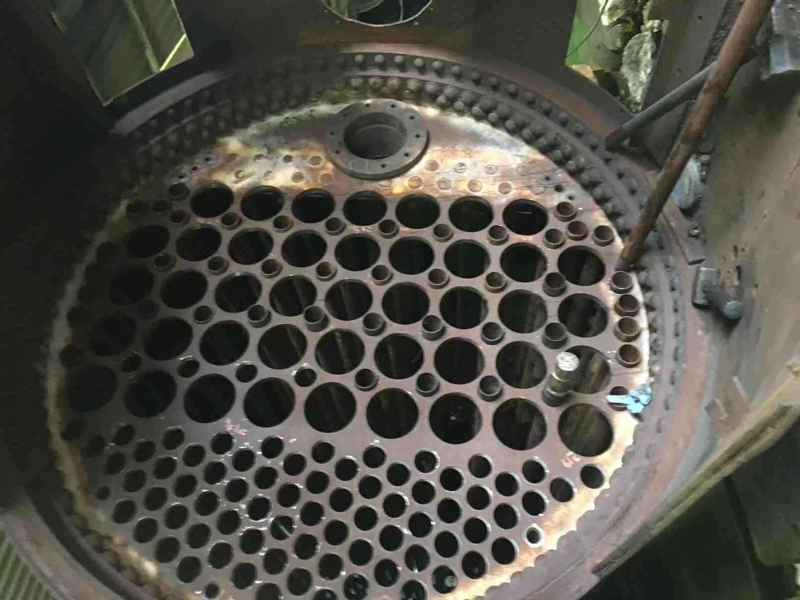
Now that the pre-tubing boiler inspections has been carried out, tubing has begun with the fitting of the small tubes around the flue tubes. Work also proceeds on fitting and finishing the crown stays.
Weeks commencing 10 and 17 December 2018
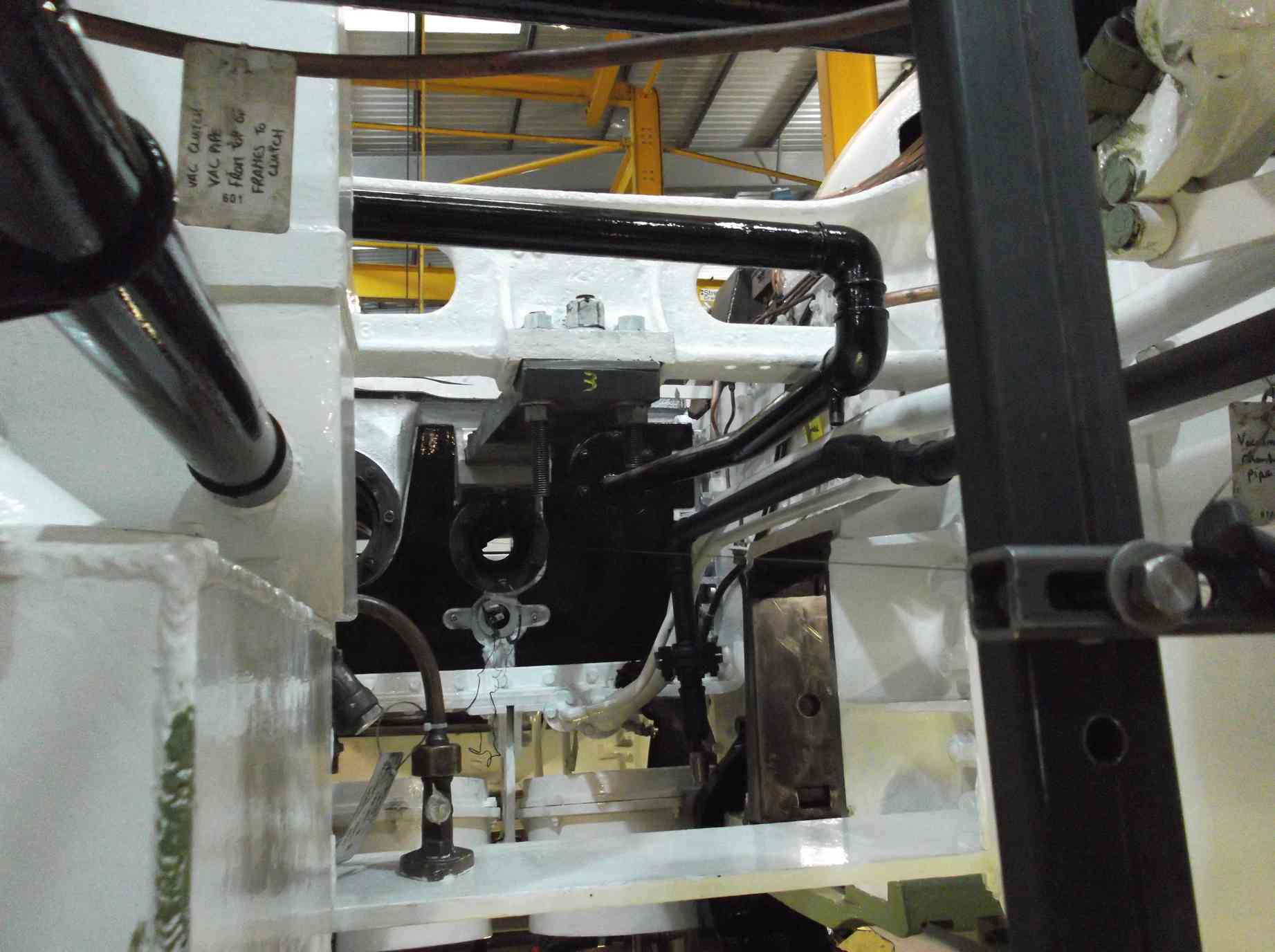
The new pipe flanges have been machined for the steam supply run from the manifold in the cab to the air pump governor. The pipe fitting team has wasted no time in attaching pipework and staring to route the pipe from the governor. Work continues both on the loco and on the tender pipe systems. The air brake hose connection flanges for the tender rear were stripped and cleaned up and fitted enabling an end point to be determined for the new air brake runs to the tender rear. To allow a better idea of the space available at the front of the tender frames the water valves, pipes and brackets were recovered from store and are now being refurbished before fitting.
The tender vacuum reservoir cylinder put in position to allow new pipe runs to be planned, is held up on a ratchet strap as the brackets and steel mounting straps need repair work. A new bracket was manufactured and is now fitted to the trailing dragbox. Material has now been purchased to make up new ends for the mounting straps. The remaining di-pen NDT on the trailing dragbox and brake hanger brackets has been completed, this completes the examination of the tender frames.
The tender vestibule end has received exploration over the last couple of weeks with needle-gunning removing most of the steel in this area. The plate over the top of the vestibule including the handrail has now been removed. Internal brackets and rivets have also been removed. The top vestibule support brackets have also had to be removed. The new front floor plate is now welded in position. Further welding will have to be done to finish the fitting of this plate but it’s looking really good. Some new plate has been purchased for the vestibule being bent up by our supplier on Teesside to our templates produced.
The boiler maker team finished the frame top angles on the tender frames. I ran a straight edge across them and the leading dragbox and alignment is very good. The welds in the angles have been dressed to make it look like the original fitting.
The right driving axlebox that was at contractors for repair has now had the detached area of whitemetal replaced and the hornface skimmed. As soon as the box was finished it was collected by one of the volunteer Engineering Team who had a very early trip to Darlington to collect the box, bring it to York and then do a day’s work on the tender.
The rear tender footsteps are all now to undercoat. They will not receive further paint until fitting to the frames. The buckeye coupling has been re-bushed by, and the lock built up with weld as permitted by the BR refurbishment procedure. The lock will be filed and the buckeye closing dimension adjusted.
The tender brake cylinder connection flanges have now been fitted to the cylinders. The orientation has been checked to ensure train pipe and reservoir are correctly positioned. The tender rubbing block has been cleaned and received descaling and is now in undercoat and ready to refit. It has been measured so that new bolting can be organised.
The tender hornstays on the right frames are being repaired and fitted. Progress is slow but a fine job is being done to the heavy wear evident on the frames and hornstays.
The machining of the loco horizontal hornstay bolts is well advanced with the leading wheelset eight completed and ready for fitting. With the day that the wheels will be in approaching, work has started on the brake gear with the return to the workshop of the first loco brake pull rods. These are being stripped prior to NDT.
Work continues on the slidebars. Now the middle is completed attention has turned to the right-hand. The wire has been put up and the front alignment set. Unfortunately quiet is needed to do the job accurately using the audible detection measurement method we use and it’s been a little noisy in the workshop lately.
Work continues on sealing and pressure-testing the drain cocks. A further two valves being completed. Two valves were found to leak from the casting bodies when under pressure. The areas of the leaks were drilled out and silver soldered, unfortunately this was not entirely successful, though it did reduce the leaks considerably. Further soldering will be required.
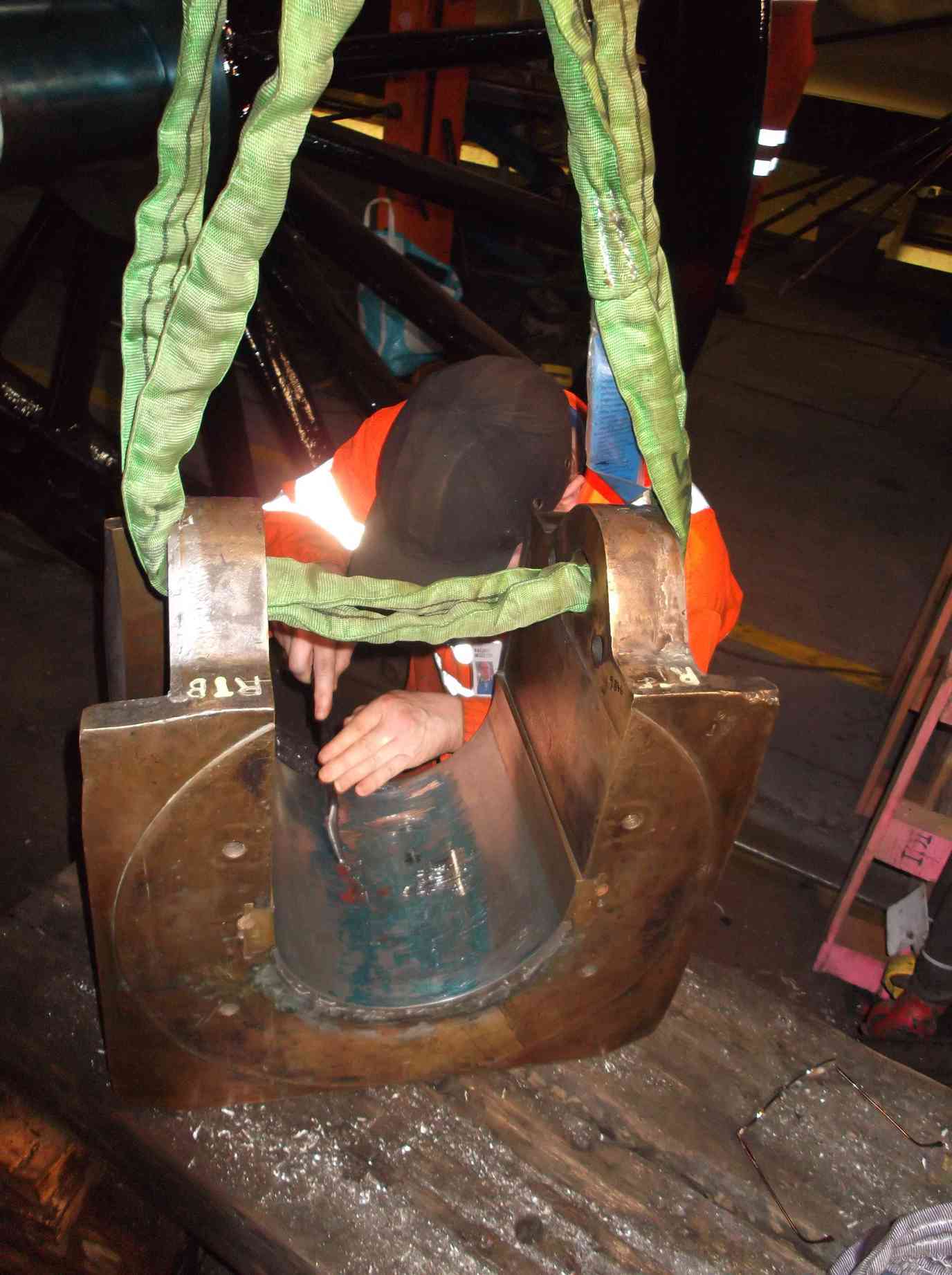
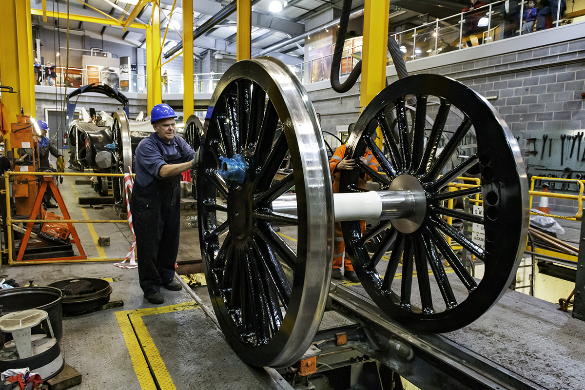
Both leading axleboxes have now been scraped to their journals. Repeated trial fitting on blued journals requires two, one to operate the crane and one to carefully land the bearing in position on the journal. Then both to rock the axlebox. A time-consuming job though made much easier by the availability of the overhead crane. The completion of the leading axle has allowed the fitting of the wheelset and the bogie.
The adjusting wedges on the loco horns has exposed some sharp edges which could possibly score the flange on the loco axleboxes, the leading set have now been carefully dressed.
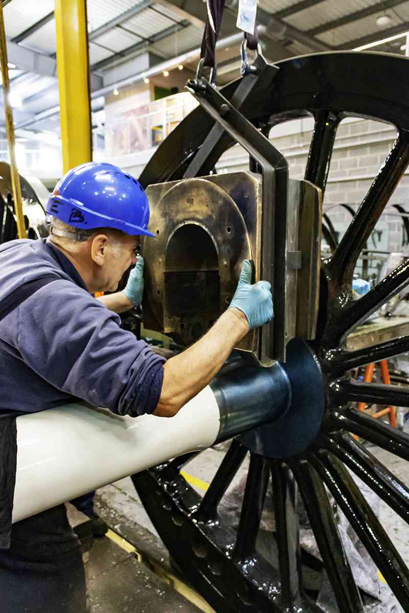
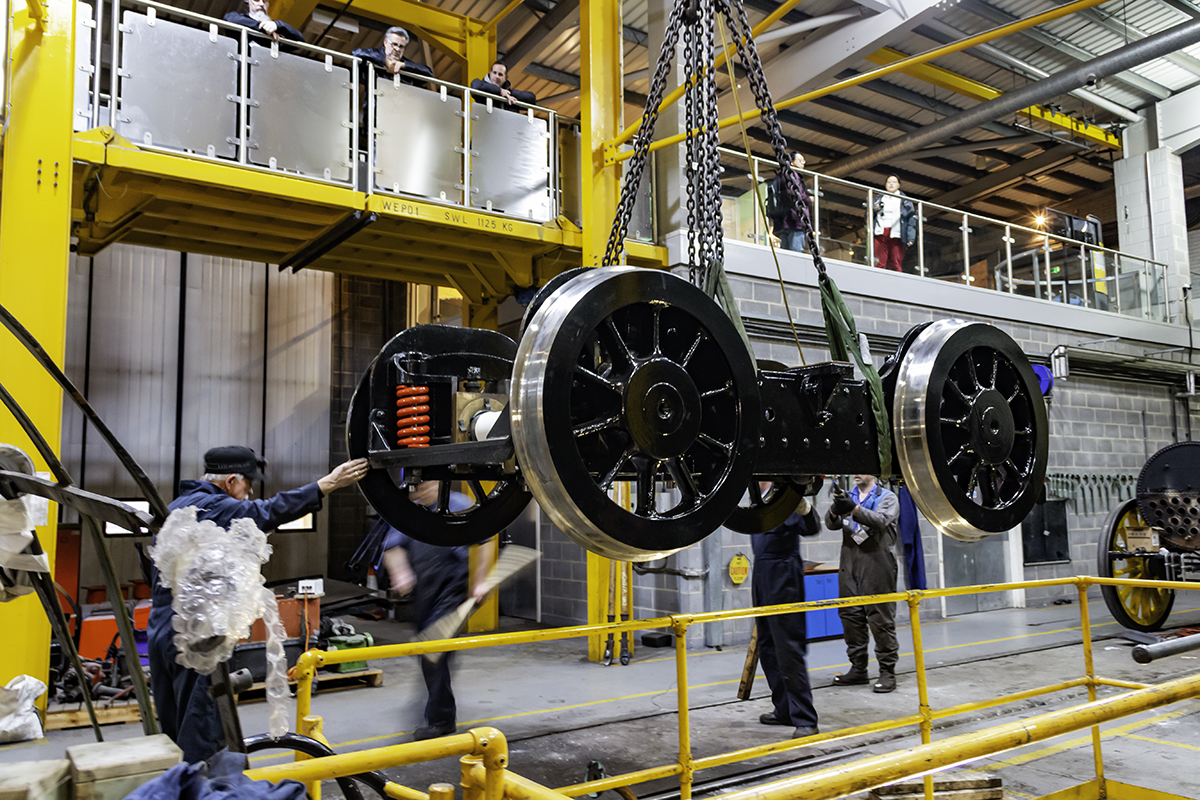
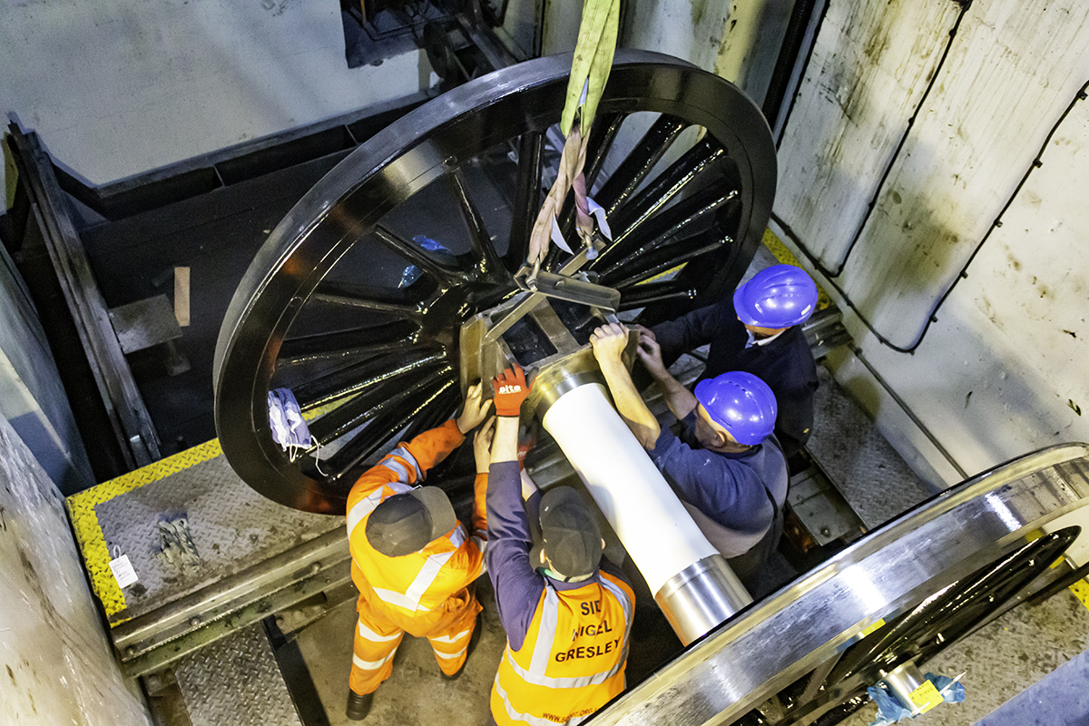
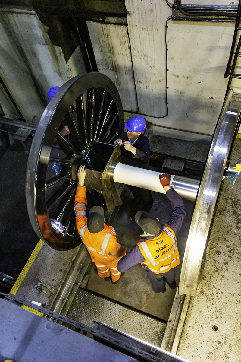
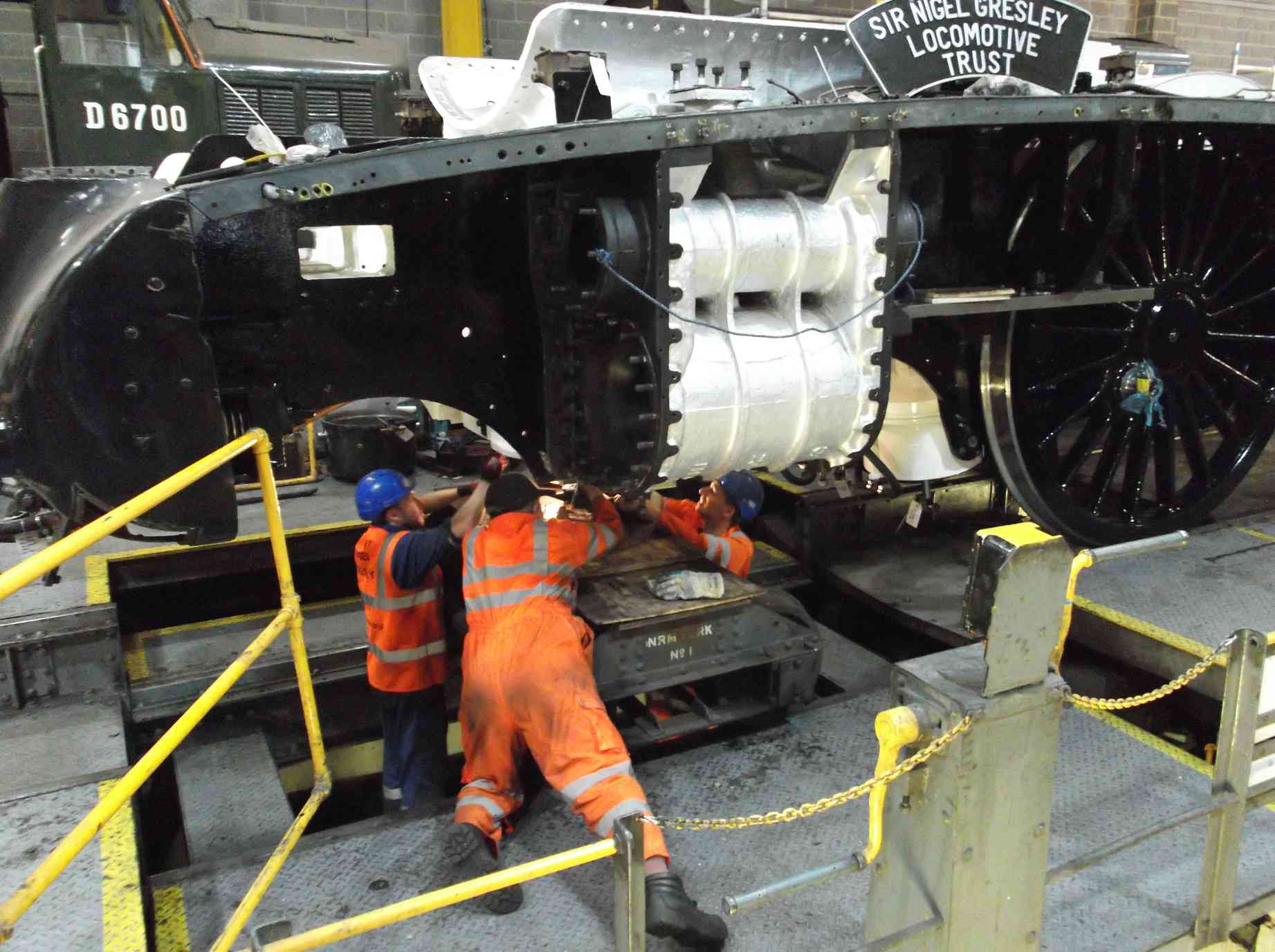
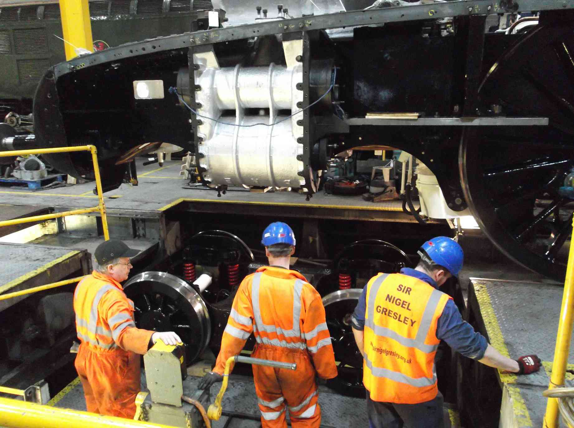
The leading wheelset was fitted on the NRM workshop wheeldrop. The loco was pinched forward so that the accommodation bogie was positioned on the far side of the wheeldrop. Prior to moving the loco the leading wheelset and bogie were placed on the south road in the workshop, being lifted there on the wheeldrop crane, the spectacle being appreciated by the public on the viewing gallery.
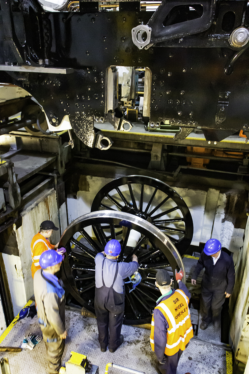
The leading wheelset was then lifted by crane in to the wheeldrop pit and placed on the lifting platform. While at the bottom of the pit the axleboxes were assembled on the journals complete with underkeeps and spring hanger brackets. The hornstays on the frames were previously removed in preparation. The lifting platform was then moved to under the loco and raised. With someone watching the entry of the axleboxes each side in to the horns, the platform was raised in small steps, and a little adjustment to the position of the wheelset made. The axleboxes entered easily and the clearances looked good. These will be confirmed by checking with feelers later.
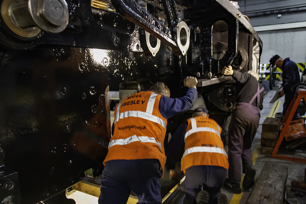
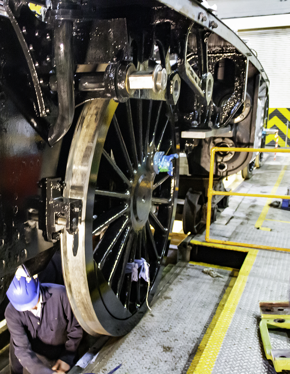
With the axleboxes in position the hornstays, which are remarkably large and heavy once they have to be manually lifted and held in place, were drawn up on to the hornblocks by lengths of studding. The studding was made up for this job and will form a kit for doing this job in future. With the hornstays nearly up they were drawn in to their final position by horizontal and vertical bolting. Once started, with the hornstays off the frames, the job has to be finished, so thanks to the team who stayed back until completion.
With the leading wheelset in the axleboxes, they were packed against the frames and the loco was moved back to get the accommodation bogie over the centre of the wheeldrop. Thanks to the team who came in, without which we would have struggled to complete the job or even move the loco.
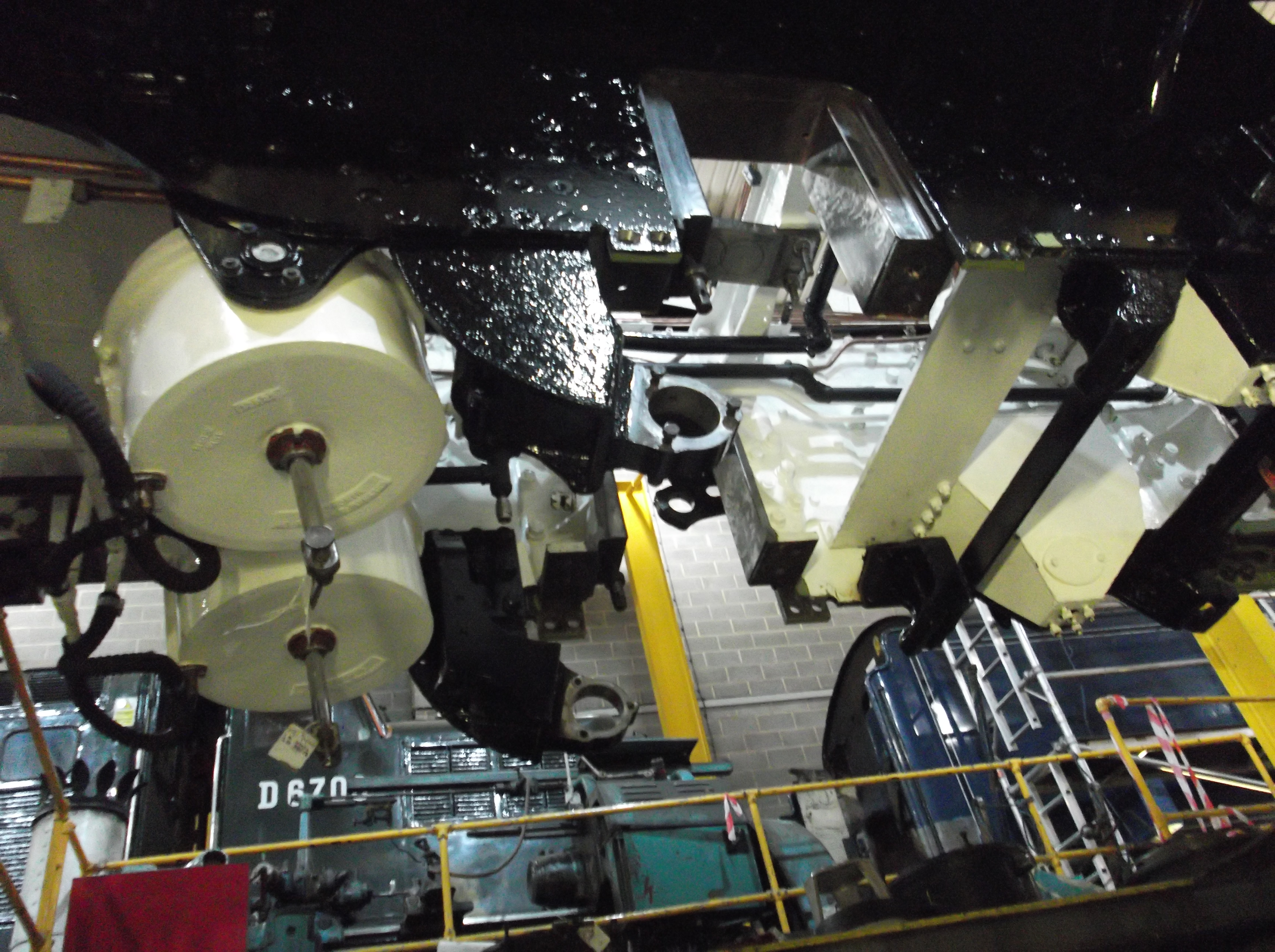
This time the bogie was lifted off the south road with the crane and lowered in to the pit. This was a close fit and had to be pushed with timber lengths to clear a modern cable tray on the wall of the pit. At the bottom of the pit, ropes securing the rubbing plates on the top centre of the bogie were removed. The bogie was then lifted under the loco. There’s a lot more to watch with the bogie going up so with people all round we slowly brought the bogie up. It was clear we would be close to the vacuum cylinder flexible pipes. This was expected as it was the case with the last installation. When close to fully up the pipe routing was discussed by our CME and pipe ftting team leader and they decided it could be improved, so the pipes were removed.
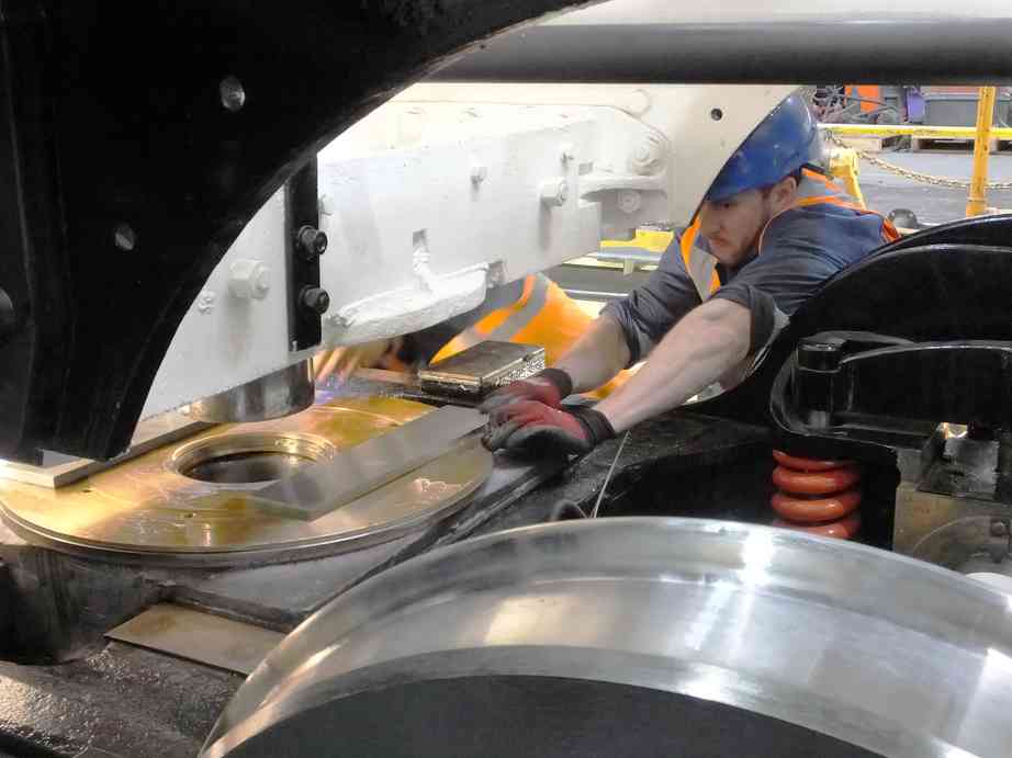
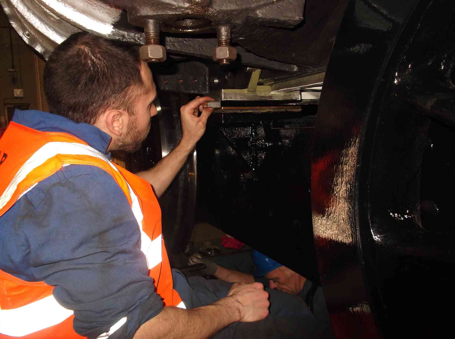
Raising the bogie continued on to the centre bearing of the bogie but it was apparent that we would not be able to measure the side bearer gaps as the loco frames and bogie would not be evenly loaded before contact on the right side bearer. So the bogie was lowered and pieces of gauge plate put on the bogie centre to give us a known stand off. With the weight of the front of the frames on the bogie the side bearer gap was measured. While this was being done the bogie spring hanger nuts were removed, greased and set to give equal compression to the bogie springs.
With the measurements taken, the bogie was lowered once again, the gauge plate was removed and the sidebearers removed. They will be skimmed to give the correct clearances and to ensure they are level to the bogie. Meanwhile, screw jacks were set up at the centre of the frames to support them over the Christmas break as at the moment the frames are only supported at the bogie and Cartazzi.
This is the 35th update—you can read all the previous instalments here.