Weeks commencing 5 and 12 November 2018
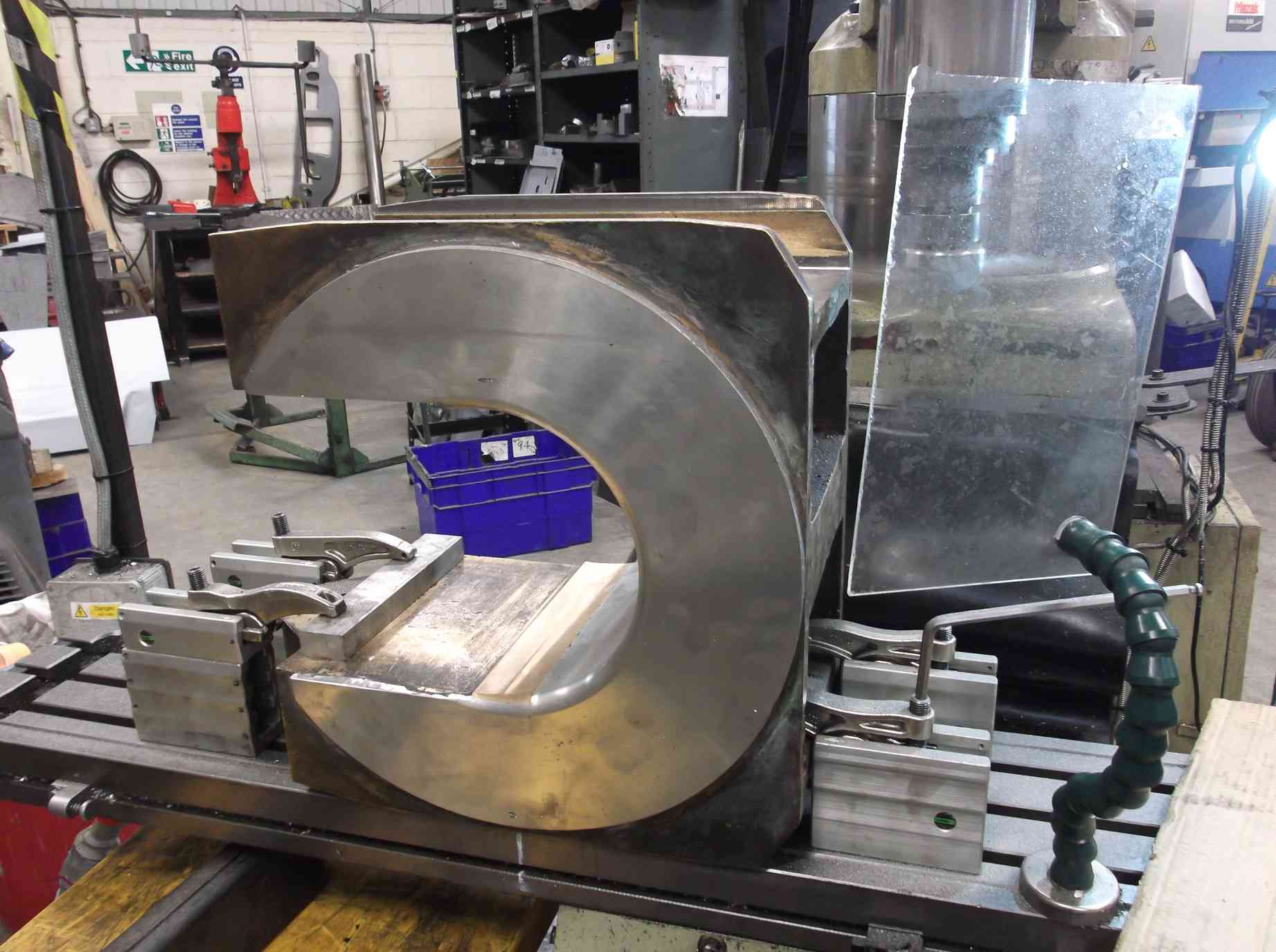
The axleboxes were taken to contractors to have the horn faces machined. The transport was supplied free of charge by one of our Engineering Team volunteers, saving considerable trouble and expense in moving these heavy items. The first axlebox was soon put on the machine and I witnessed the first two off. Five of the six were soon completed but while machining the right driver a section of whitemetal detached, so this will have to be re-metalled.
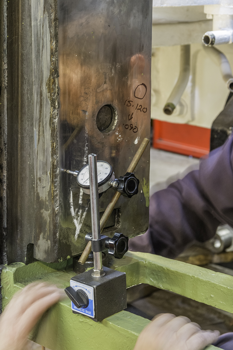
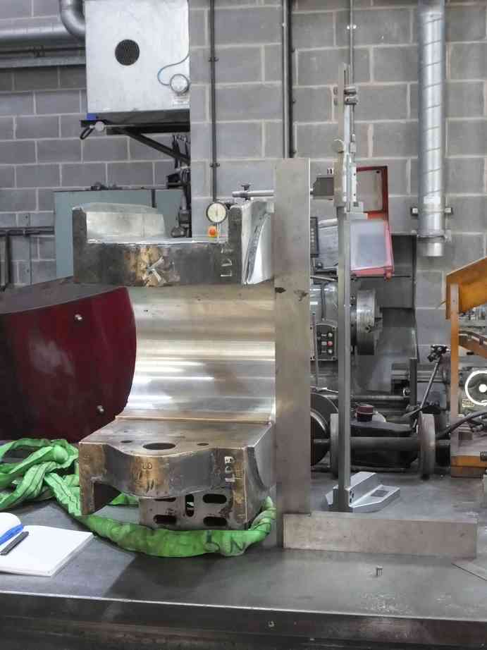
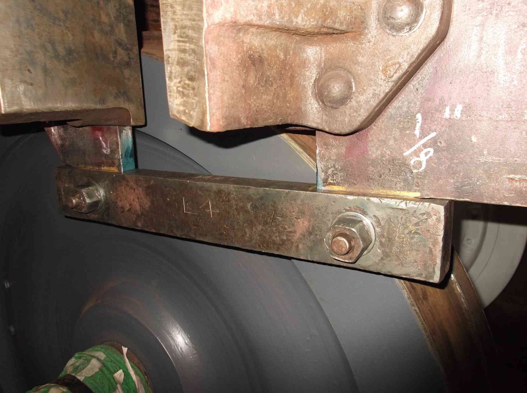
The five completed boxes were collected, again by an Engineering Team volunteer and delivered to York. At York they were put up on the surface table and the distances over the horns carefully measured. When the dimensions were digested the adjustable horn wedge on the locomotive was adjusted to give the correct clearances for the axlebox. The clearances will be checked when the axleboxes are in place.
The adjustable wedges are thought to have not been moved in decades so we were pleasantly surprised how easily this work progressed. There is still some work in dressing the sides of the wedges where edges have projected over the fixed part of the horn and this is sharp to the touch.
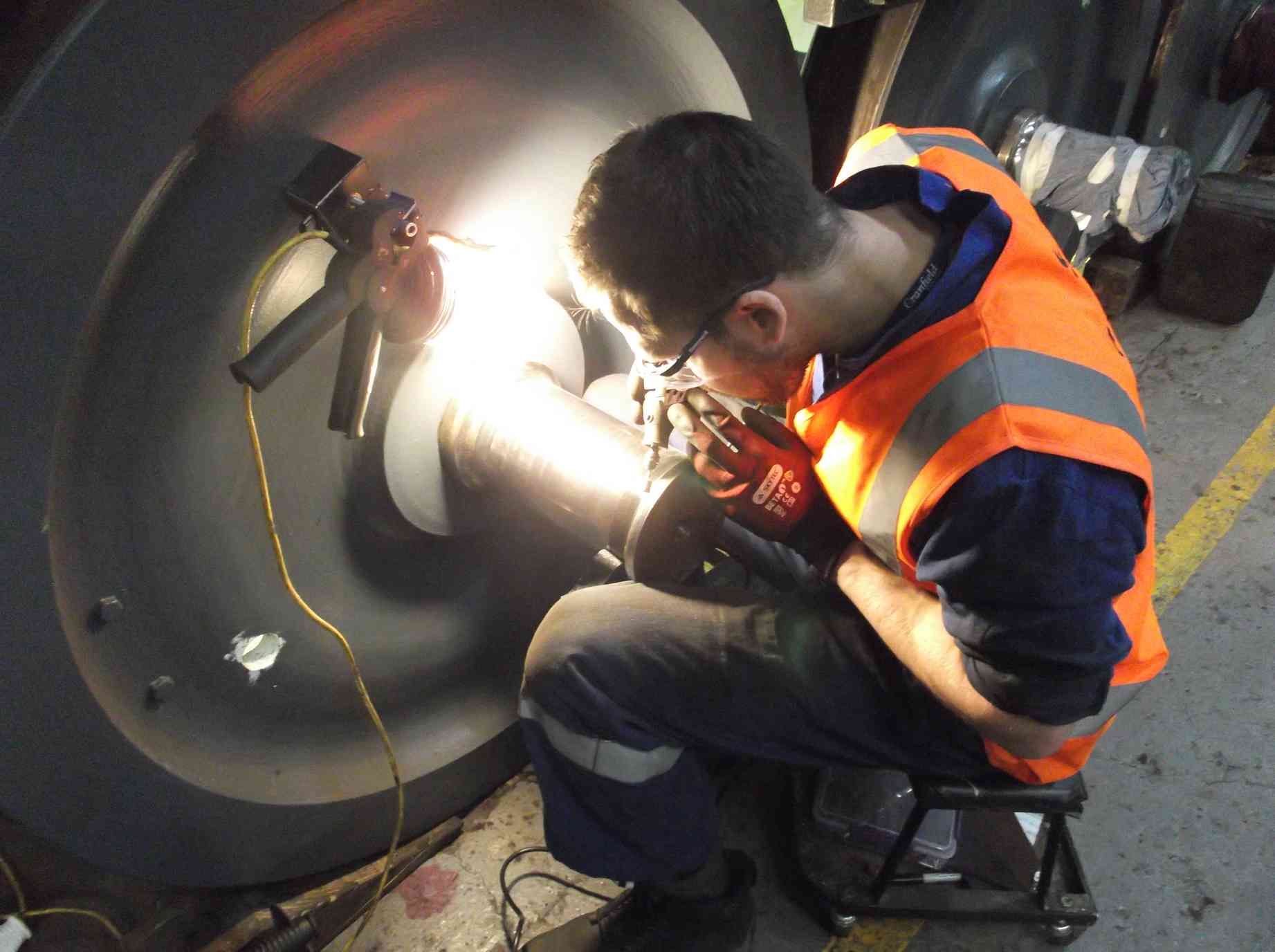
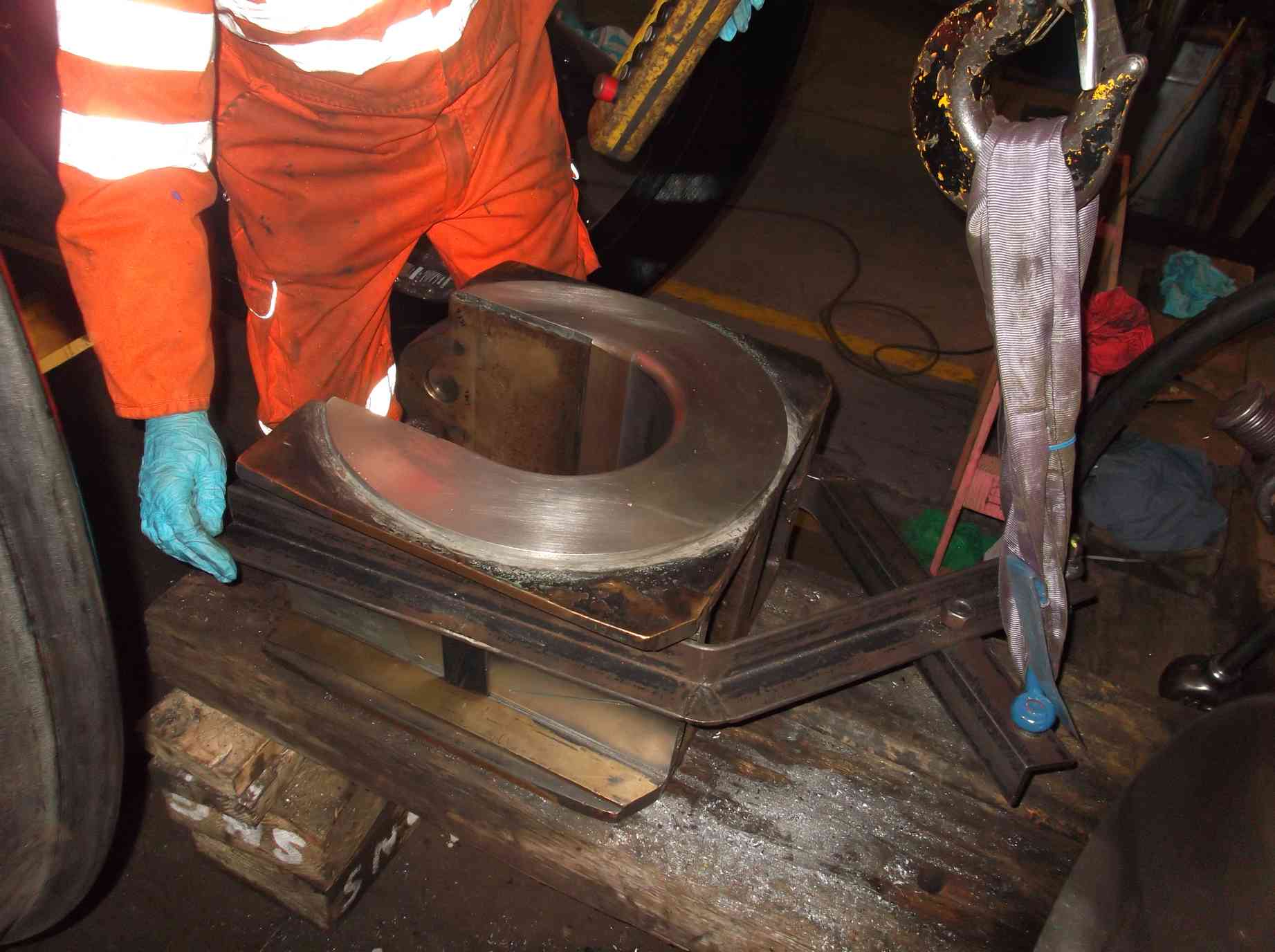
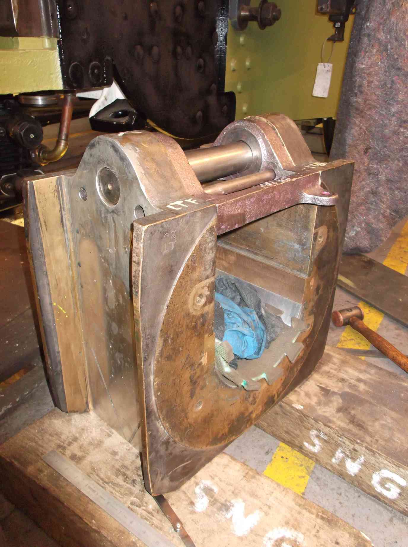
The first axlebox is now being accurately fitted on to its journal. The same procedure is being carried out as when the bogie boxes were so treated, however the coupled axleboxes are much larger and take much more time. However we were very pleased with the initial fit of the axlebox so the Grosmont machining of the axlebox is good and having the journals trued when at the SDR will save a lot of time.
While the axleboxes are being fitted to the journals the ones waiting their turn are having their underkeep brackets fitted. When happy with how the brackets fit, the spring hanger pin and smaller side pins are checked for fit, and to ensure they do not project past the axlebox horns where they could foul the horn faces on the loco.
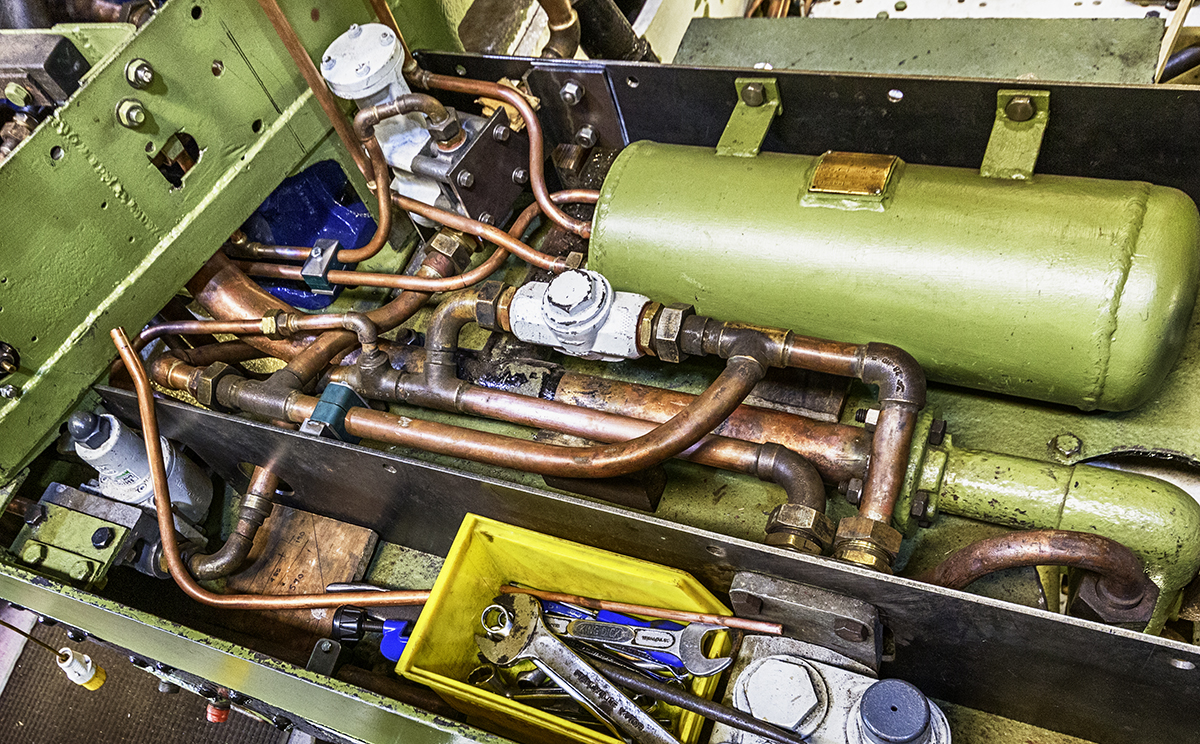
Work continues on the piping systems on the loco. A plan has been worked out for the air pump governor position and the routing of the governor outlet to the air pump. New pipe and fittings continue to be purchased and collected from suppliers, all masterminded by our volunteer pipe fitting team leader.
While working on the air system piping, work also continues on the new steam heat pipe installation on the tender. The rerouting of the air brake piping on the tender has had implications for the existing vacuum reservoir pipe run so this will be rerouted. This pipe has now been removed. Some will have to be replaced as when descaled it is now clearly life-expired. This has turned in to probably the most labour-intensive and complex part of the overhaul.
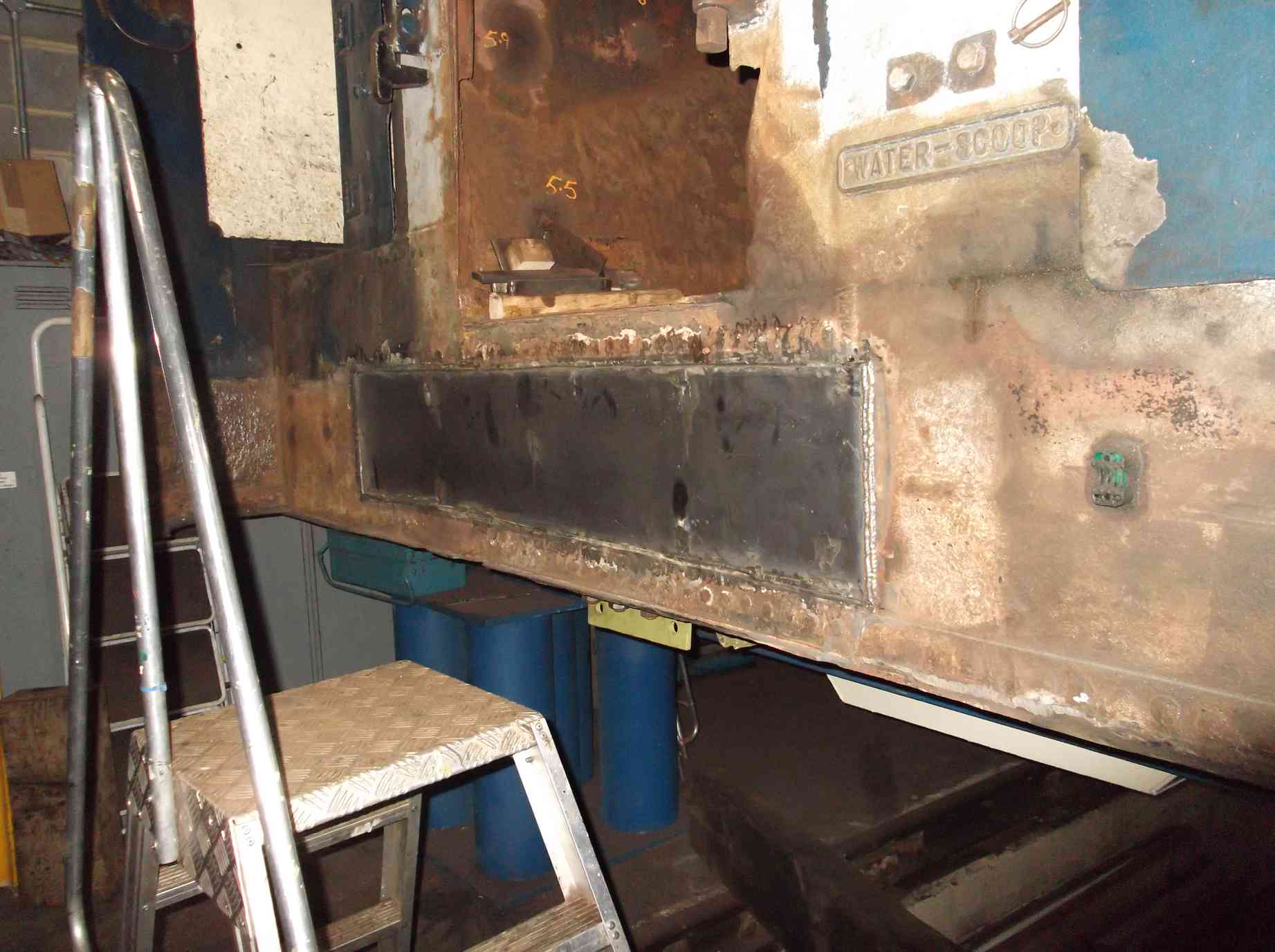
The tender tank refurbishment continues. The new bottom plate which was bolted to the lower side of the tender has now been drilled through. The new plate was removed then the old plate cut out. There is now a big hole at the front of the tender. The new plate for just inside the front of the tender tank to cover the thinned and holed plate was cut to size and the dressing of the existing plate and structure completed. The new plate was fitted and then welded in.
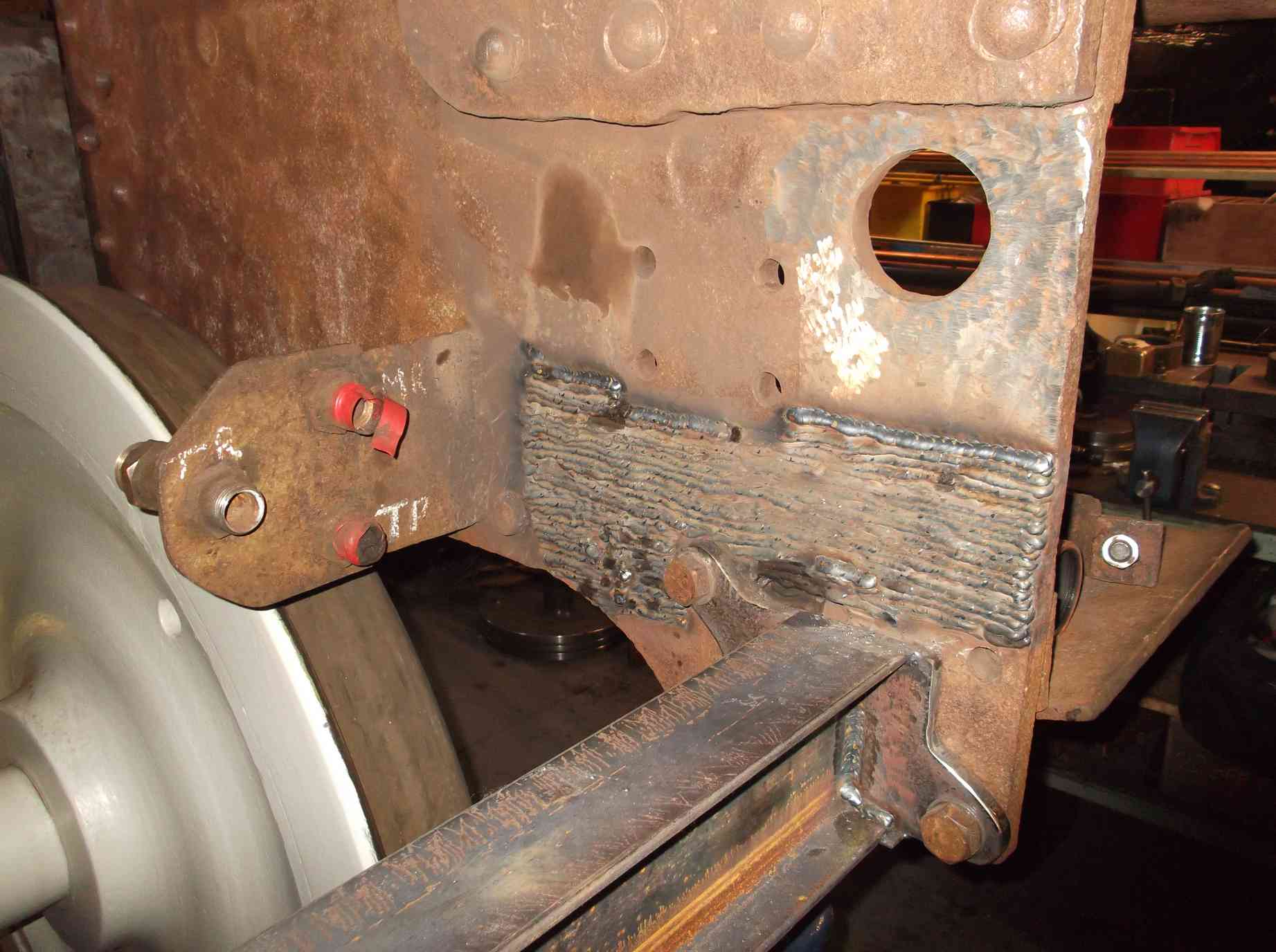
The front of the tender frames where it is badly wasted is being welded up a little at a time to minimise distortion of the frames, in between welding up the AWS battery box, various brackets and sundry other items. Our welder must be very busy as we keep running out of welding gas and MIG wire.
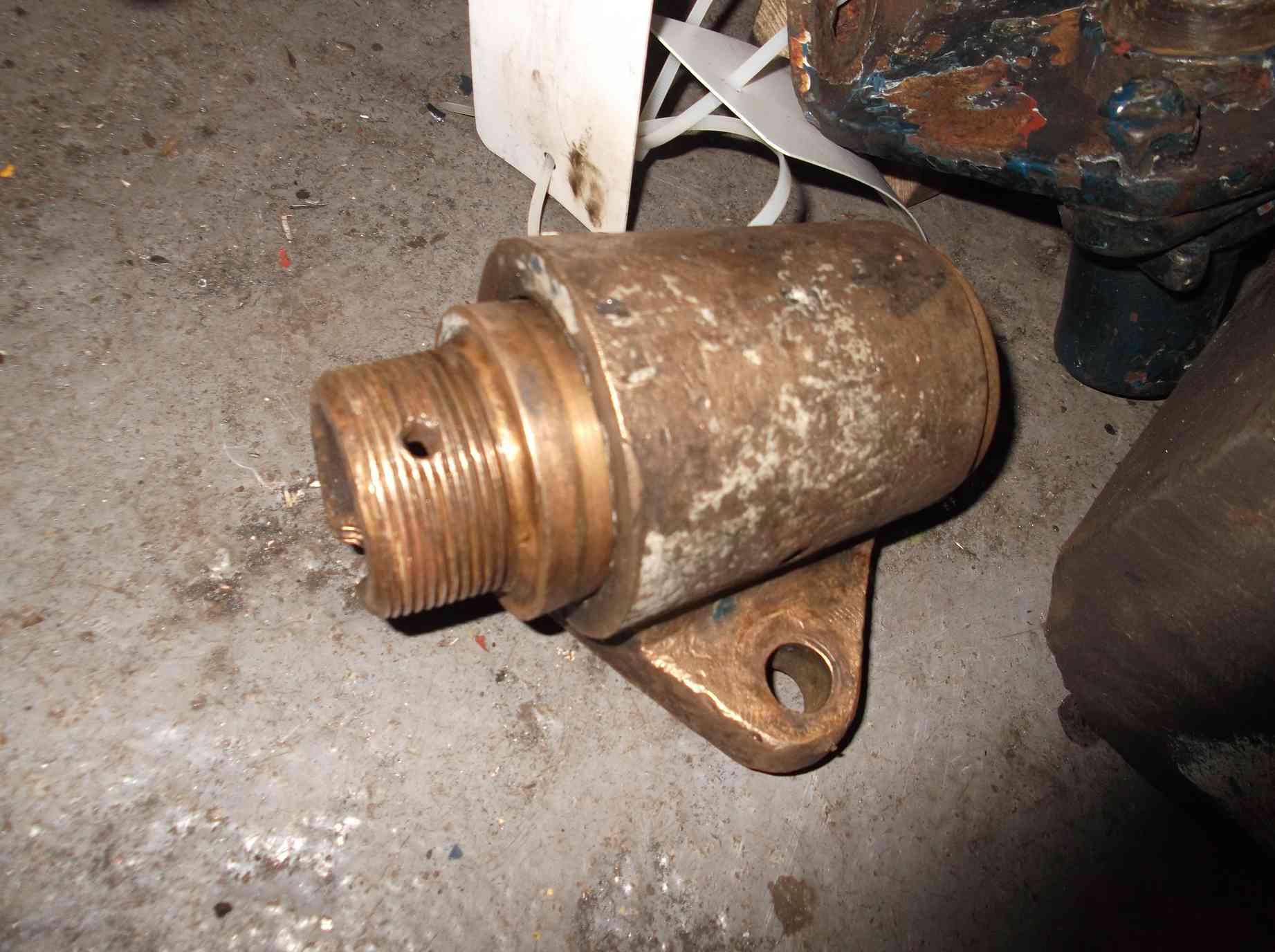
The water level indicator from the front of the tender tank was dismantled. The bronze valve at the bottom was removed and cleaned and the steel tube that makes up the main body of the indicator cleaned. The tube appears to be very old though the bottom end has been renewed at some time, however the bottom that the valve screws in to is corroded to such an extent that there are no threads remaining in it.#

The refurbishment of the tender hornstays is continuing well, and quicker than I had originally thought thanks to the time put in on this job by one of our volunteer fitters. The left side is now approaching completion. The hornstay refurb has involved dressing the damage on the frames where the stays are mounted, rebuilding wear on the stay with weld and carefully dressing the weld back to get a good fit on the frames. A couple of the stays have also required straightening in the press.
The descaling of the tender trailing dragbox is now completed thanks to the persistence of our needle-gunners. Some finishing was done to the frame bracket tops and primer is now being applied to the right tender mainframe.
The tender footsteps removed to allow the lifting of the frames have been cleaned and descaled.
As part of the refurbishment of the tender the main tender springs taken outside for storage some time ago have now been steam-cleaned and given a coat of light oil, stood on pallets and covered. They await dispatch to contractors for overhaul.
The dressing of the tender journals has now been completed. All the dimensions of the frames and axleboxes have been tabulated and a list of work required to the tender axlebox brasses, derived from calculations, is being prepared.
The tender buckeye coupling examination revealed wear in the knuckle bushes so these were removed. We have the BR instruction for overhaul but we wanted to be sure of the material of the knuckle and bushes so these have now been tested. New bushes will now be made. The other tender drawbar components have been dimensionally checked against specifications and the results recorded. The brackets on the tender rear that support the corridor connection have been removed as refurbishment will be easier on the bench. The support rods that fit the brackets have previously been rebuilt with weld.
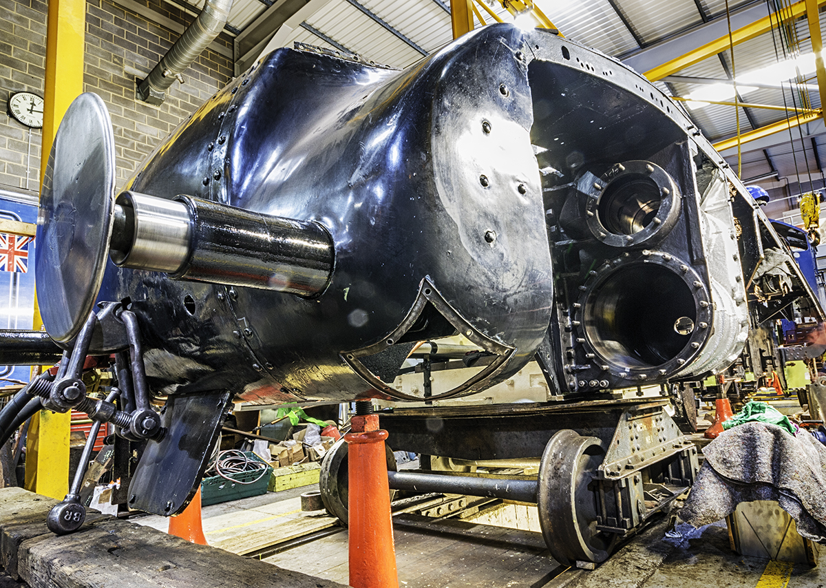
The front of the loco has been lifted and the accommodation bogie refitted. This was done as the bottom of the loco bogie stretcher has been finish painted and the new side bearers have been pinned in place. This means that the loco is mobile again and can be moved forward on to the wheeldrop.
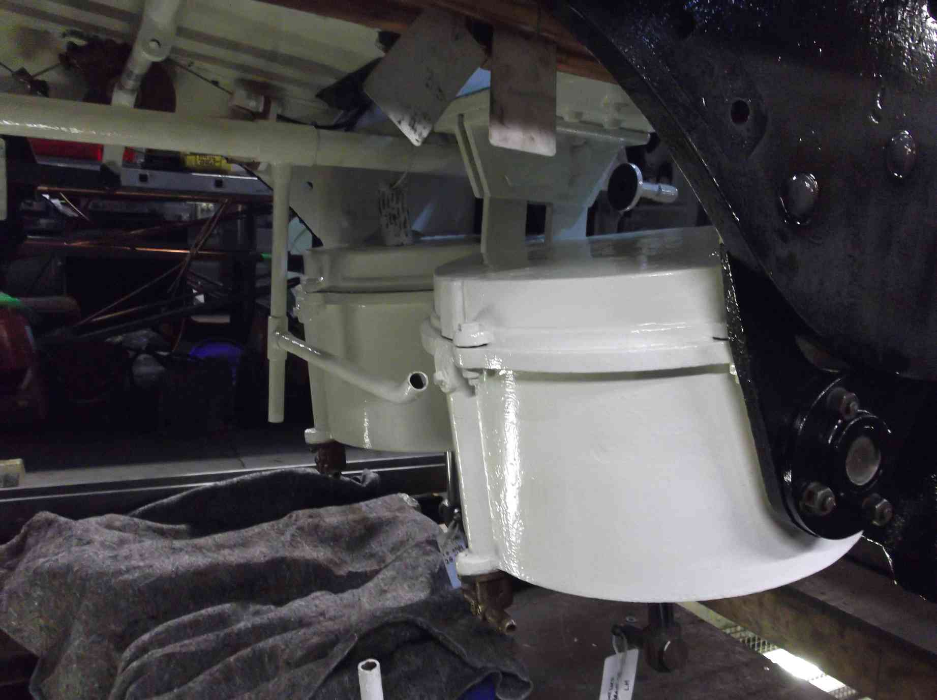
Putting the loco on to the accommodation bogie also allows the leading vacuum cylinders to be refitted. Not easy as they are a very neat fit and access for the crane from overhead is restricted by the frame stretcher the cylinders are suspended from. So the cylinders have to be positioned by hand.
Work continues on the tender vacuum cylinders with the fitting of new neck bushes. Both cylinders now have new neck seals and bushes fitted, and the piston rods tried in are a good fit. The cylinder mounting trunnions have been measured and new lining bushes made. They will be shrunk on.
The new slidebar shims are being fitted and the bolting closely examined. The examination has revealed that the fit between the right slidebar and cylinder casting is not satisfactory, so that the mounting hole in the cylinder casting has required careful adjustment. It also revealed that on the right side the nuts are not to drawing whereas the left are. I never noticed that before. This will be put right as new nuts will be required all round.
The testing of the cylinder drain cocks continues. Headway is being made in sealing and testing them.
The last of the conjugated valve gear components has now been inspected for defects. No faults were found. Meanwhile work continues on the expansion links with them being put on the milling machine for the trunnions to be skimmed before fitting with new bushes.
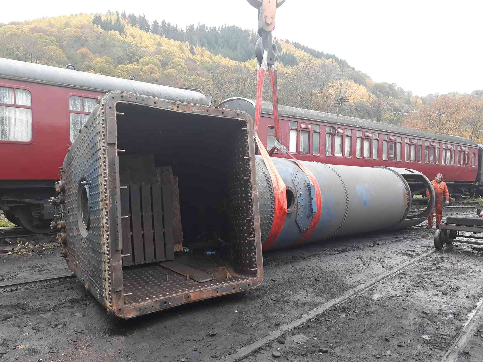
Our representative at Llangollen reports that the boiler is now ready for retubing. The final patch screws have been fitted to the copper tubeplate and the boiler has been positioned for tubing to start. Mud hole door seals have been ordered for the hydraulic and steam tests.
Weeks commencing 17 and 24 November 2018
Work on needle-gunning the tender around the water filler, coal dividing plate and the plate forming the back of the tender continues. Areas previously identified as relatively sound are now giving up their secrets. There will be more plate work to renew up here where body filler has contributed to keeping the corroded steelwork together and obscured its condition.
At the front of the tender tank the large cutout which allowed access in to the front of the tank has now been re-plated. Before this was fitted the new plate for the floor of the tank just inside was fitted and welded all round. A new angle plate that secures the brakeshaft safety link on the outside of the tank and is fitted below the new plate was made and drilled and the securing studs for it welded in to the floor.
More descaling has been carried out around the tender front bottom side sheets. This area was also thickness tested as we were concerned about the plate thickness and there are some little patches in it. It looks to be thick enough to take a little light patching and weld.
The welding up of the tender frames continues, a little at a time to avoid any distortion, and the tender wheelsets have now been painted inside to white undercoat. The tender rear footsteps have received more preparation for painting.
The renewal of the pipe systems continues to be steadily worked through. The steam heat and vacuum brake systems continue to be worked on but particular attention is now being given to the location of the air system runs in the tender frames. A mock-up was made to identify the clearances available between the tender tank, frames and wheels.
I had hoped to leave the tender vacuum brake pipe in position but the pipe fitting team decided it was better removed to be worked on. This is a single continuous pipe run almost as long as the tender. It was removed, examined and is now being repainted.
The flexible pipes that run from the hard pipe to the loco brake cylinders have now been fitted. The hoses fitted were to the size of the originals but some had received wear damage so a few shorter ones have been purchased and these have been fitted in some locations. The hard pipes in this area were slightly repositioned to better accommodate the flexi pipes. Some pipe end threads were remade as in repositioning the pipes required them to be dismantled which revealed some unsatisfactory threaded connections.
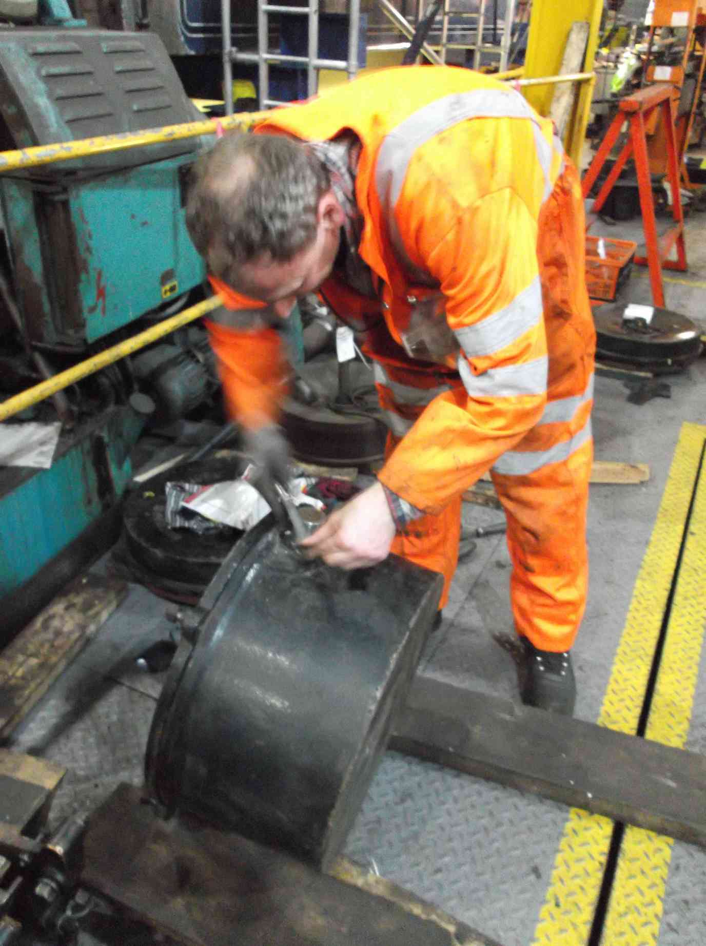
The tender brake cylinders have had their trunnions rebushed. The bushes were gently heated and dropped on to the trunnions. They were finally finished by filing them flush and chamfering the edges.
The bracket that secures the air pump governor to the loco has been modified to allow the output pipe to run straight forward. As the governor location was changed the pipe run is also being modified. Previously the output pipe dropped down but now it will be routed forward and up through the footplating, as 60009. The new run of the signal pipe to the governor is coming together by putting partial sections in place temporarily to ensure the run does not foul.
The refurbishment and fitting of the tender hornstays continues. The left side is now completed. This has been a time-consuming job requiring repairs to hornstays and frames, and careful, accurate fitting.
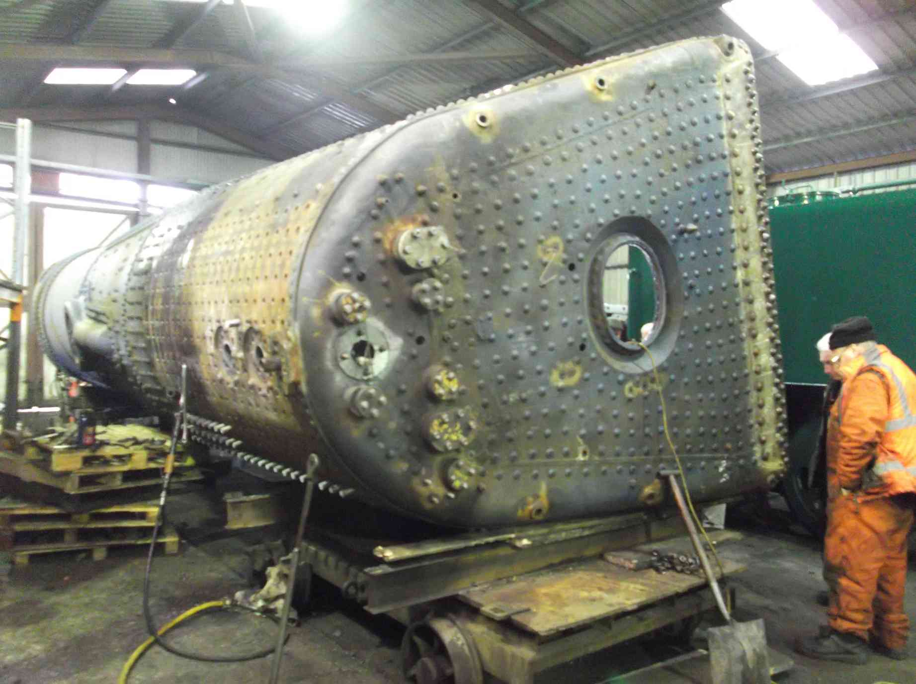
The major event for me over the last couple of weeks was our visit to Llangollen to visit the boiler. Tubing the boiler was to commence during the period under review, however the boiler insurers and our VAB needed to do a final inspection of the interior of the boiler prior to fitting the tubes. Obviously once the tubes are in, it would not be possible to access or view areas of the boiler that have been worked on during this overhaul. So the tubing was postponed and a meeting to Llangollen organised. The day before the meeting the superheater header, manifold and numerous other items were taken to Llangollen.
The next day the meeting between the insurers, VAB, Llangollen Engineering and ourselves was carried out. The boiler presently remains on it’s side while the crown stays are put in and finished. I’m no boilersmith but the finish on the fitting of the tubeplate looks very good.
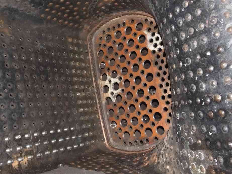
The head boilersmith is carrying out much of the work on our boiler personally and the finish of work appears to be very good. The paperwork generated during the boiler overhaul was reviewed by the insurers and all was found to be in order.
The AWS battery box refurbishment continues. Various old holes that were plugged with silicon have been cleaned out and welded up and the box is now on the painting bench.
The coupled axlebox fitting progresses, though slowly at the moment due to Llangollen visits and other time-consuming but necessary distractions. The underkeeps are now fitted to four of the axleboxes. Fitting the underkeeps requires the fitting tolerance to be maintained and the pin lengths to be checked in the final fitted underkeep to ensure they will not foul the horn faces on the loco. Two axleboxes remain to be treated as one is presently being scraped on to its journal and another is still with contractors for repairs to the white metalling.
When the wheels are refitted the new horizontal hornstay bolts will be fitted. These bolts are now receiving final machining to match each individual location.
New outside crank pin bearing castings have now been received. They are now in the process of being roughed out. Meanwhile the trunnions on the expansion links are being rebushed. One set is now back at York to be reassembled and mounted on centres to measure the alignment.
The new bottom flanges for the safety valves have been received and inspected. They comply to drawing.
The fitting of the new shims to the slidebars continues. The measuring wire has been put up on the middle cylinder and the alignment of the slidebar checked. One of inside shims has required further fitting and this is being carried out and measurements taken. A report has been produced of the condition of the bolting so that we can sort purchase or manufacture of new bolting.
This is the 34th update—you can read all the previous instalments here.
This is fascinating. It would interesting to know if the original engineering drawings for this loco still exist and how much of the loco still matches them.