Week commencing 1 October 2018
The tender tank had steel plate inserted and welded in position this week. This fills the holes in the water filler space side sheet. Work continues on fitting new plate to the bulkhead that separates the coal space from the water filler space. Now it’s cooler in the workshop on top of the tender productivity is returning to normal.
More work has been done on the front of the tender with the removal of the rivets holding the bottom plate on to the original 1928 side angles. We also had a visit from a steel supplier to measure up, as they have been asked to quote for the supply of new plate. Our normal suppliers are on Teesside, but for large pieces of plate we would incur delivery charges.
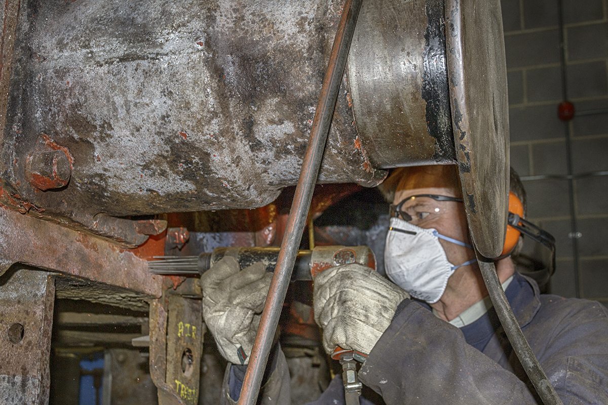
Work has continued this week on the tender frames with needle-gunning of the frame plates complete, attention is now concentrated on the dragboxes. The frames are now being closely inspected so that a refurbishment programme can be planned. The measurement of the frames, axleboxes, wheelsets and bearings continued this week. Cleaning and painting of the wheelsets continues.
The neck bushes were removed from the tender vacuum brake cylinders and a start has been made on the manufacture of new ones.
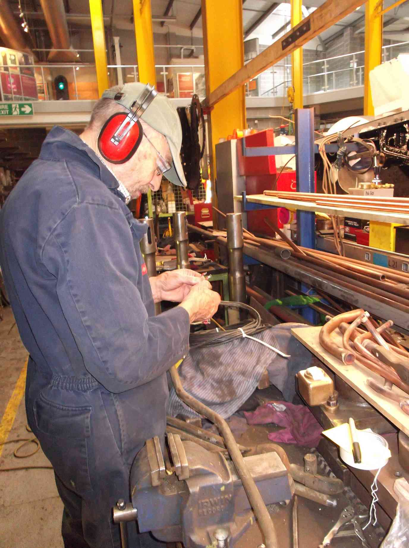
Work continues on the replacement of some of the smaller-diameter air system pipework, replacing it with pipe more resistant to damage. The problem is that to identify the existing pipework type, fittings have to be de-soldered and removed, though our volunteer leading this job is adept at identifying pipe types by weight.
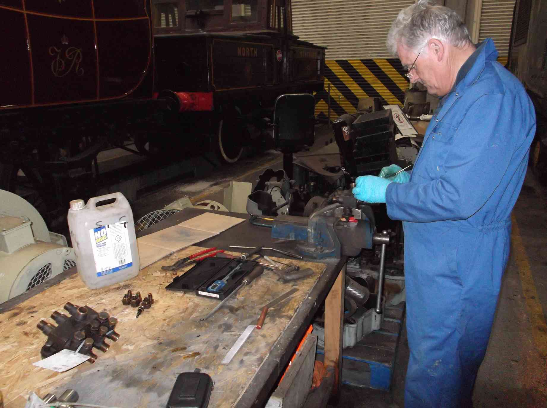
Work has also progressed on the manufacture of new pipe clamps for the lubrication pipes and the atomisers have been retrieved from store for refurbishment. The atomisers are in the process of being dismantled and the internals cleaned out and inspected.
We now have all six coupled axleboxes on site and preparation work for their refitting in under way. The axleboxes have been cleaned down and a start has been made in the manufacture and fitting of the locking screws for the thrusts.
The brackets that fit in the bottom of the axleboxes, on top of which the underkeep oil baths fit, were tried in this week. They have to be fitted before the axleboxes go into the frames. More work is required on fitting these. The brackets have a large pin passing through them and the axlebox, from which the main spring is fastened. These pins wear and eventually require replacement. We now have a full serviceable set as where required new have been made at York.
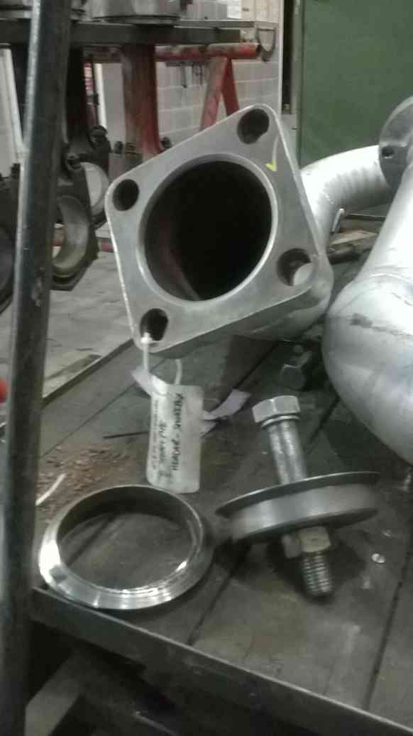
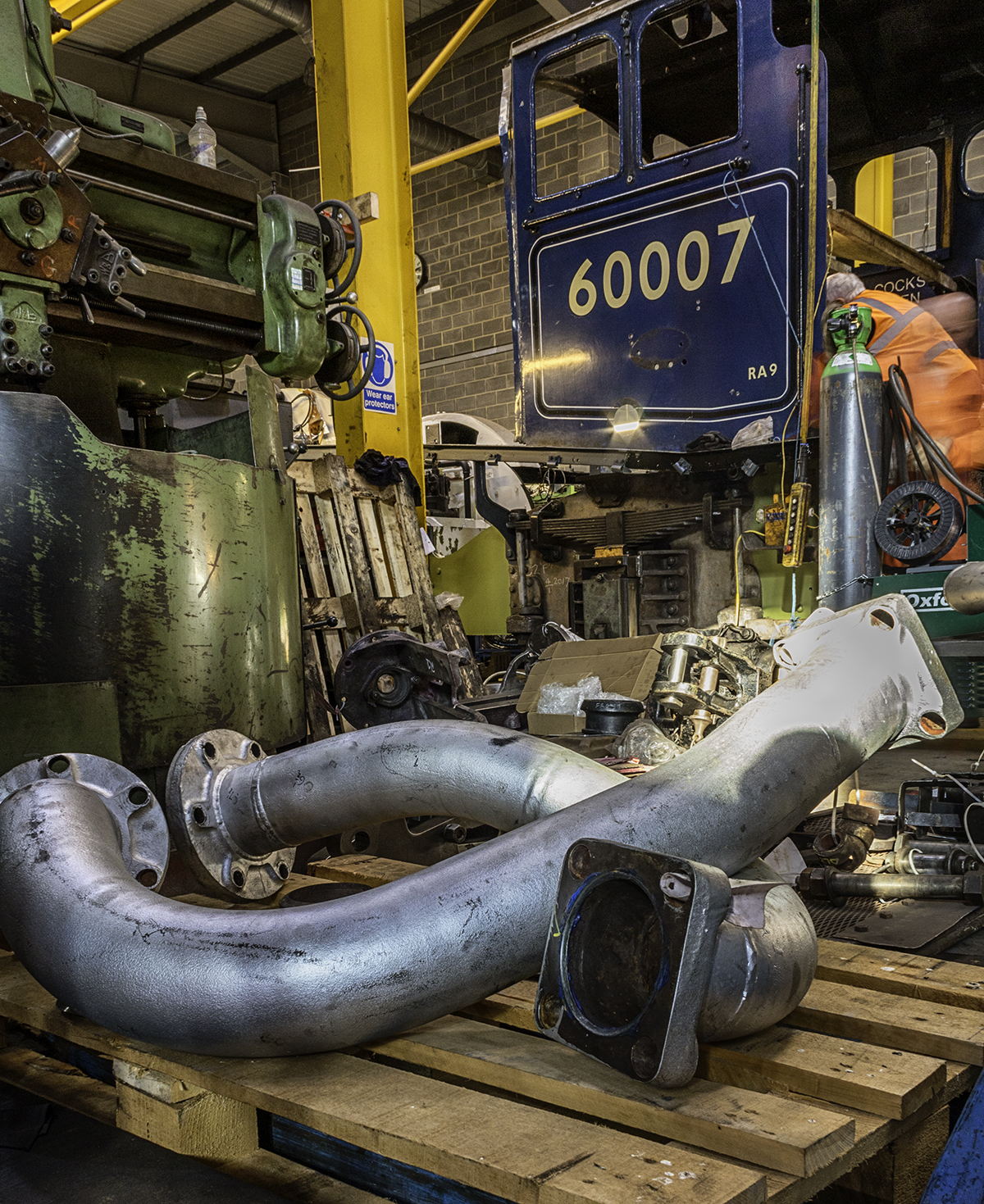
The steam pipes from the supeheater header to the cylinders are to be pressure tested. This week the faces of the pipe flanges were lapped with a tool made at York and the lens rings cleaned up.
The front coupling hook was fitted with a lock nut this week after being made from one of the old nuts, and the cotter to the end of the hook shaft was fitted. The cotter again being original but requiring modification to fit the new arrangement.
Weeks commencing 8 and 15 October 2018
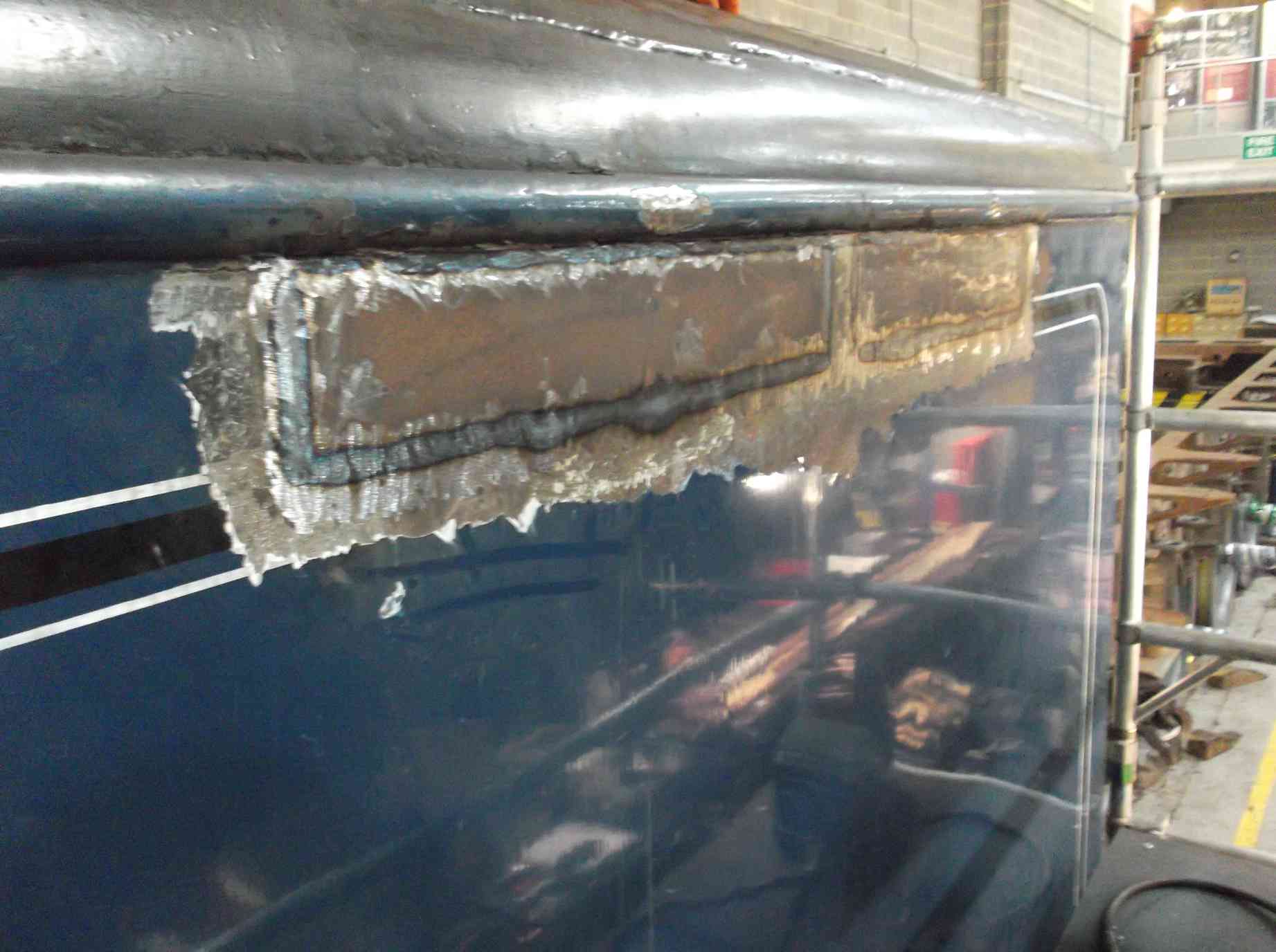
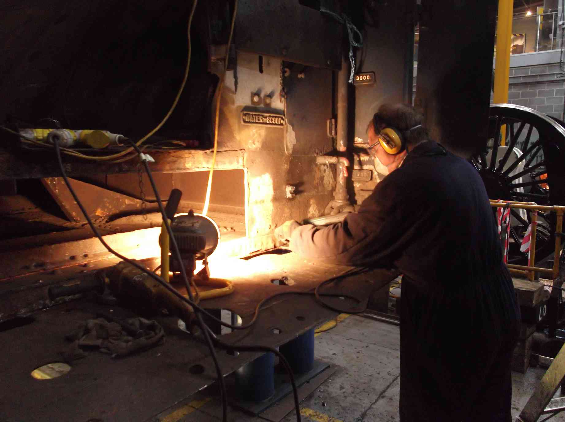
Surgery continues on the tender tank in the water filler space and preparing the area around the front of the tank to receive new plate. The area just inside the front of the tank was ground and wirebrushed so that new plate can be welded in. The larger pieces of new plate have now been delivered from a local supplier. Other pieces that can be transported more easily will be supplied from Teesside where steel is cheaper. The rivets holding the tender floor to the original 1928 side brackets were burnt out as part of the the floor plate removal.
The inside of the tank has seen some cleaning out by the 007 Gang of junior volunteers. The team also started the removal of the tender front water gauge as access below it is required to access the floor plate for replacement.
The descaling of the leading tender dragbox has now been completed. The rear dragbox is being continued. The frame stretchers and internal pipework left in place are now being stripped and descaled. With the tank off it will now be possible to simplify the routing of the TPWS electrical conduit and some air system pipework which was fitted with the tank in place. The TPWS conduit has been removed along with its brackets. The brackets were supported by a rather flimsy length of angle and the pipe fitting and electrical teams decided it should be replaced with something more substantial, so the old has been cut out. The electrical conduit and fittings required have been listed and are in the process of being obtained.
The AWS electrical system overhaul continues with the battery box refurbishment. The solenoid valve that operates the cautionary horn in the cab has been electrically tested.
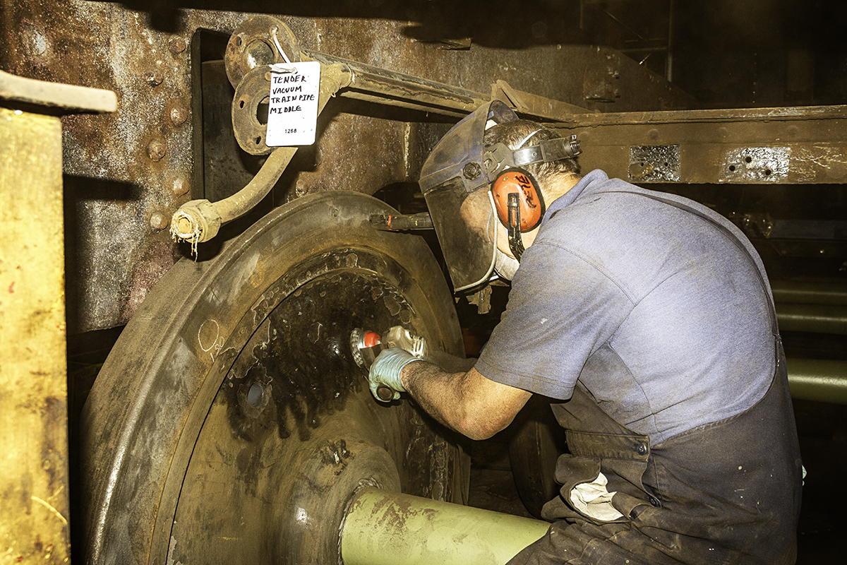
While needle-gunning around the tender frames continues, the wheelsets have received further painting in primer and undercoat. The tender draw gear rubber springs and plates are now being cleaned down and examined. They are suitable for further service so the plates, originally galvanised mild steel, have been painted with a zinc paint. One new plate is required and this is on order and to be made in stainless steel.
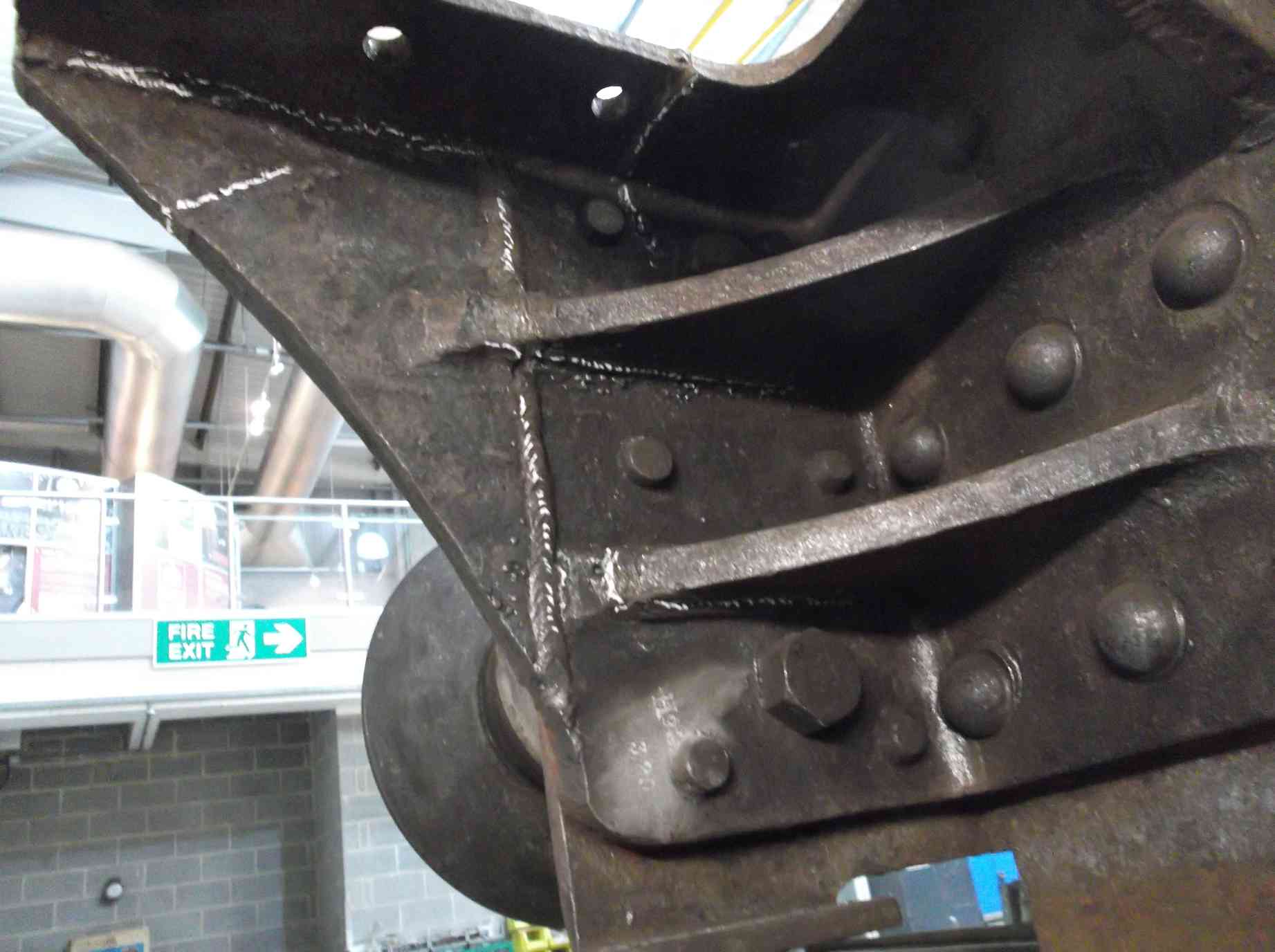
The leading tender frame angle tops are wasted and it was decided they should be replaced with new plate. The flanges were burnt off and existing metal prepared for welding on the new flanges. New metal has been trimmed to size and is tacked in place for final welding.
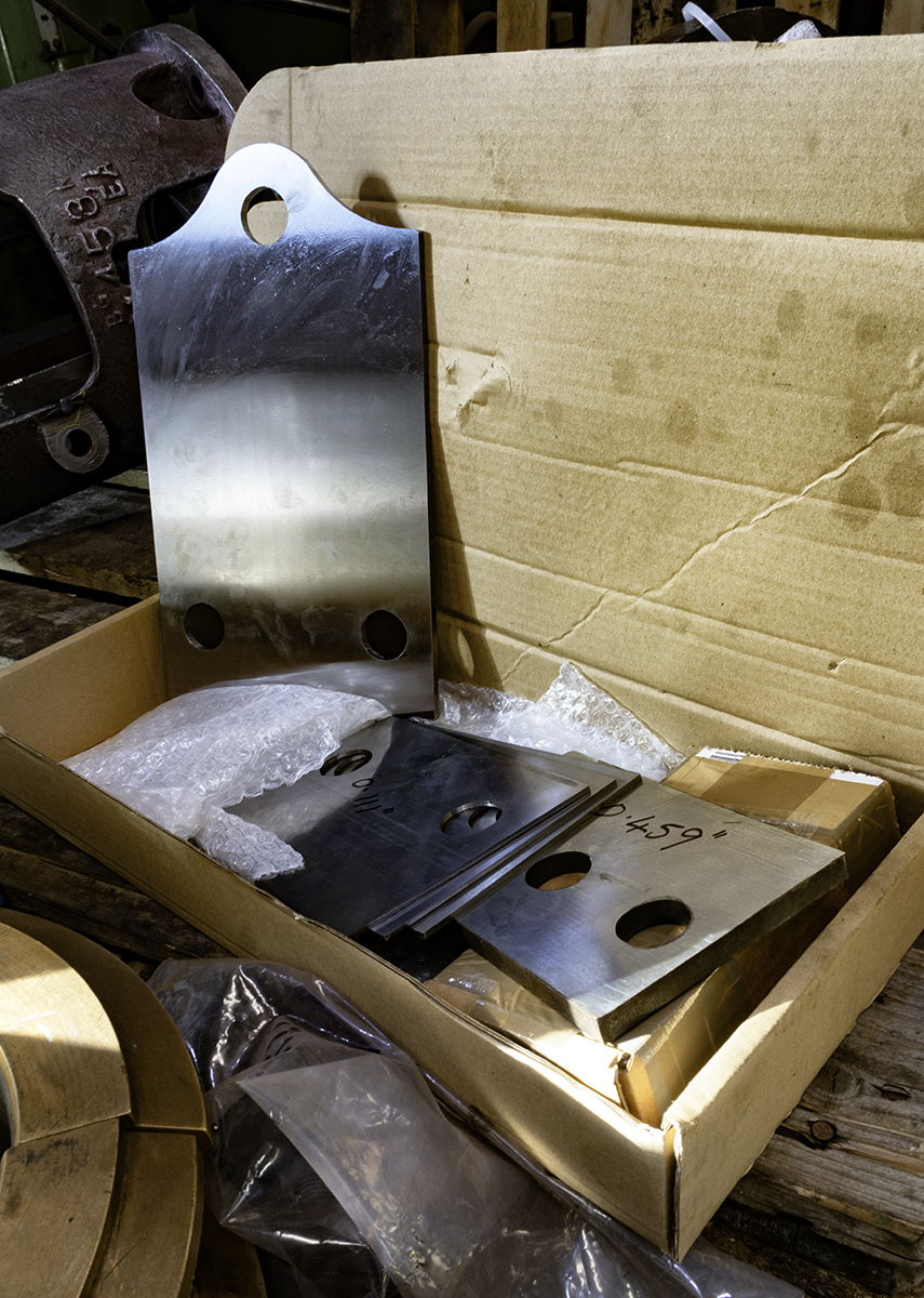
The detailed examination of the tender frames continues with only one loose rivet found, which has now been removed. The area of frames at the leading end are wasted in places and these will be thickened by the addition of weld. Welding the frames will have to be carried out by a coded welder and be accompanied by documentation. A start on the prep for this was made by grinding back to bright uncorroded material which will accept a good weld. More needs to be done. A supporting beam will be fitted between the frames to ensure the frame spacing is not affected during welding. The end plates for the beam have been made.
The measurement of the tender frames, wheelsets and axleboxes has now been completed with the distance across the frames between the horns being taken. The results will now be tabulated and the required dimensions for the brasses calculated. The tender wheelset journals are now being dressed.
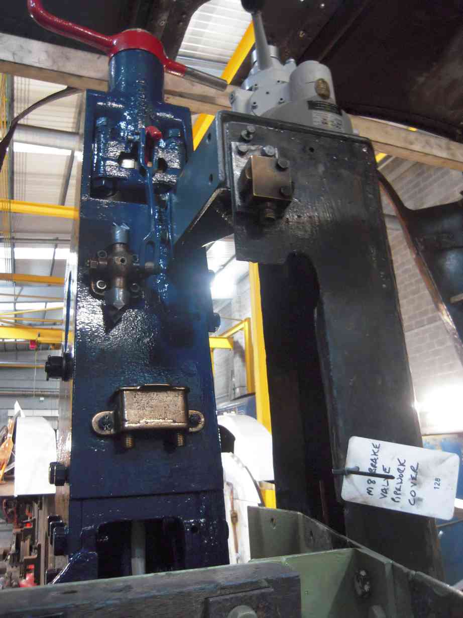
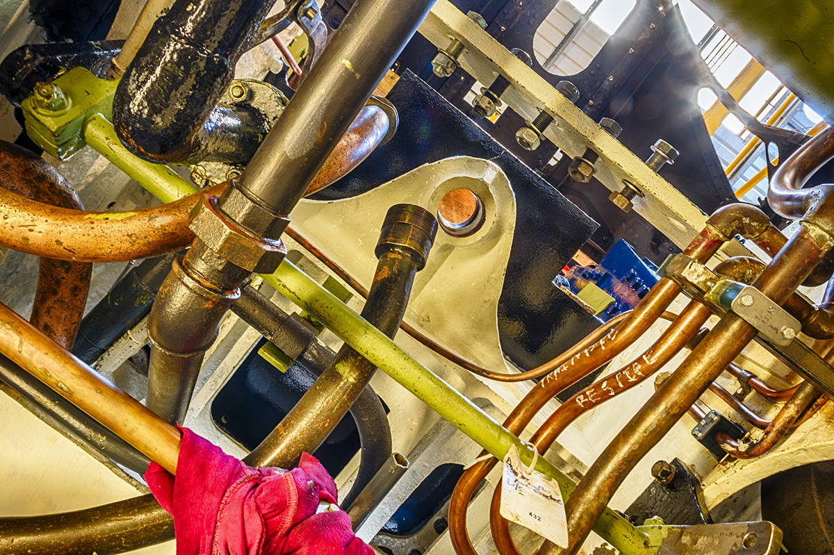
More pipework inside the loco frames has been replaced where thicker-walled pipe is required, and pipe to the M8 drivers air brake valve is now being positioned. The reverser stand has now been fitted to the loco. This is quite an operation as it requires the removal of the cab. With the reverser in position this allows the fitting of the M8 as it is mounted on a bracket hung off the reverser.
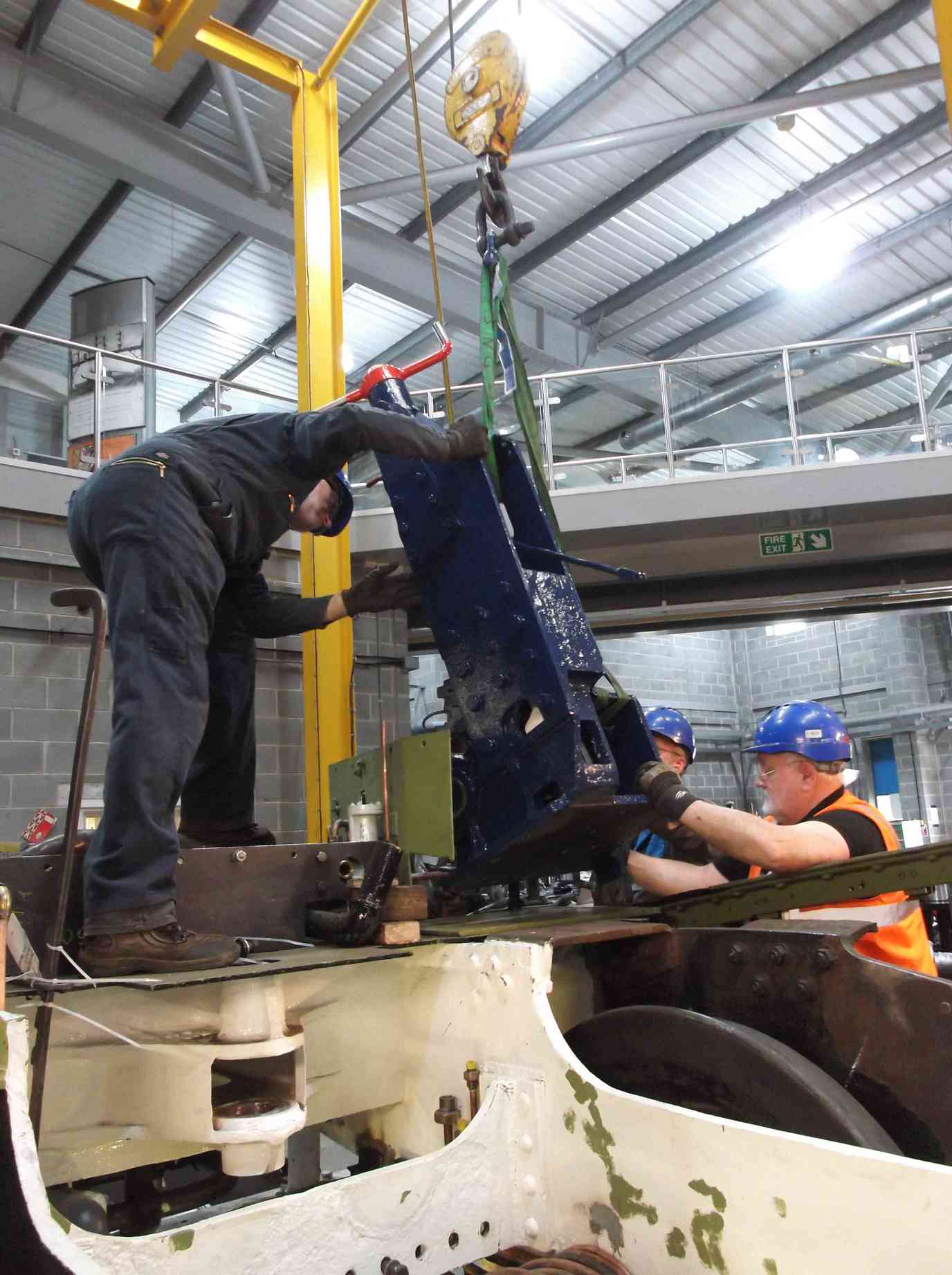
When the reverser was in, the floor support rests on the reverser flange. This means that the floor needs to be removed before the reverser, in addition the floor support is not secured at the reverser, so a new arrangement has been made that secures the floor support to the loco and is clear of the reverser, and this adds more rigidity. The pipe-runs around the reverser were examined and are clear. A board representing the cab floor has been fitted and the casing below the M8 fitted. Again there was no fouling of pipes, though it has been suggested that the casing be renewed as it bears witness to hundreds of strikes of the fireman’s shovel.
The atomiser refurbishment is continuing. All the seats and parts inside the atomisers have been removed and all the small steam and oilways tested to make sure they are clear. A number of seats require renewal.
The coupled wheel axleboxes are being examined before fitting to the journals. The horn faces have not been re-metalled but have needed dressing to remove burrs and damage from the oilways and around the spring hanger holes.
The last of the axlebox thrust securing screws were made and fitted. The tender brake cylinder bronze neck bushes are now being made.
The screws securing the thrusts have now all been cut and finished flush with the surface of the axleboxes. They need to be flush to allow the fitting of the oil seal. Measurements have been taken of the axleboxes and the spring hanger brackets and this will be recorded before the axleboxes are refitted. The axleboxes were put up on the surface table and horns measured for parallelism so that we can estimate the amount of fitting that will be required. Meanwhile, three of the six spring hangers have now had new bushes fitted.
The right-driving crankpin dressing has been completed, and the slidebar shims have now all been ground to size.
The bottom flange of the leading safety valve has been examined and a drawing for new has been produced. It was checked and we are now getting quotations for manufacture. We now have quotations for the casting of the bronze coupling and outside connecting rod bushes so we can now progress to getting them ordered.
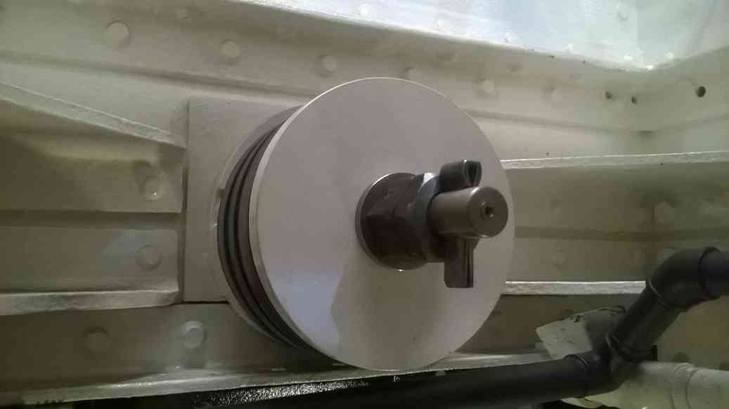
Bolting was obtained for testing the steam pipes and a plate to seal the end of the pipes during test has been machined. A couple of the pipes were clamped together and pressure-tested satisfactorily to the boiler test pressure.
At Llangollen the ashpan has been fitted to the upturned boiler. As expected a little bending is required to get a close fit to the foundation ring. The front of the ashpan fits really well and the remaining gaps will be closed by heating and forming the ashpan flange.
Week commencing 22 October 2018
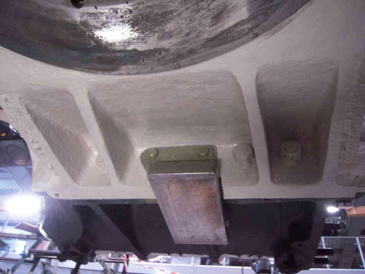
The bogie sidebearers after final welding are now refitted to the loco with close-fitting pins. The overall dimensions of the brackets have been taken and the fitted bolts can now be finish-machined. The bolts are already pre-machined and just need the fitted diameter and their heads finishing off.
The last three coupled wheel spring hanger brackets have had new bushes machined and fitted. The coupled axlebox cover plates have been dressed and are now being painted. The removal of burrs and minor marking to the white-metalled horns was required to allow accurate measurement. The dimensions taken over the last couple of weeks have been analysed and it was decided that some fitting along the horns is required. This is ongoing.
The pressure-testing of the steam pipes has continued this week. The steel pipes are now completed and have tested satisfactorily so attention has now moved on to the cast-iron ones that fasten on to the tops of the cylinder castings. Being iron they need a little more cleaning up and require plugging along their lengths as there are entries for lubrication, pressure take offs etc. The entry threads are being cleaned up and are in the process of being plugged.
Needle-gunning is continuing on the trailing tender dragbox. The leading and trailing dragboxes have also been measured to assess the degree of wastage these castings have seen. The trailing dragbox measures in excess of the original drawing specified thicknesses in many places and apart from surface corrosion does not seem to have lost any significant material. The leading dragbox has seen wastage, the dimensions have been recorded, and will be considered.
The frames at the front of the tender require rebuilding as they are wasted below acceptable thickness. A beam has now been fabricated and this is fitted across the front of the frames, hopefully preventing any distortion of the frames when they are welded.
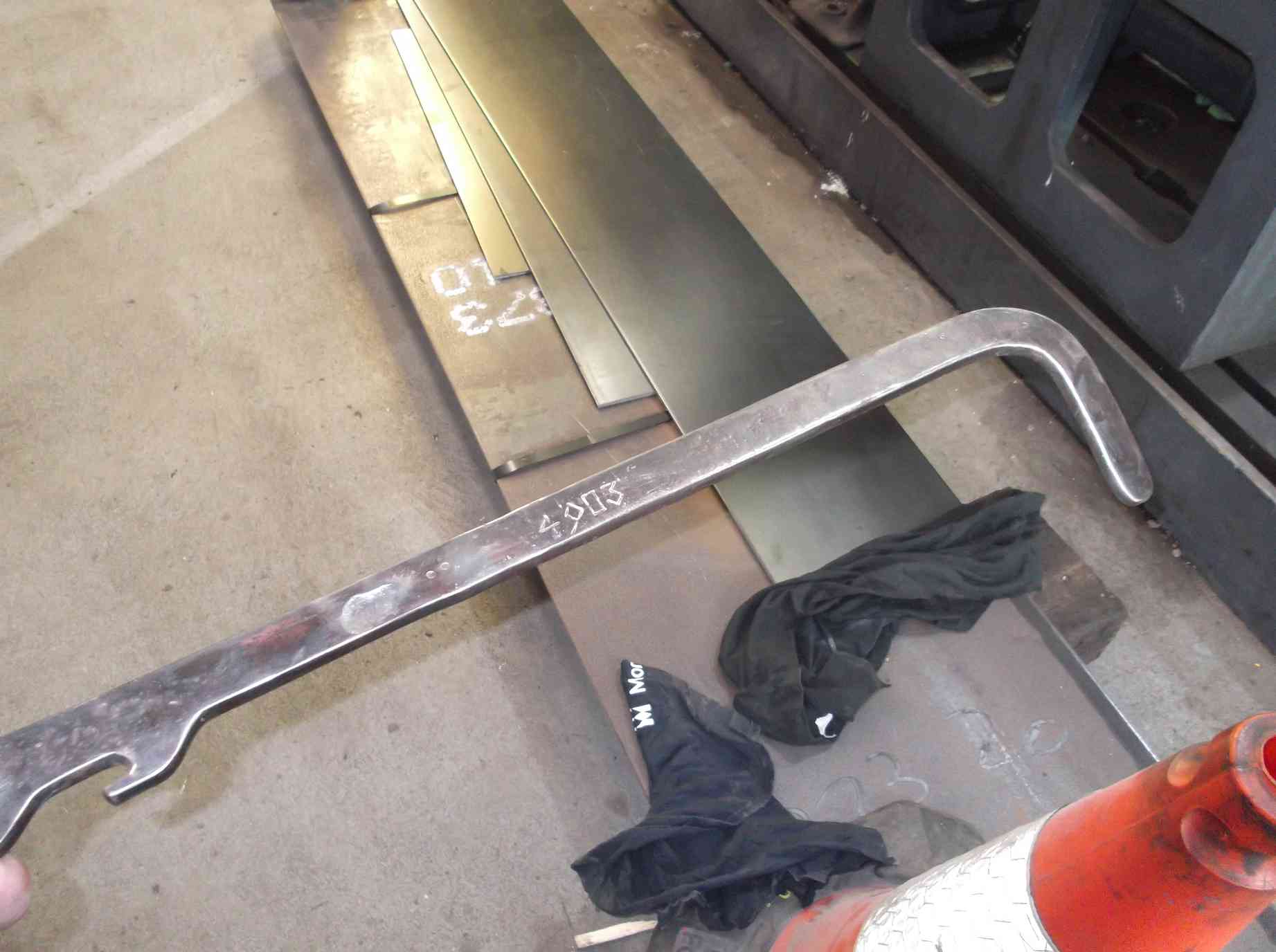
The tender frame hornstays are now in the process of repair work to improve their fit onto the frames. These are an important structural component and their fit is important to prevent damage to the frames. The hornstays will be rebuilt with weld and this will be then carefully taken back until a good tight fit on the frames is achieved. The first is now being worked on to identify a procedure that we will be able to apply to the rest.
Inspection and testing of the tender spring hanger brackets and horn cutouts is continuing. The spring hanger brackets show evidence of numerous weld repairs in the past so take a careful looking at. The tender wheelset journals are being dressed to remove wear marks under the outer flange and this work has continued this week.
The tender brake cylinder overhaul continues with the right-hand cylinder being machined to remove damage and wear to the mounting trunions. The cylinder was taken to the works of K D Flavell and put on their borer. The machined trunnions are now ready to be bushed, following an approved BR repair procedure.
Pipework around the M8 valve continues while the pipe-runs through the tender frames are also being progressed. New material has been obtained and cut for the support brackets for the electrical conduit and air system pipework. New conduit and fittings have been obtained for the TPWS cable runs.
Below the cab the damper handle and cross-shaft pinning is completed and the cross shaft has been finally fitted.
The middle valve gear middle valve spindle extension has been cleaned and prepared for test. On the outside gear a liner has been fitted to the inside-right expansion link trunnion bearing housing. This was drawn into the housing as it is a tight fit. The liner was then finished to provide a good fit on the bearing. The final dressing of the outside driving crankpins was completed last week and this week they received a final polish.
Week commencing 29 October 2018
Pressure-testing of the cast-iron steam pipes has had to be put on hold as a crack has been discovered in one while the sealing face was being prepared. A repair will be necessary. Considering the condition of the other pipes they have obviously seen a long service life so more comprehensive refurbishment work on these pipes is now being planned. The rationale being if we have to pay for casting repair we should take the opportunity to carry out refurbishment work on a couple of other war wounds.
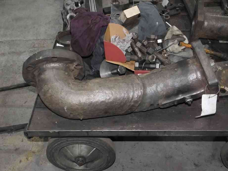
These steam pipes have been measured for thickness and though they have clearly lost material through wastage they are still serviceable. To ensure we have a full record of the pipe thickness along their lengths more internal decarboning will be required.
To keep the pressure-testers busy we have moved on to testing the cylinder relief valves. The first two were tested this week, with less-than-satisfactory results so we are investigating why.
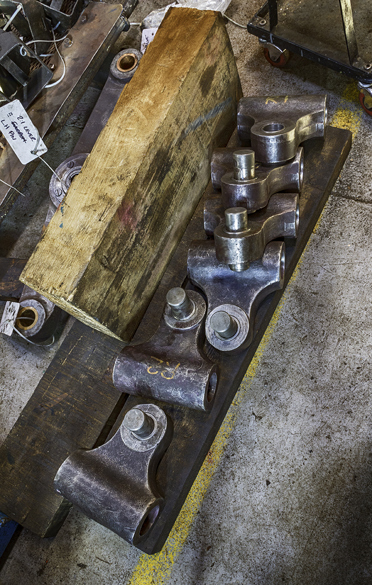
The buckeye coupling overhaul progressed by stripping this week. We are following the original BR overhaul instructions which details permissible wear and repair procedures. This work is ongoing.
As with the buckeye, most working hours are now being spent on the tender. This week the new plate for the tender front-bottom plate was lifted and fastened to the exiting plate. The new plate was then marked through and drilling of fastening holes in the new plate is progressing.
There are larger cutouts to be put in for the drawgear pins and water valve rods, but we didn’t have access to the burning gear this week. However, good progress has been made. The area inside and out where the old bottom plate will have to be removed has seen further preparation by the removal of scale, paint and filler.
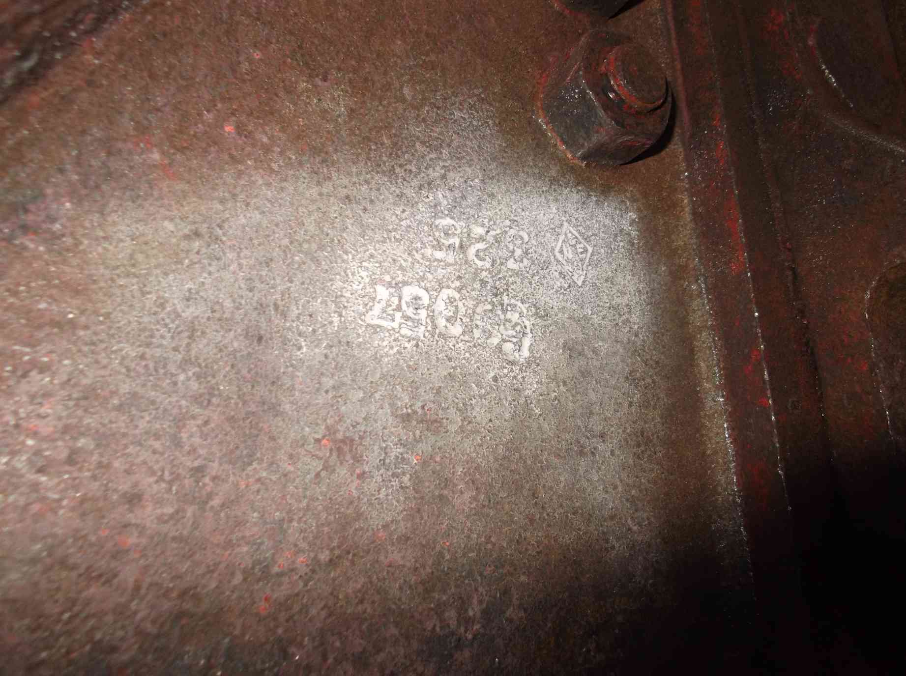
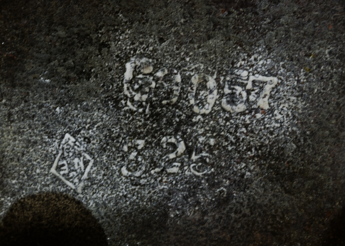
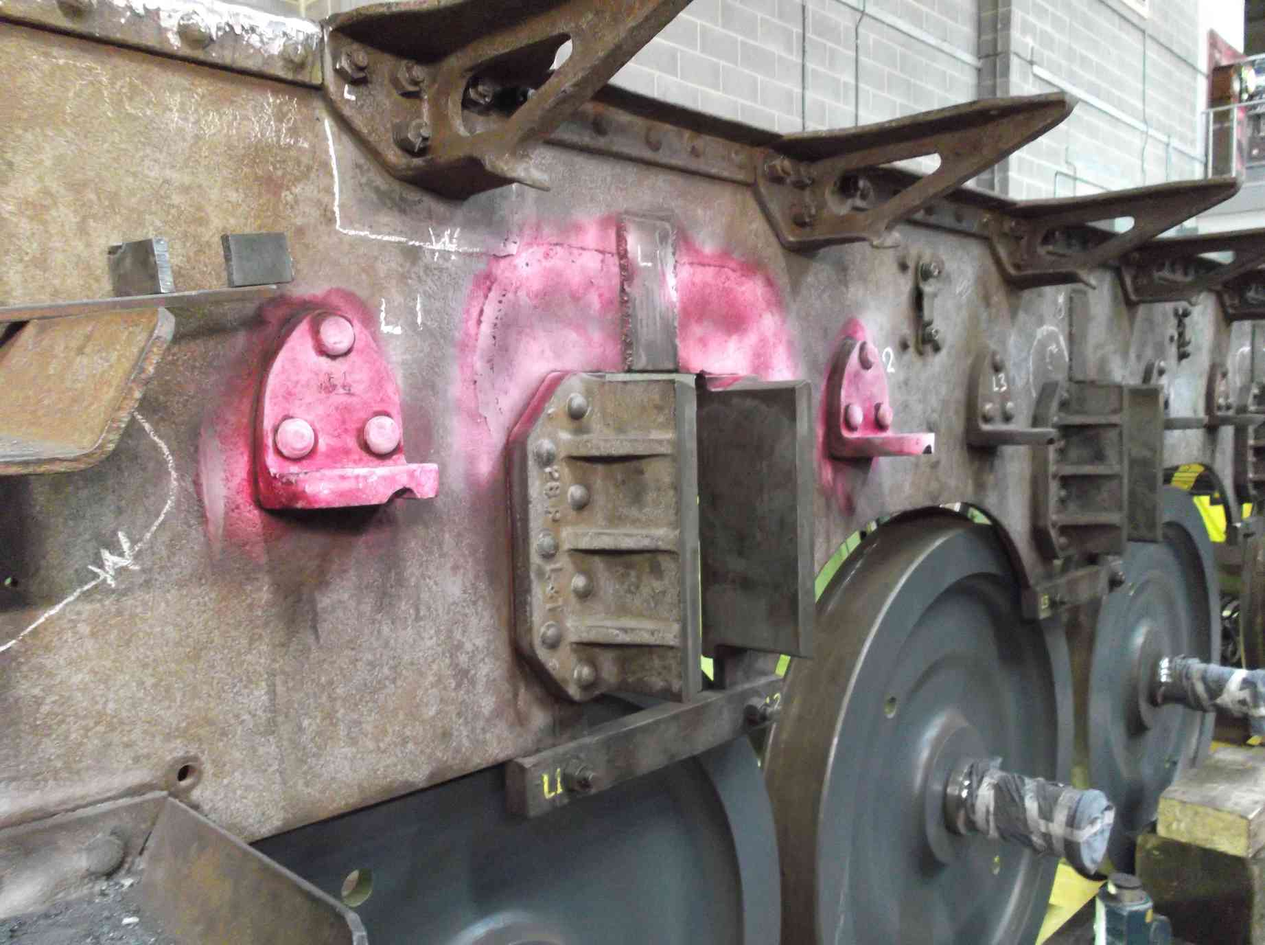
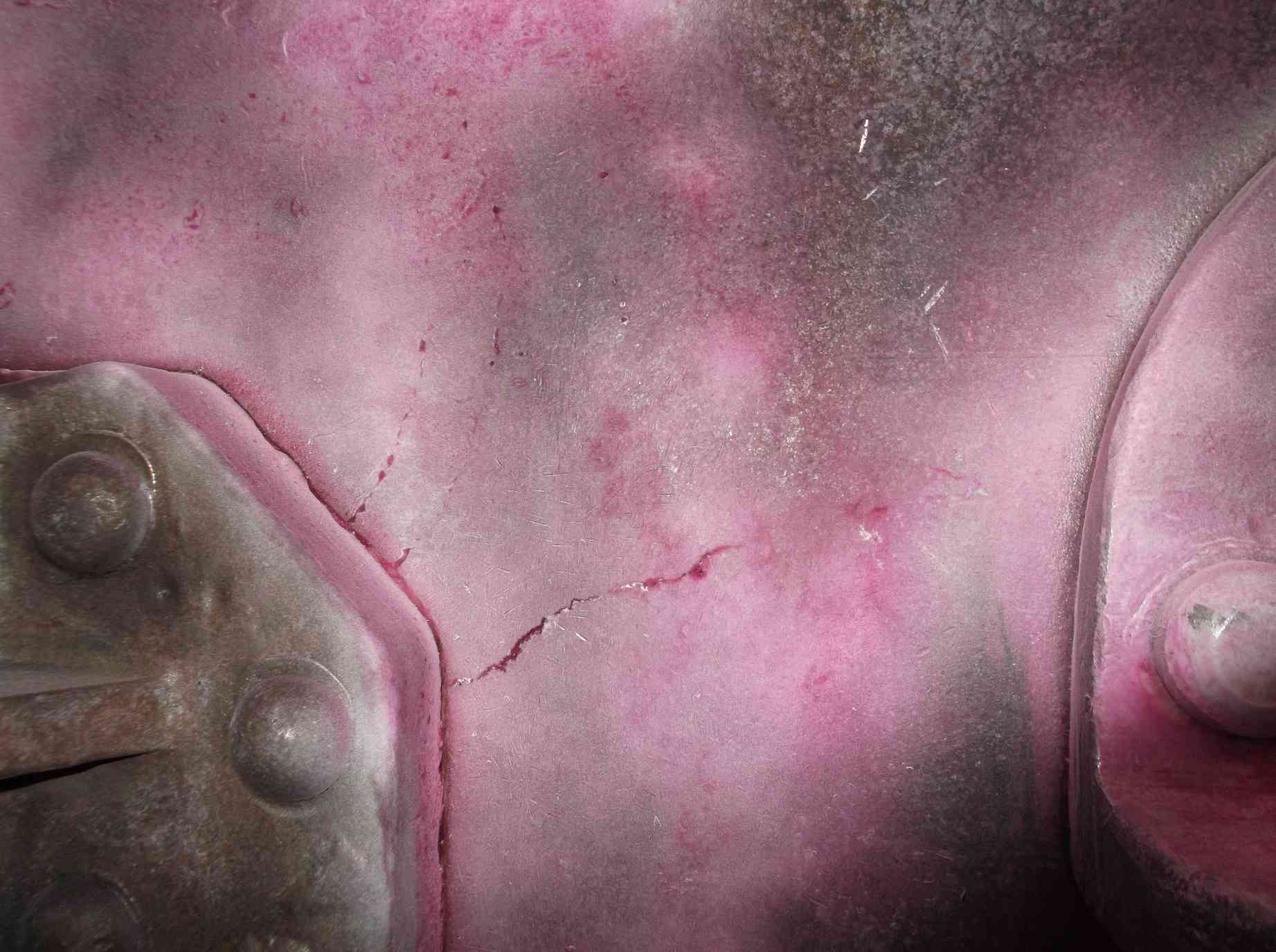
The inspection of the tender frames continued this week with the completion of the testing of the spring hanger brackets and the horn cutouts. Next to one of the cutouts was a rather alarming looking crack perhaps six inches long. As these areas on the frames have seen previous repairs for such defects I thought this may lead to another major frame repair, however testing did not indicate any great depth. The defect was ground out by the removal of the surface skin of the plate. It appears that it was a surface defect rolled in to the plate, possibly at the Parkgate Foundry, Rotherham when manufactured c1928.
Inspection and testing of the tender frames also included the leading dragbox and the leading two frame stretchers, where a couple of failed rivets were found. The first of the refitted tender hornstays was completed this week and is now a satisfyingly snug fit. The second hornstay is now being worked on.
The dressing of the tender wheelset journal ends continued this week by Chris Whiteley, and a fine job is being done. The last one is now well on the way to completion.
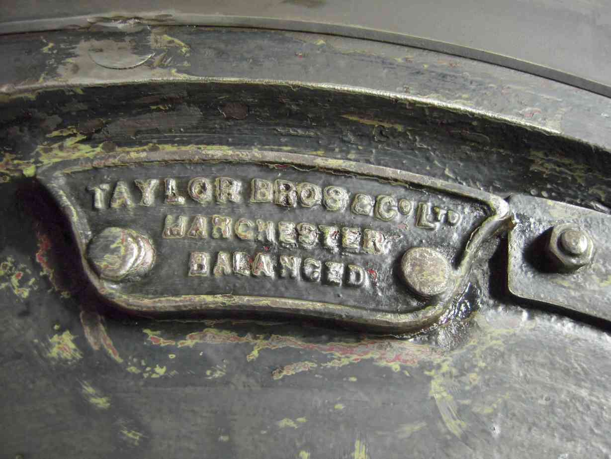
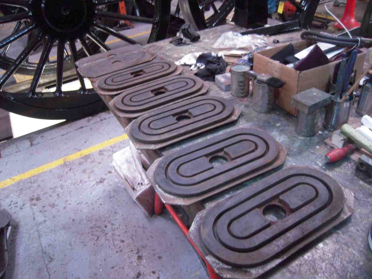
The blocked mounting hole in the front tender balance weight was drilled out this week as part of its refurbishment before refitting.
The trailing dragbox received more descaling this week. The AWS battery box and associated components continue their refurbishment.
The machined tender vacuum cylinder was returned to York this week.
Work continues in the cab on piping, on rerouting of the steam and air supplies to the repositioned governor. Quotations for the steel pipe and fittings for the tender and the steam supply to the governor have been obtained.
The middle valve gear has now all been collected together with the last pins and the outside valve spindle extension links retrieved from store. All are now being examined for defects and measured to determine if they are suitable for further use.
This is the 33rd update—you can read all the previous instalments here.