Week commencing 13 August 2018
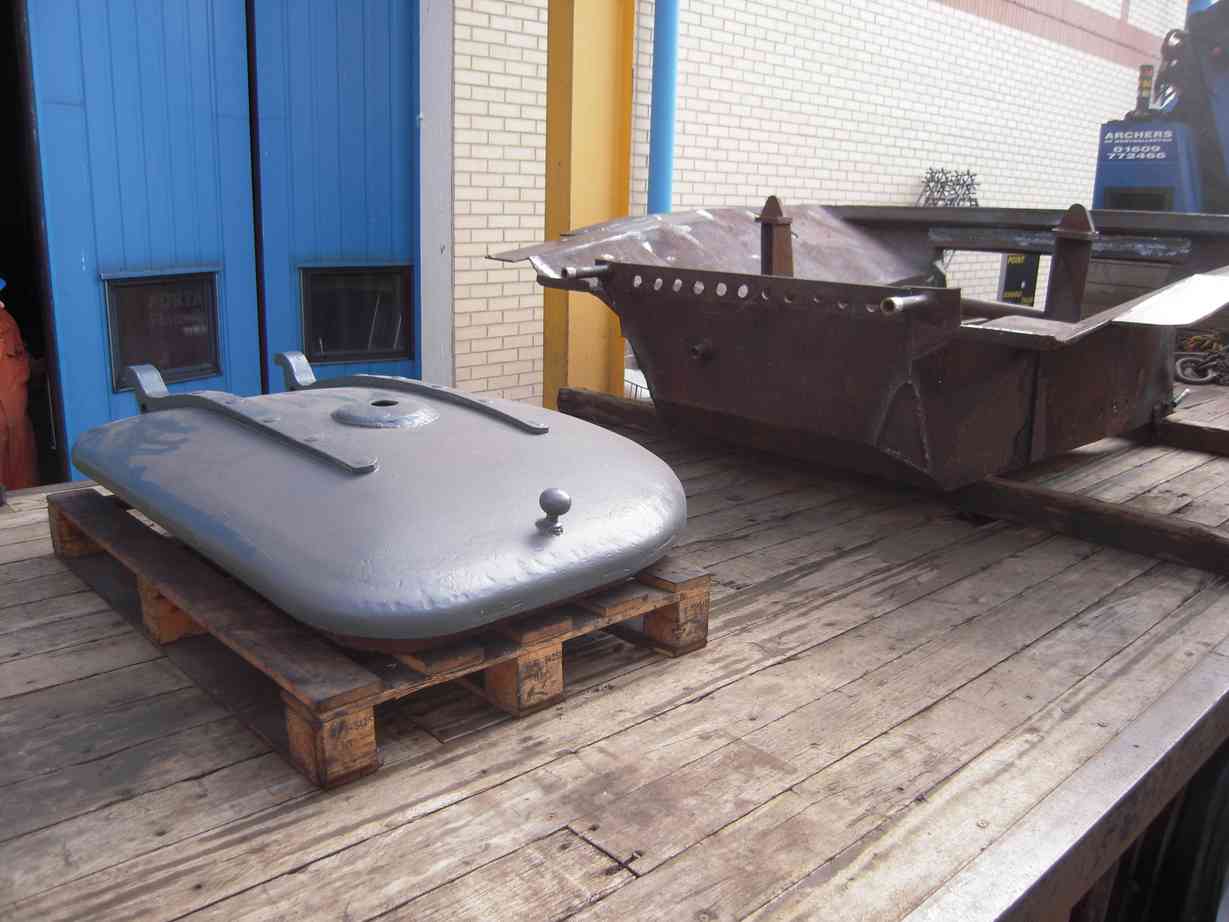
At the beginning of the week a number of items were sent to Llangollen to join the boiler. The major items were the ashpan and smokebox door. Later in the week our CME and I went over to Llangollen to look at progress on the boiler. It is still upside down, which will allow the ashpan to be lowered onto the foundation ring and should make fitting it easier.
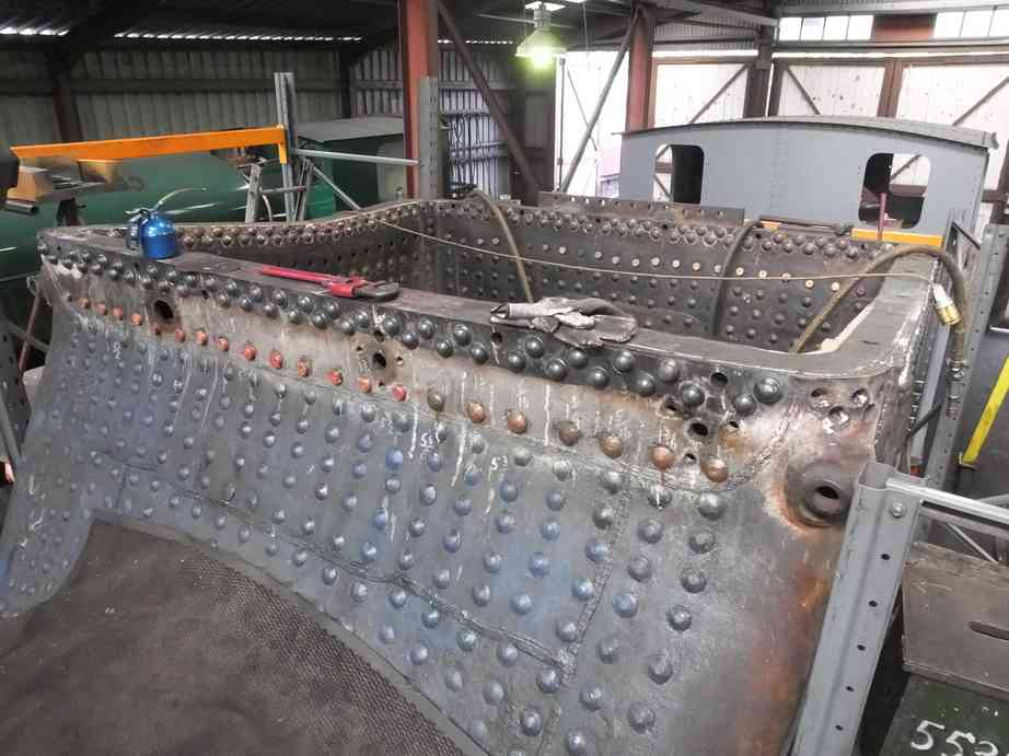
It was the first time I have seen the boiler with the foundation ring back in position and progress has been made in fitting all the rivets and trimming and caulking the plates. Work continues on caulking and dressing the rivet heads on the outside of the foundation ring. The gauge frames have been tried in place and gauge glasses tried in during our visit to ensure the frames line up so that the glass tubes are not fouled. Everything appears to be OK.
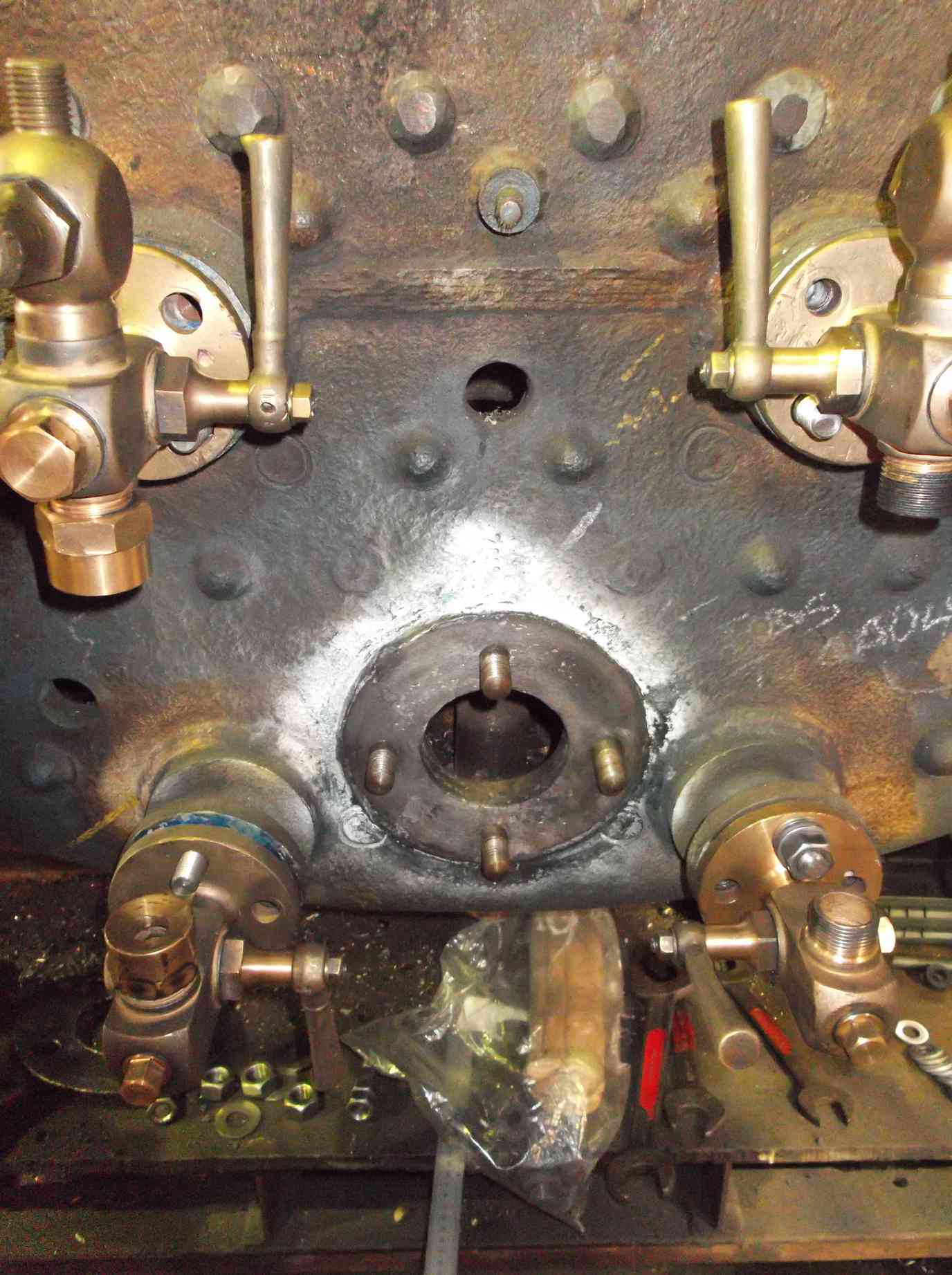
While there, the regulator stuffing box was removed and the flange face on the boiler was examined. This is a critical joint that is very difficult to get to when the loco is in service. The face has been fitted accurately to the stuffing box after it was repaired.
One of the main purposes of our visit was to discuss the final testing of the boiler, to ensure all parties expect the same procedure. We plan to test many of our boiler fittings on the boiler so that they are proved during testing and this was discussed.
We had hoped to send the superheater header to Llangollen on the same transport but we want to test it to higher pressures than we have yet achieved. During testing we had trouble maintaining pressure in excess of 250psi due to a seal extruding from below a sealing plate. This was identified as being caused by the plate flexing. New thicker plates were obtained and they have been drilled to fit them. A bit of work was also required to get one of the plates to sit flat on it’s gasket. All is now ready to be resealed and tested again.
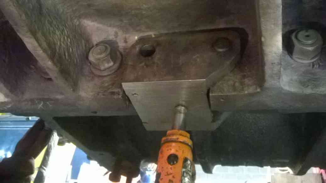
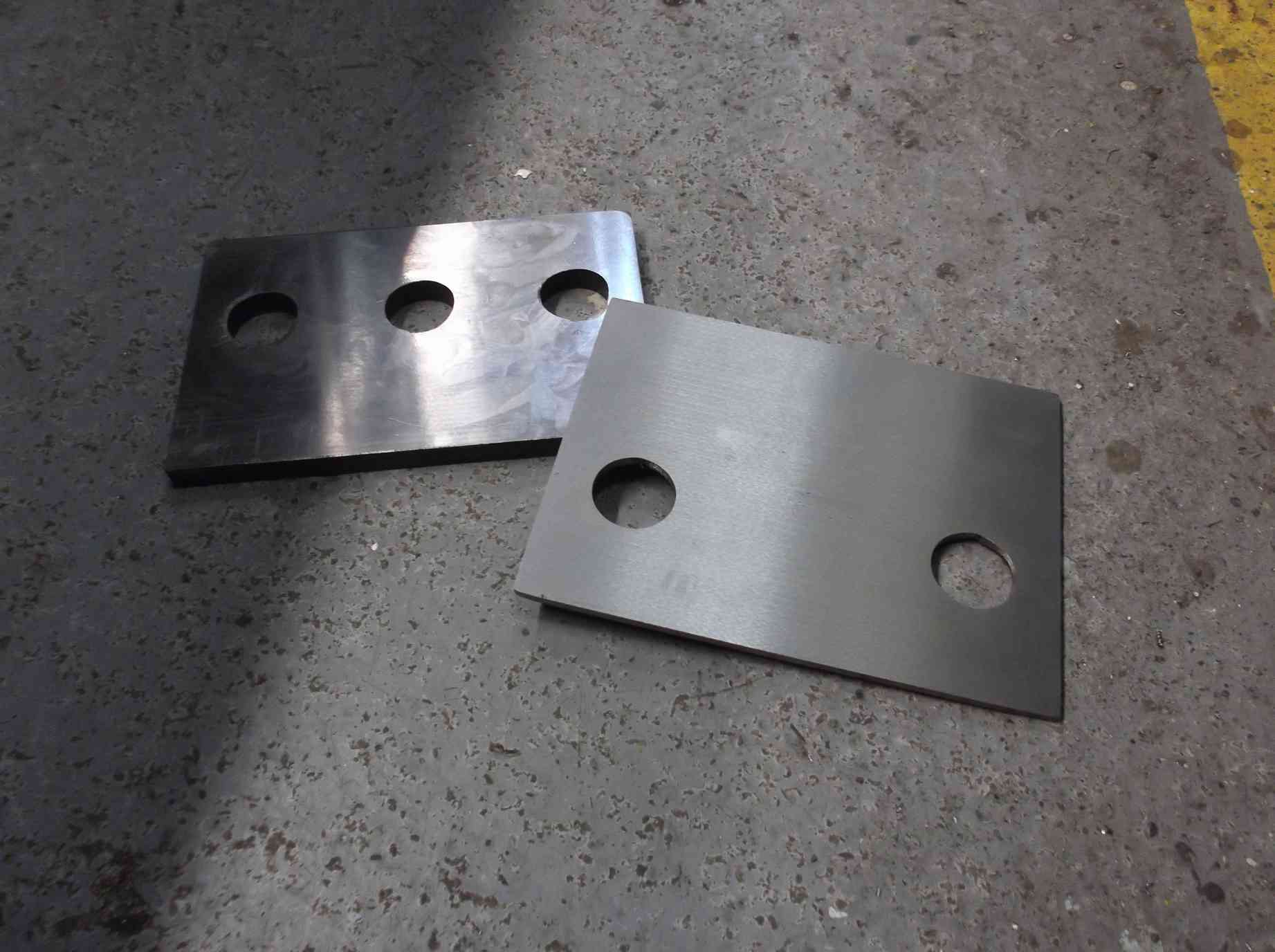
Work has progressed on the loco bogie side bearers. The left side was tacked up on the loco on Wednesday. The locating pins were then driven out and the assembly welded up on the bench. Meanwhile, the last hole in the right bearer was drilled through to final drill size. These plates have now been taken down and prepped for welding.
The corridor roof on the tender has seen the last replacement section against the coal division plate trimmed to size and fitted. Work on the corridor in the water filler space will be confined to patching as the plate here is in better condition.
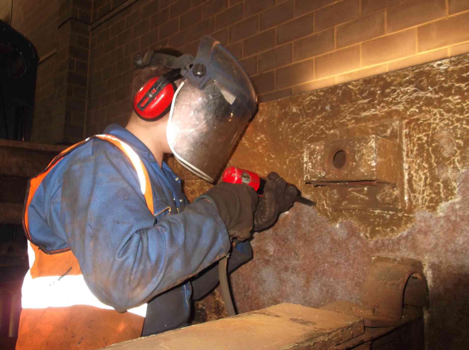
Much effort has been put into descaling and cleaning the bottom of the tank. The bottom plate forms the bottom of the tank and the foundation on which the tank is built. Now exposed, it will be thickness tested. The sump, which was replaced in the 1980s, seems sound, but toward the front of the tank and around the sides where the frame brackets are there are signs of corrosion.
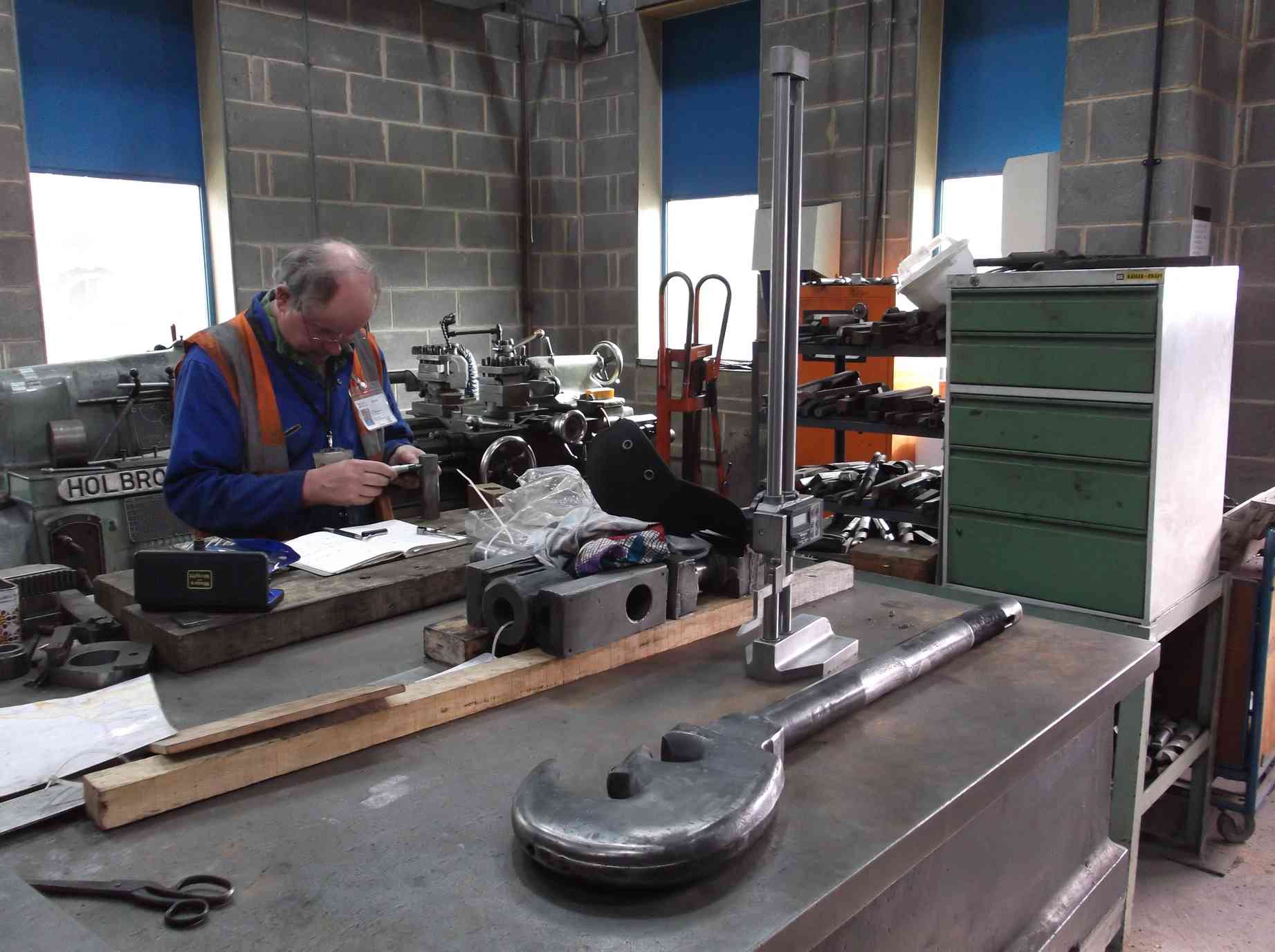
Measuring of the tender frames, axleboxes and wheelsets is ongoing under the guidance of our CME.
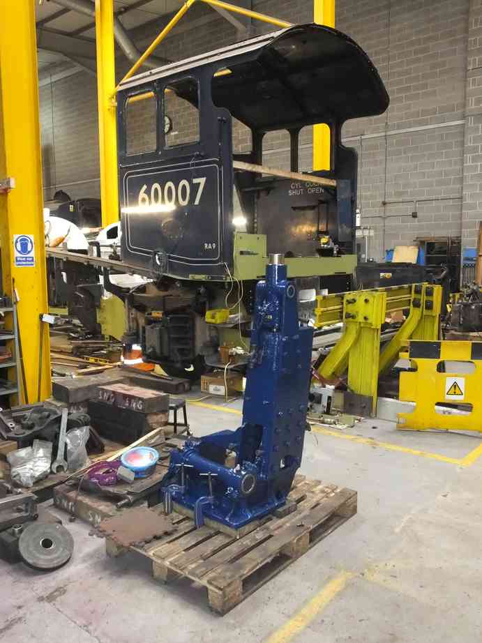
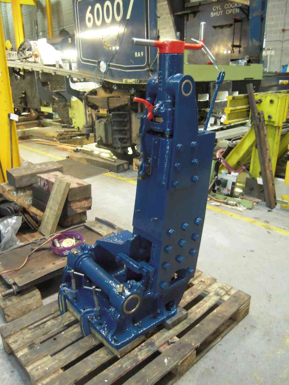
The reverser stand has now been painted to top coat gloss. A coat takes about half a day to apply, as much of it has to be done with a small brush to fit in around the screw shaft.
All the new thrusts have now been fitted to the axleboxes, and the first axlebox had been put up on the horizontal borer at Grosmont MPD. I went to Grosmont with our CME to confirm our instructions for the machining of the axleboxes. At the end of the meeting we were confident that the boxes will be machined to our requirements. It is expected that the driving boxes will be completed first, followed by the trailing pair.
Weeks commencing 20 and 27 August 2018
The air pump lubricator drive pneumatic cylinder has now been fitted to the lubricator and has been satisfactorily tested on compressed air. The end plates on the cylinder are now being finished to size.
Work continues on the tender with more needle-gunning and wire-brushing. This not only includes the frames but also the removed components. The spring gear is being methodically worked through, while the draw gear has been wire-brushed and the buckeye coupler cleaned.
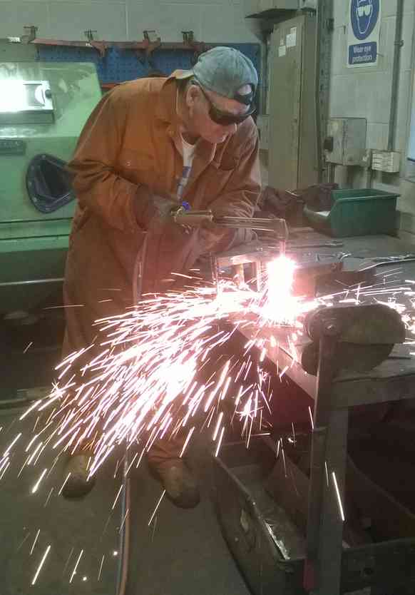
The vestibule support rods show much wear and it was decided to weld repair them rather than produce new ones. The areas requiring rebuilding were marked up and have now been welded.
The frames still require further needle-gunning. A number of 007 Gang members have come in on extra days during their summer holidays to put time in to needle-gunning the frames.
The tender corridor roof is completed, except for the short section at the cab end which will be left until the tender front is repaired. So attention has now turned to the water filler space. The air tanks and other air system components in this area were removed. The area then needed cleaning out. Further work is required in here to get down to the bare metal to find sound material from which we can start repairs.
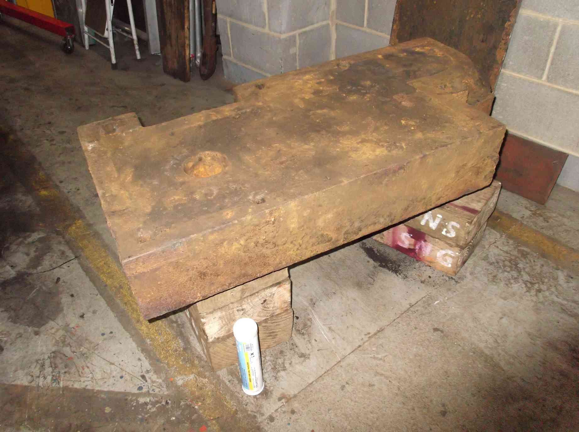
At the front of the tender the large cast iron weight that also forms the step into the corridor has now been removed. This exposes the tender front where it joins the bottom plate. The front of the tender can now be descaled and thickness tested.
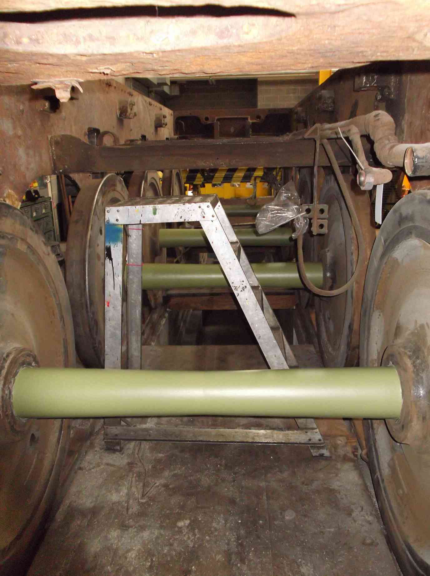
The tender wheelsets are being cleaned off and are now receiving their first coats of primer, and further work is being done to get down to sound material on the tender brake cylinder mounting brackets.
The reverser stand is effectively completed. The reverser lock hand lever has been fitted and the linkage connected. The final coats of paint have also been applied.
The last of the large studs used to secure the footplating to the slidebar brackets and cylinder castings was fitted this week.
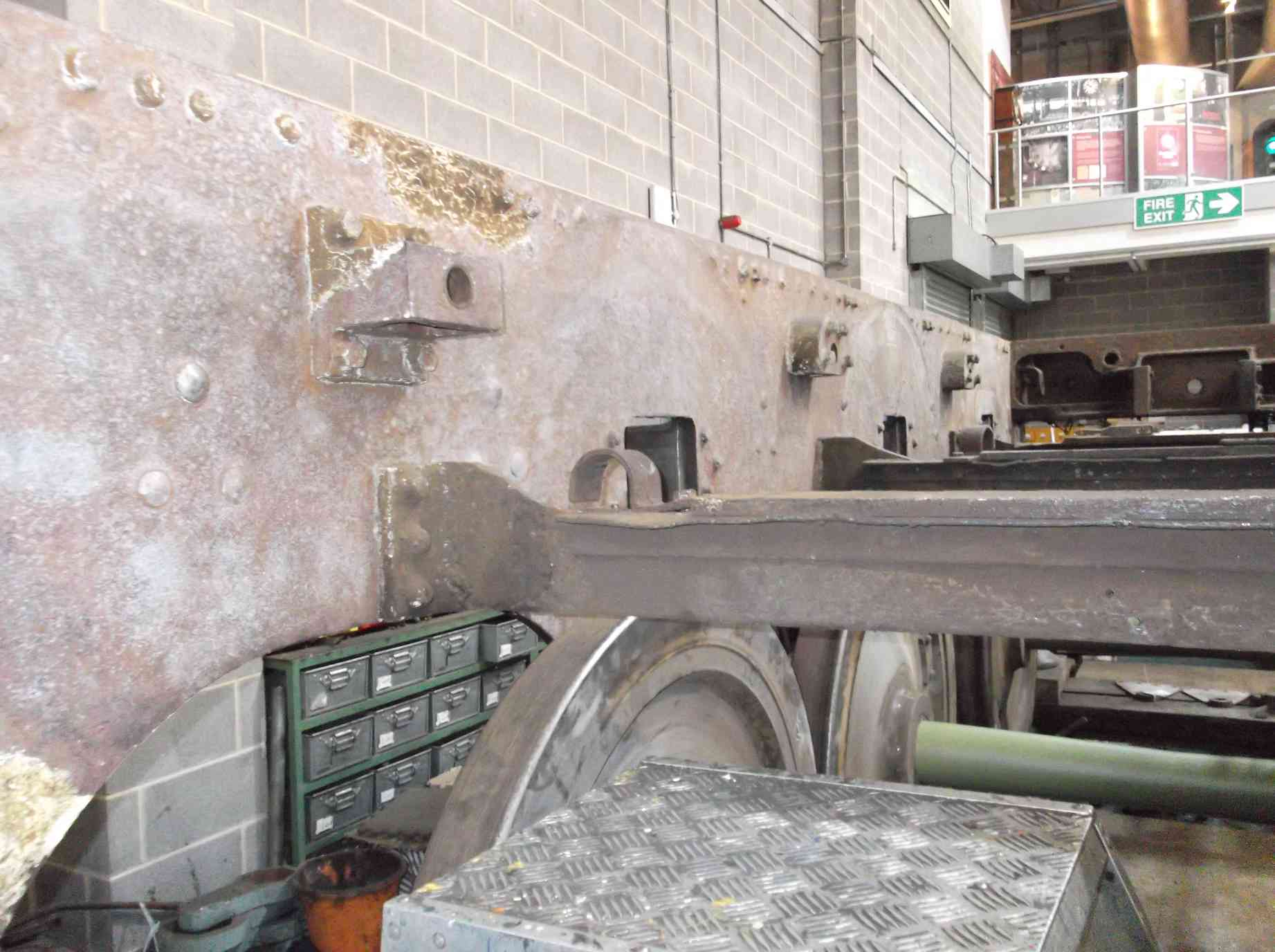
The loco bogie side bearer installation continued with prepping the right-hand plates for tacking. The plates were put back on the engine and clamped in position then tacked. The left and right have both now been welded. The side plates were then cut to shape. They have also now been machined to level them and been trial fitted to check their alignment. When pinned back in position they are tight against the bottom of the frames, and when checked with a spirit level are level with the loco bogie stretcher both across the loco and fore and aft. Exactly what we want.
The sealing and testing of the superheater header has been continued. For the higher pressure tests we now need to carry out, some of the rubber gaskets have been replaced it has now held pressure well in excess of 300psi. In fact a higher pressure gauge is now required. A date has now been fixed for its final pressure test when an inspector will be present to witness the test.
Re-piping around the frames where the ashpan is fitted is being continued. This has involved the redesign of the pipe runs down the left inside of the Cartazzi frames.
The work on measuring for new pins and bushes for the valve gear has continued. The expansion link trunion bearing covers have previously been straightened and the countersunk holes for the fixing screws tidied up. New screws have now been made and trial fitted. Each is specific to its location and had to be individually fitted.
The surface grinding of the slidebar shims has now been started, and the inspection of the conjugated valve gear.
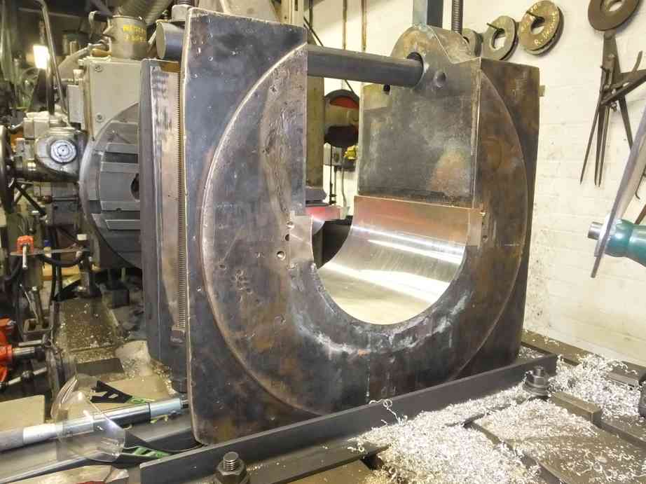
The driving axleboxes have now been finish-machined. It is planned to machine the trailing set next. In preparation for their return the spring hangers that are pinned to the bottom of the axleboxes have been retrieved from store. They had been cleaned and wire-brushed when removed from the loco. They have now been di-pen inspected. The bushes in the hangers will require replacement but first the hangers will require boring out to return the holes to round.
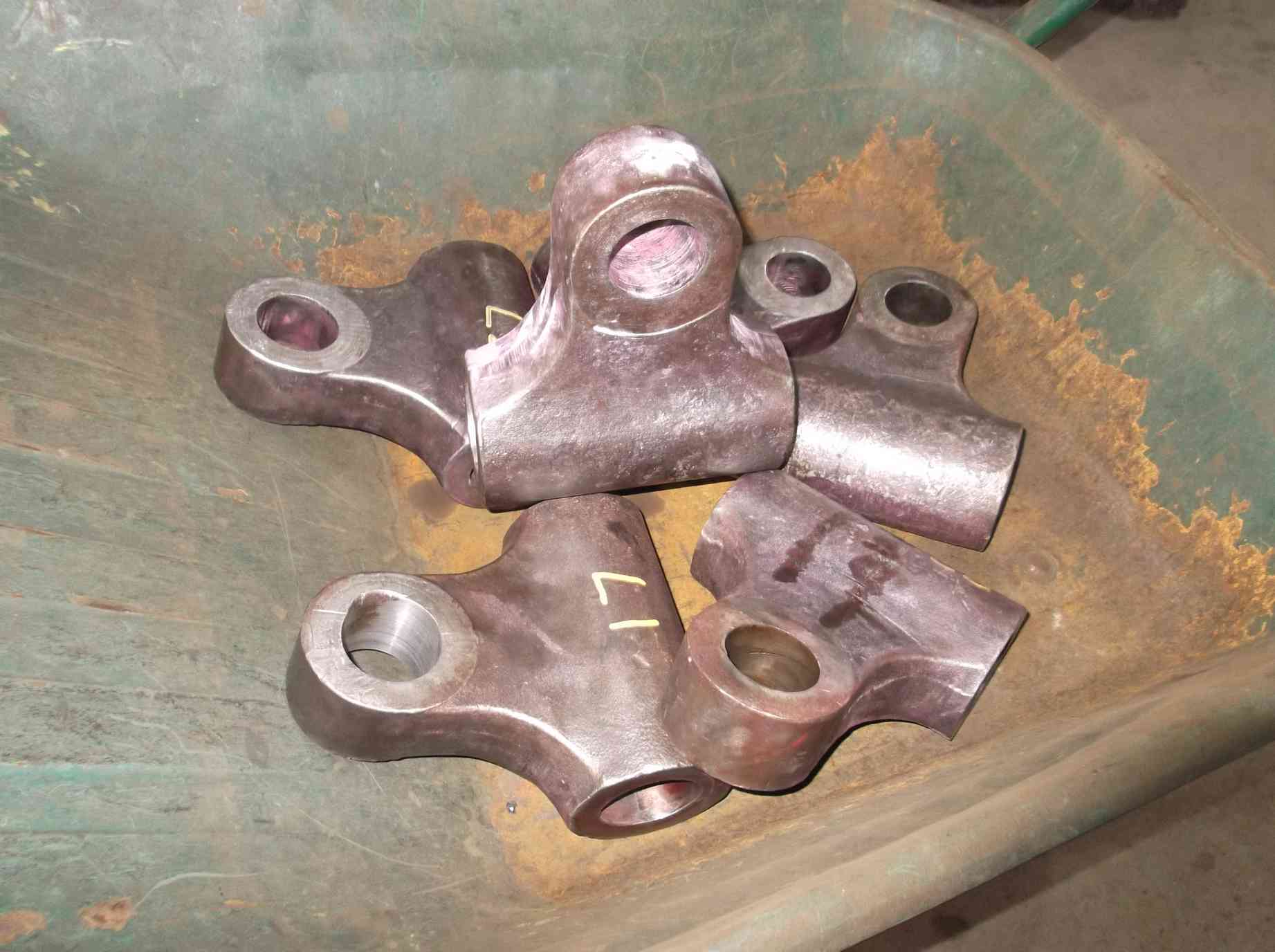
A sample has been done satisfactorily and the remaining five will now be treated similarly. Other work on the hangers will be the replacement of one of the large pins than goes through the hanger and bottom of the axlebox.
This is the 31st update—you can read all the previous instalments here.