Weeks commencing 4 June and 11 June 2018
The preparation for the pressure testing of the superheater header continues with making up new plate for the anti-vacuum valve connection and fitting the plugs to the superheater element holes.
The new slidebar shim material has arrived and has been prepared. The profiling to fit around the shape of the outside sidebar brackets is very good. Now the shims are deburred, they can be put on the surface grinder and finished accurately to size to replace the stacks of shim used in the setting up of the bars.
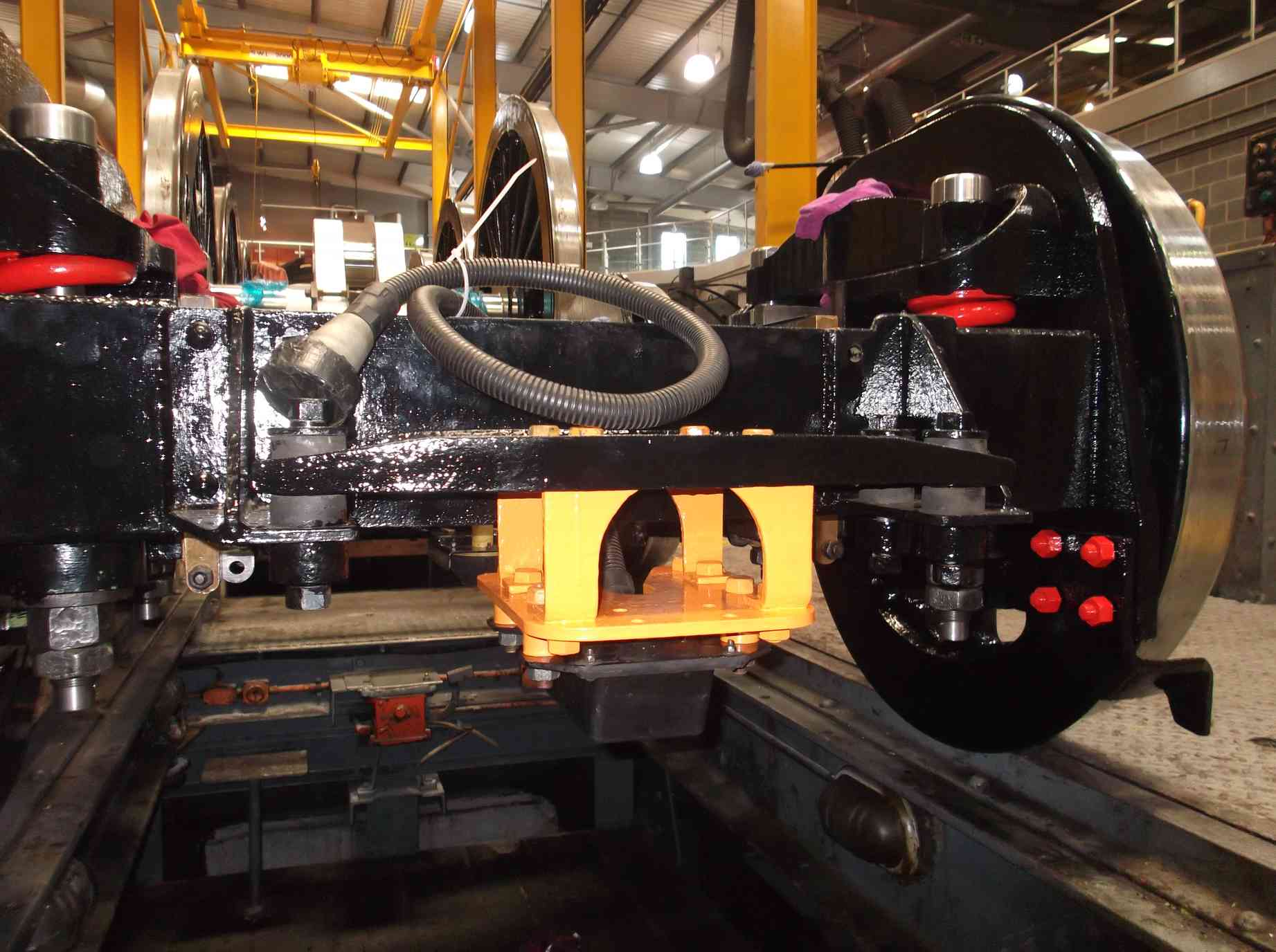
The AWS brackets on the front of the bogie are mounted on anti-vibration rubber bushes. Rail spare part stockists have been contacted for replacements and even though the same arrangement is fitted to some diesel locomotives, they say there are no spares available. So, new bushes are being manufactured by the rubber manufacturer we have used for some other parts on the locomotive. The TPWS bracket and aerial and the AWS receiver and carrier have now been fitted and new grease nipples fitted to the side bearers.
All the bogie spring hanger bolts have now been drilled for their split pins, and while out the spring beams were adjusted to ensure when the bolts are fully loaded by tightening the bottom nut, they don’t spin. The bolts have a flat that locates against a face in the beam which is supposed to prevent this. The faces were repaired, so we shouldn’t see a repeat of the difficulties we had when trying to remove the old bolts.
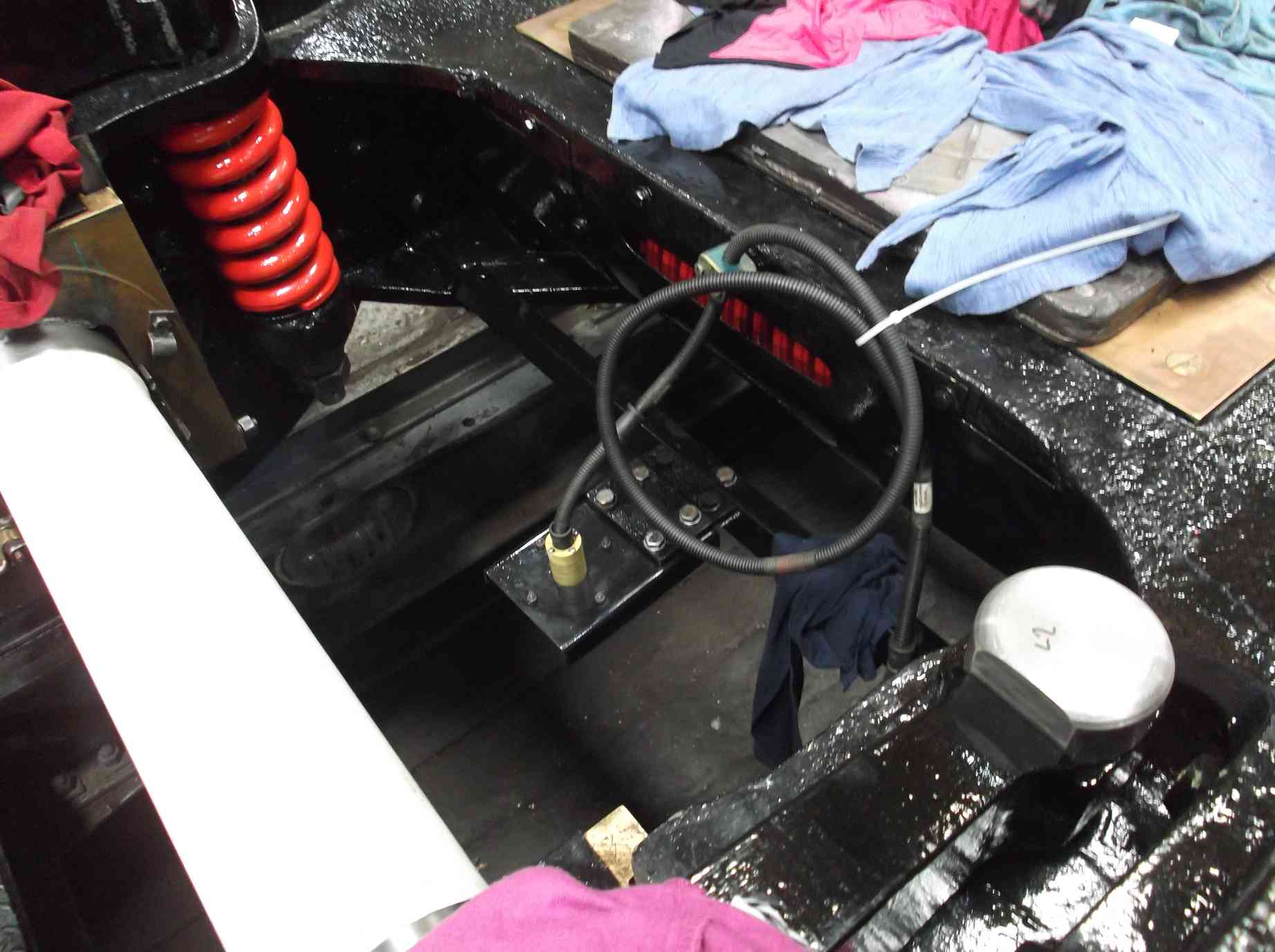
The reconfiguration of the air braking system is being progressed by the volunteer Piping Team. The team has done really well in recovering pipe and fittings but now we are looking and purchasing new. They are currently working on listing what we will need to complete the job. With the leading oil boxes mounted on the footplating the lubrication piping in this area has been inspected and annealed to prepare it for fitting.
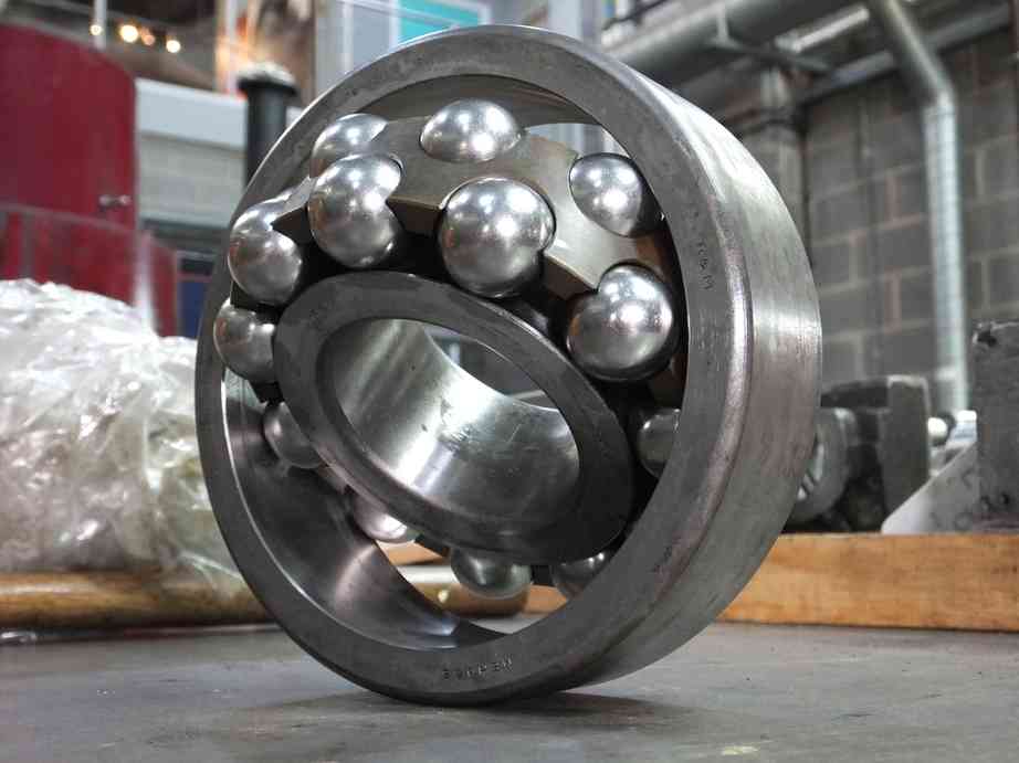
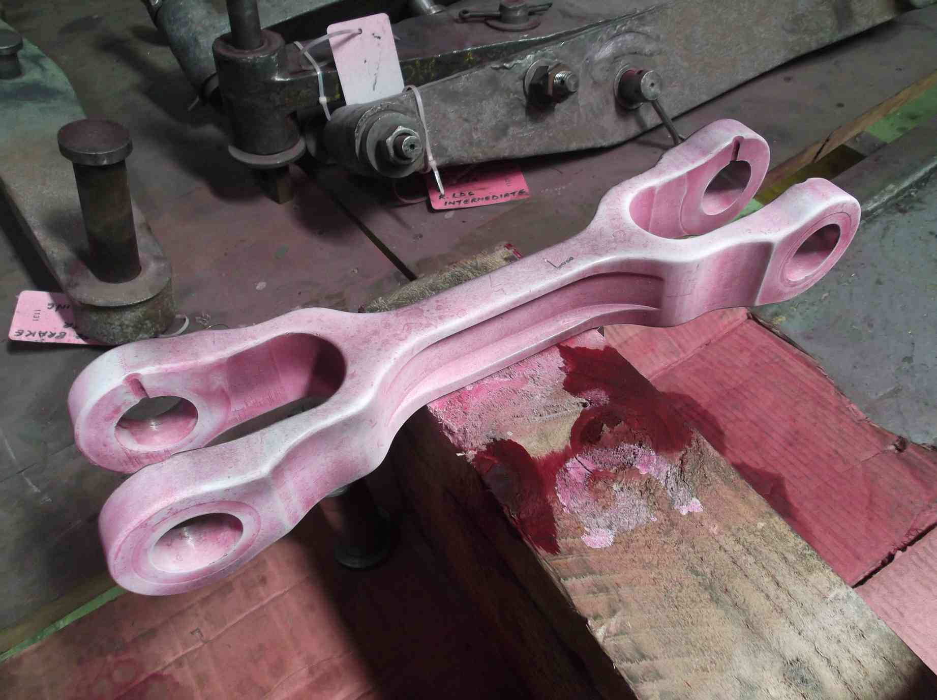
Work continues on the outside valve gear and associated components with the rods receiving careful final cleaning. This has included the combination levers and union links. The rods have also been dressed to remove the sharp corners and dents and scratches the loco picks up. The return cranks have been removed from the crank rods and the spherical bearings removed and inspected. One of the bearings, most probably from BR use, has been found to require replacement. However, these bearings are of a size unavailable as a standard catalogue item so we are investigating ways of replacing.
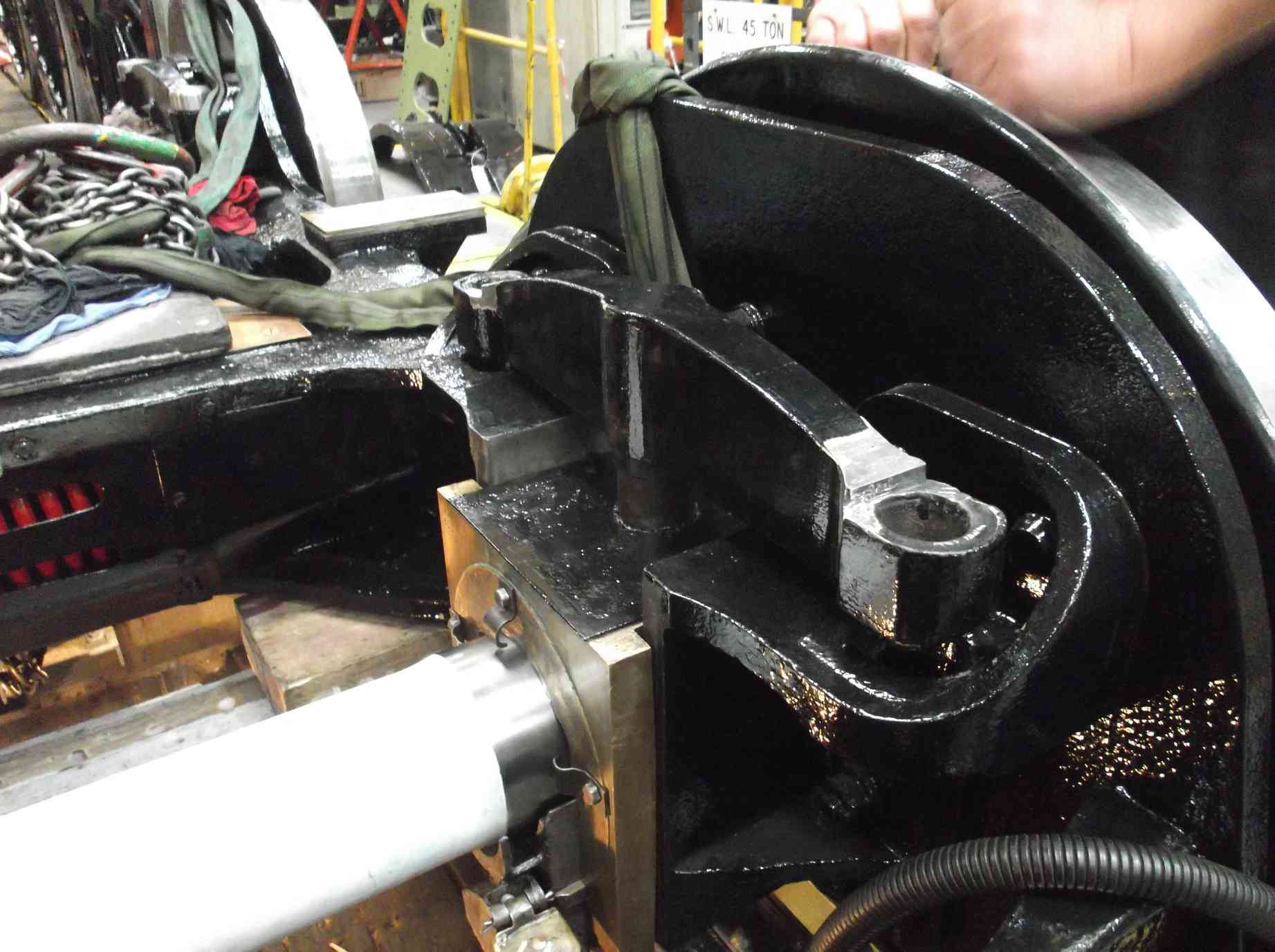
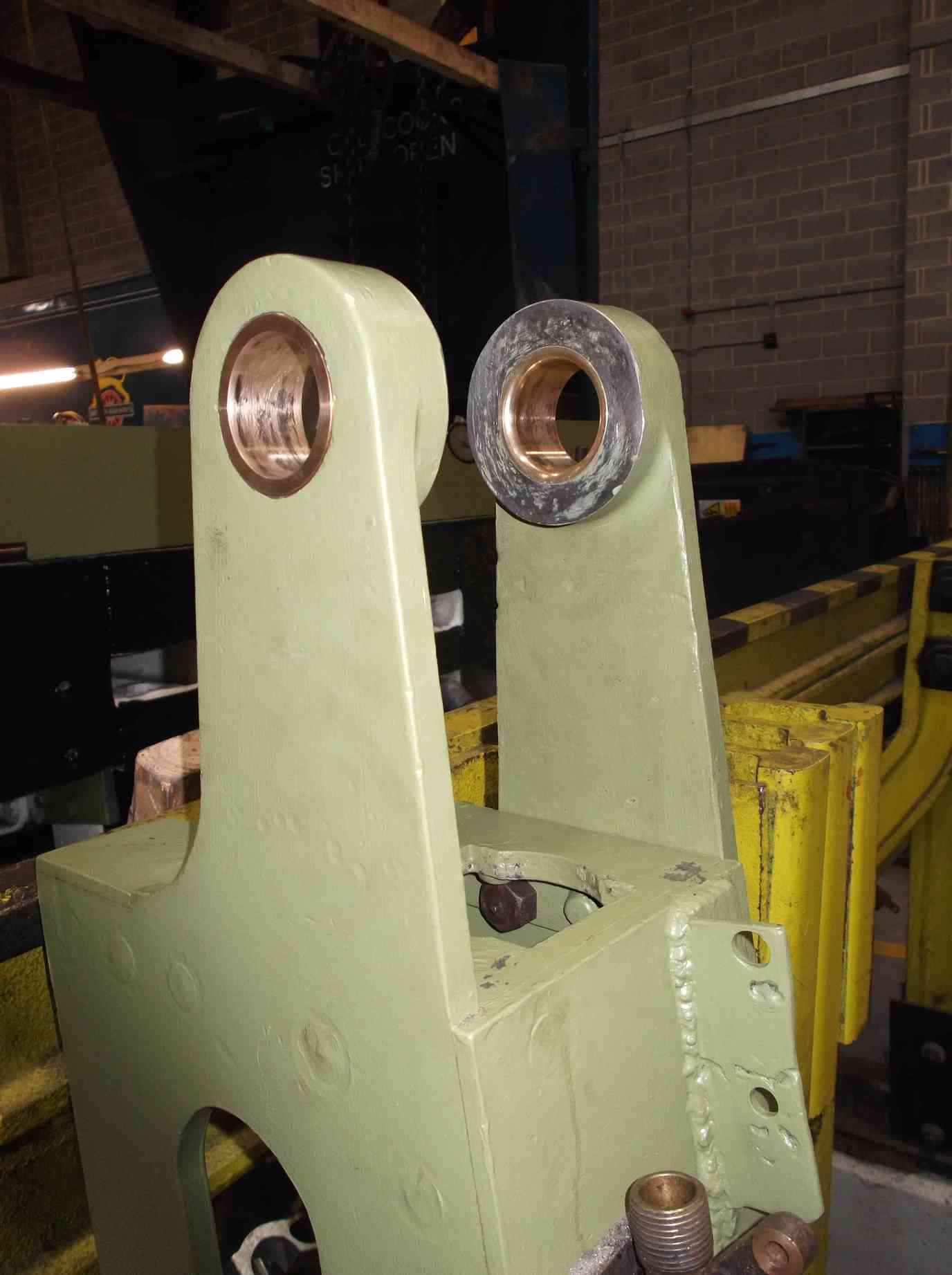
The inspection of the expansion link trunnion bearing housings has shown that there have been historical repairs to the locomotive. At some time the housings, part of the brackets on the loco, have been re-bored and lined. Unfortunately they have not been bored on the original centre line, resulting in an offset liner in the bracket hole. We can only imagine that at some time the bearings have seized and damaged the housings requiring them to be repaired in this way.
The off-centre repair has resulted in the rear cover plates not fitting accurately as they follow the original hole centre, and the right has been slightly deformed. The plate has now been heated and reformed so it is flat and the housings carefully dressed to allow the correct fitting of the plate. The inner plates are bronze as they fit between the bearings and the sides of the expansion links. These were found to be cracked. These have now been silver soldered and will require machining. Another job expected to be a strip down, clean and refitting turns in to a team effort with a series of defects requiring rectification.
The inspection of the outside trailing valve covers is complete. The left was defect-free, though the rougher looking of the two, but the right will require some repair work.
The damper linkage is now being refurbished. The damper reach rod has a forked end (clevis) which was heavily worn so a new end has been fabricated. The damper is on the front of the ashpan and the rod is part of the linkage that runs from the cab. Both the linkage and ashpan are required in position so that we can see how much room there is available for the pipe runs, so with the ashpan repairs completed, the ashpan has now been trial fitted.
The last of our repair work to the ashpan has now been completed. An additional pin has been fitted to secure the ashpan spark screen and a new pin for the damper operating reach rod. As the platework on the ashpan is now complete the boilermakers have now started putting in the new tender corridor roof plates, with the first piece now tacked in place. Also from the tender the brake gear is now being cleaned and stripped of paint prior to inspection.
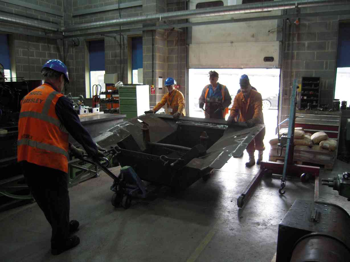
To fit the ashpan, the cab has to be removed and placed to the rear of the frames. It’s a tight squeeze and moving the ashpan around on hand trolleys was a delicate operation, requiring good teamwork. It took all day to move the ashpan in to position. When lifted in, surprise, surprise, it did not want to fit. However, a couple of the Engineering Team volunteers have been left with the job of getting it into it’s final position and they are progressing well.
The broken stud in the right cylinder flange was removed by drilling through its centre, and when we attempted to tap it out it gave up and screwed out. I was particularly proud of how accurately I’d drilled through it’s centre when it was at the bottom of a 6″ deep hole in a top corner under the engine, however nobody else on the Engineering Team seemed that impressed. I was just told how many others had drilled bolts out all they were left with was a helix of thread. Where the stud had failed the saddle casting required easing so that a straight stud will fit without fouling the saddle.
The horizontal hornstay bolt holes are now complete with the countersinking finished. The new bolts are in stock, all sponsored through the pages of our Chime magazine. They will be machined to suit individual holes but will not be fitted until the wheels go in, so they will not be required to be removed, and refitted.
The thrust insert material for the coupled wheel axleboxes has now been cast and has been dispatched from the foundry. We await delivery.
The rebuild of the reverser stand continues with the alignment of the bearings for the trunions of the reverser screw nut housing. This has required the scraping in of the new bearing and the realignment of the bearing housing.
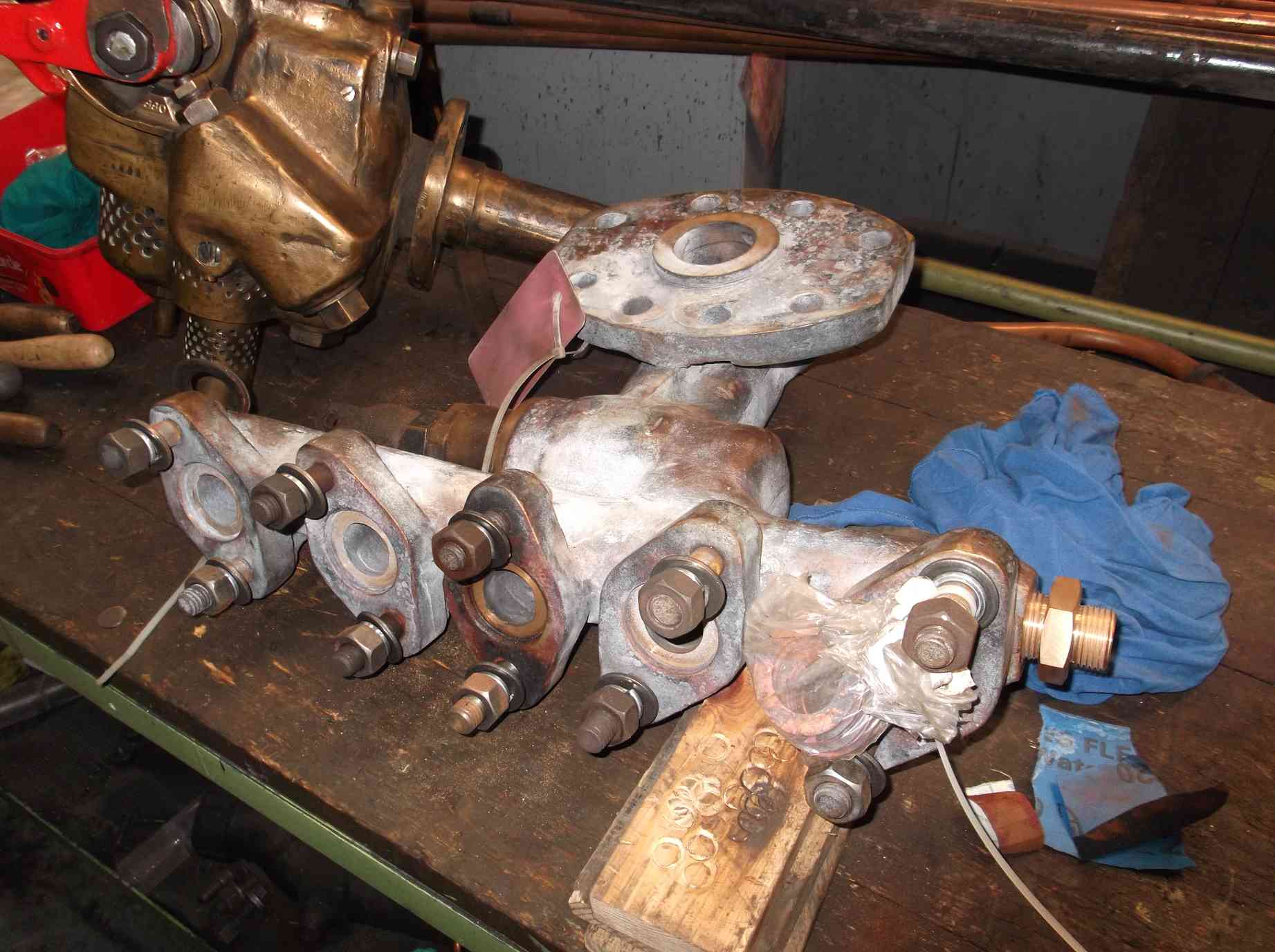
The steam heat valve from the boiler manifold has been returned from contractor repair. This valve required a new body, cast in bronze. As many parts of the old valve as possible have been used. The sealing copper rings for the valves mounted on the manifold have been annealed and the end fitting, also new and made from bronze is being fitted. The clackboxes have now been delivered to Llangollen.
The new piston was fitted to the change over valve in the air pump this week. The pump was then trial run and worked, reversing the power stroke down to low pressures only previously possible with soft packing in the old piston.
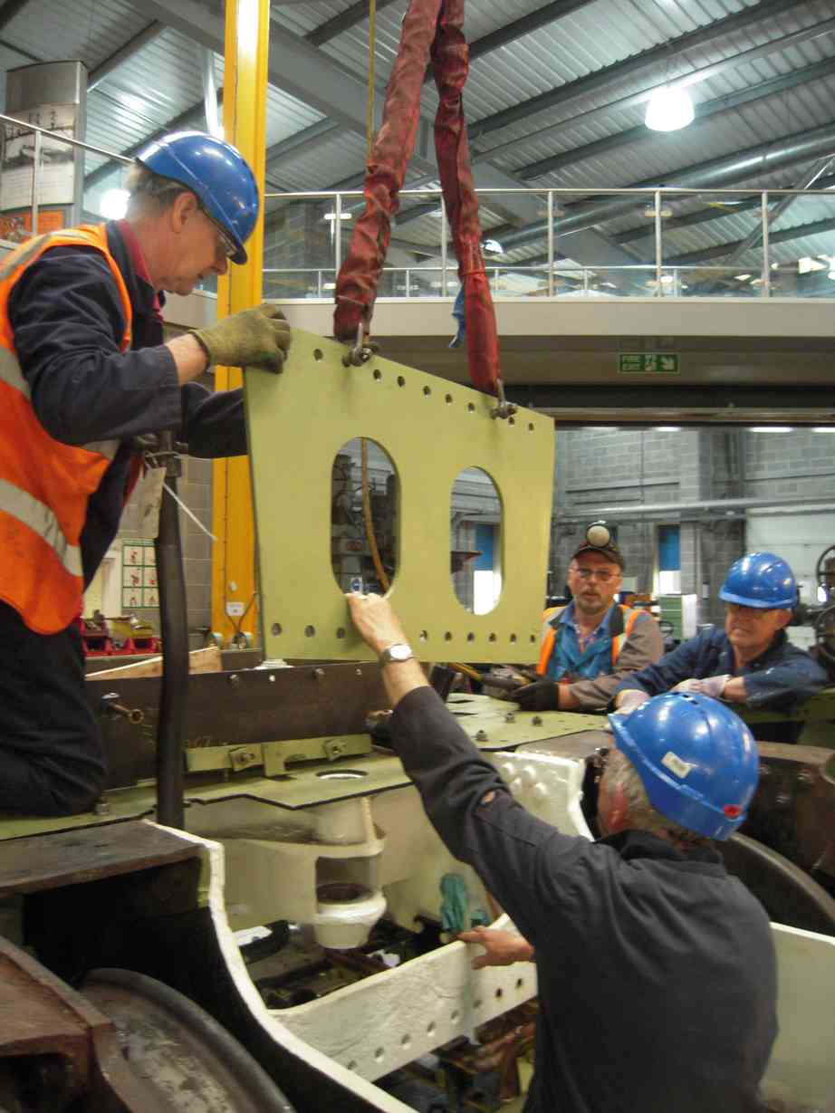
At Llangollen the regulator is now being finally fitted. New bolting has been manufactured for the regulator to main steam pipe clamp and the hanger bolts made by the volunteer Engineering Team at York are being fitted. These are used to accurately position the valve from the boiler. It is not now possible to access the boiler from the dome, so only individuals of slight stature can access through the belly door. A bit of a problem as most boilersmiths I know can’t really be called slight.
Week commencing 18 June
The footplating along the sides of the loco are held down outboard by the cylinders and slidebar brackets, which have all seen considerable wear over time. The holes are now of various sizes and have broken studs and incomplete threads, so we decided to repair them. These are important fastenings as they hold the outside of the footplating down. For the last couple of weeks the Engineering Team has been going round them and drilling the holes out so that stepped studs or repair bushes and plugs can be fitted.
Good progress has been made on the clean up and paint removal of the tender brake gear before full examination. The 1928 beading removed from the top of the corridor had left a series of holes—not good for keeping the rain out—so these were plugged with countersunk rivets that have been seal welded in.
Work continues on the fitting of the ashpan in the correct place in the frames. We will only know for certain where it should fit when attached to the boiler, but by examining photographs we know it should be forward of the location it initially went into the frames. Some adjustment of the damper door hinges was required and this has been carried out. This also required the removal of the damper door and some trimming of its bottom edge.
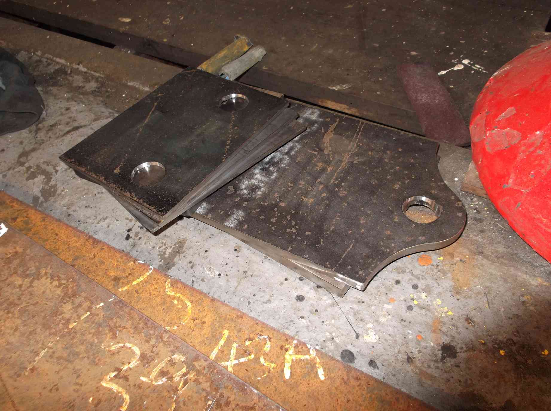
The loco bogie sidebearers were worked on this week with some of the profiled plates cut and shaped to get the size required for the fabricated bearers.
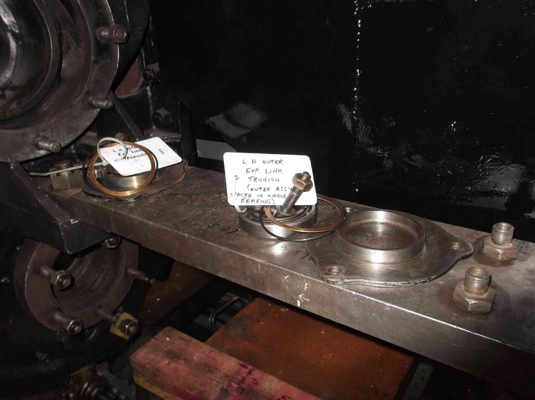
Work continues on the valve gear components with dye-pen examination of the return cranks and combination levers. No faults were found. The expansion link trunnion bearing housings were dressed last week, and this week the bearing assemblies were trial fitted. There is some wear, as the bearings are not as tight as they should be, but we think using a proprietary bearing housing sealant should solve that. Fitting the inner covers does show that some of the screws, which look very old, really don’t have enough left of their heads to be reliable, so new screws will be made.
The expansion link trunnions are bushed. A couple of these were loose and will have to be replaced, and the tight ones could be a better fit on the bearings, so we have decided to replace all the bushes. One of the tight ones was removed and revealed damage to the trunnion that will have to be repaired.
As mentioned in the previous report, one of the return crank bearings requires replacement. As it’s a non-standard item according to current catalogues, we have been investigating ways of getting a new standard size bearing to fit. We have talked to other loco owners and they described how they have made spacing arrangements to fit a standard modern bearing. However, our CME has found an exact replacement, though we have been warned that it has been sat on a shelf for a long time, perhaps a very long time. Hopefully it will be free of corrosion and suitable for use.
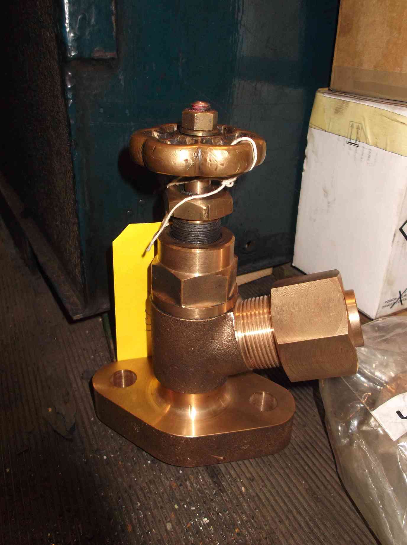
The new end fitting that the steam sands shut off valve is connected to was fitted to the manifold this week. Its face was scraped until a good fit was achieved onto the manifold. Fitting without a copper washer in this location should give us the best chance of a reliable long-term joint while allowing the valve to be tightened and positioned to where we need it to point. The plug at the opposite end of the manifold was also fitted.
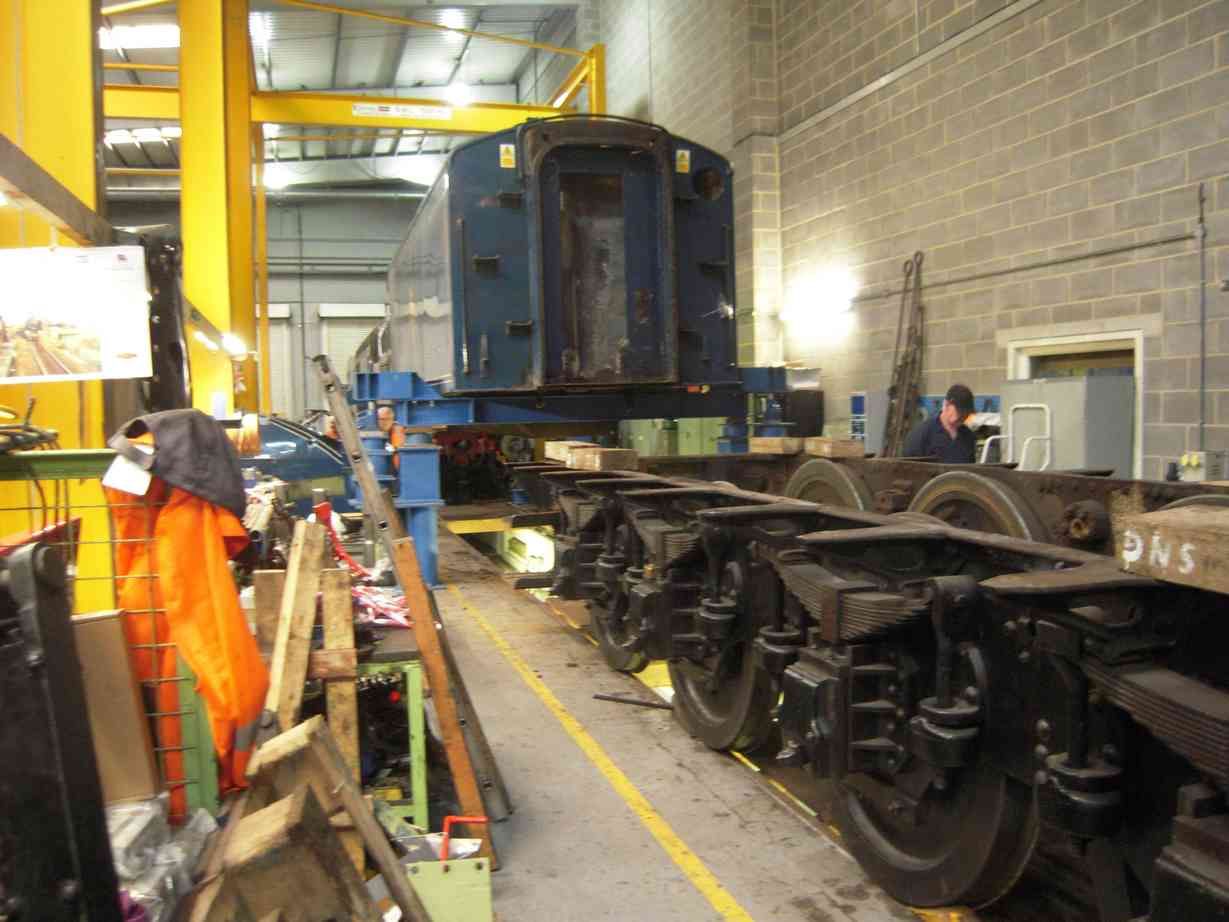
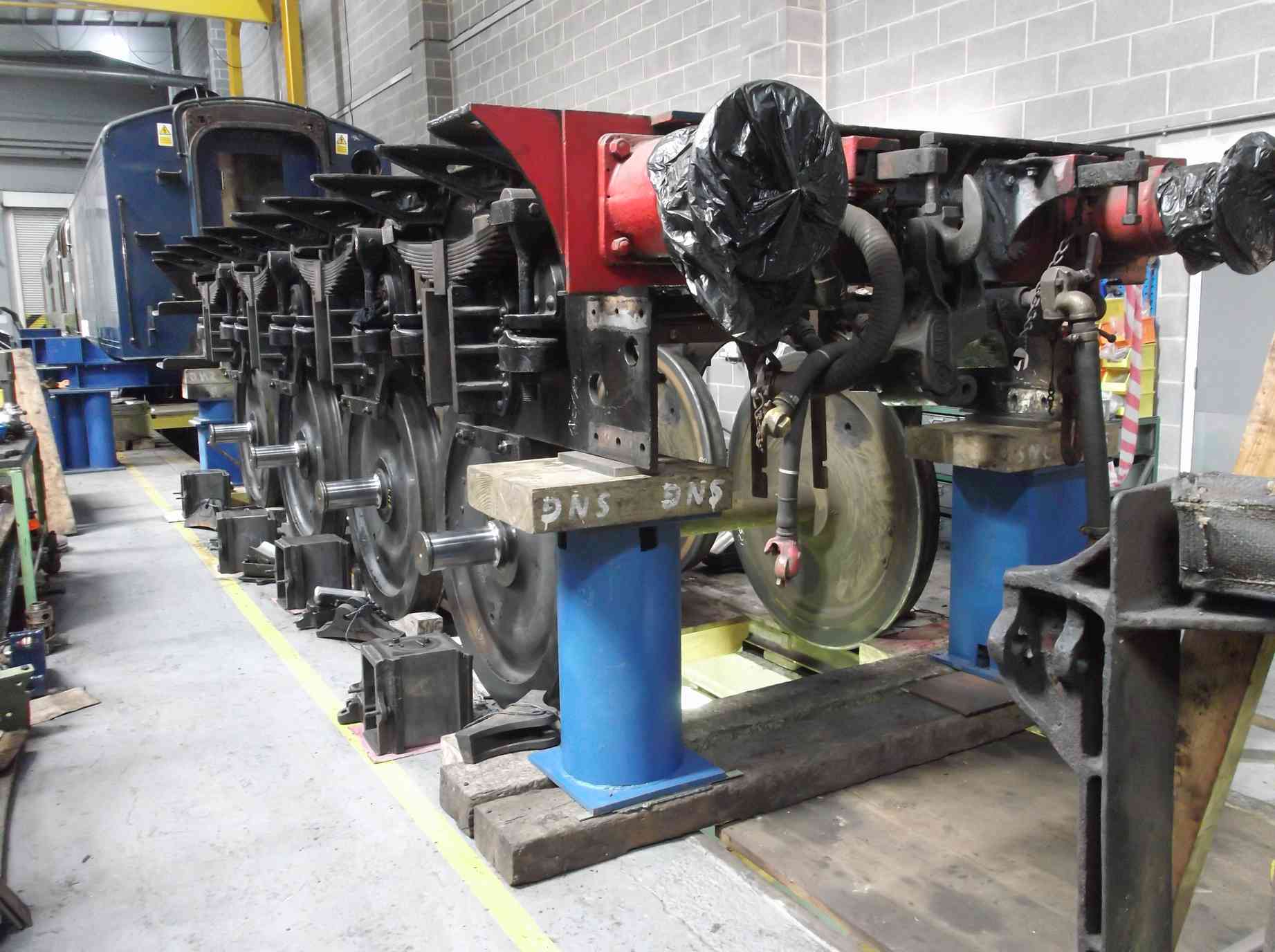
The driving wheelset was removed from the workshop this week and this provides us with much more space around the front of the loco. This will facilitate the planned tender tank lift. Plans for the lift are going well, with the delivery date of the equipment now finalised.
Progress toward the final completion of the coupled axleboxes has been made with the delivery of the axlebox thrust material. The 12 thrust blanks are now waiting their turn on the milling machine before fitting to the axleboxes. This is a subcontractor job and all the documentation required has been generated, checked by our CME and sent to the subcontractor.
The new rubber for the spring behind the front drawhook has finally been collected from the suppliers. Normally a one week delivery time, we’ve been waiting for this since May.
Weeks commencing 25 June and 2 July
The two studs for the right cylinder, frame and saddle joint were machined and one is now fitted. Again the faces of the saddle casting require careful preparation to get the seat of the nut square to the centre of the stud, so that the stud has a straight pull on it without being bent (a probable cause of the previous failures with these fasteners).
On the subject of studs, the repair of the footplate studs in the cylinder castings is progressing, with material now being machined by to produce the studs. Each is having to be machined specifically for its location. A couple of the existing holes in the slidebar brackets have been plugged and will be drilled and tapped to return them to the original thread size.
I went to collect the new rubber bushes for the bogie AWS bracket, but they have been made from the wrong thickness of material and were rejected. On the positive side, progress has been made with the first two of the loco bogie sidebearer bushes. These have now been machined and the plates for the side bearer fabrications are being shaped.
The new rubbers for the front coupling hook have been checked over and all is to drawing, so now a jig for the assembly of the rubber springs has been designed.
The overhaul of the reverser stand continues with the reverser nut thrust bearing being replaced. To replace the old bearing the new bearing races were surface ground so that its overall thickness is now the same as the original bearing.
In preparation for the tender lift and frame overhaul, the underkeep oil trays were removed and emptied, as were the underkeep oiler pads. The split pins from the hornstays were also removed. The tender frame guard irons and footsteps were removed from the rear of the frames as we will need to jack there. The last of the pipework that could cause issues during the lift of the tender frames were removed and the components tagged and noted on our schematic. The coupled wheels and bogie were moved as far forward as possible, so that as we have as much space as possible for the use of the workshop overhead crane when moving the heavy lifting equipment. The tender was then moved forward to the position where it was planned to leave the tender tank on stands.
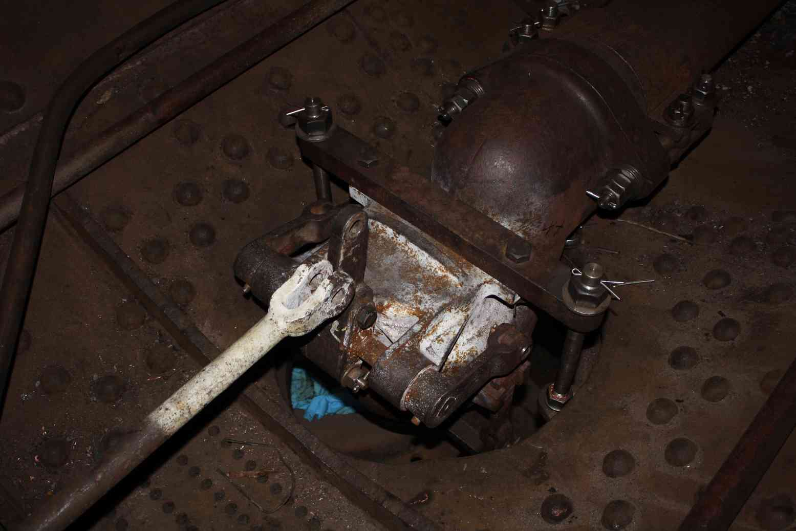
Elsewhere, we are steadily working on cleaning and needle-gunning the tender brakegear.
Little progress has been made with the valve gear over the last two weeks due to manpower being directed to other jobs, but we have managed to find time to di-pen inspect the union links.
Our coach is at CTMS at Cranmore for overhaul work and I visited it at the end of week 26. With the CTMS management we went through the original list of works so that both SNG and CTMS are clear of the work we want completed on our coach. The standard of the finish they achieve is very good, as displayed by an eastern region 1950s suburban coach standing in the sun outside their works. We have agreed to some minor amendments to the original planned works, so CTMS will requote and an amended purchase order will be issued. Work is scheduled to begin in earnest during autumn—our coach will be under cover from then until completion, planned for spring next year.
At Llangollen, the regulator is finally fitted and the positioning of the regulator reach rod has been measured and is at least two inches clear of the transverse stays. The new throatplate section is clamped in place on the foundation ring and is prepped for welding in.
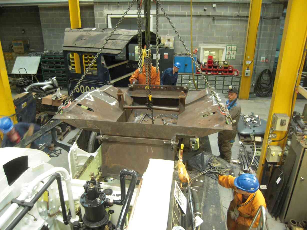
Most of our time during week 27 has been spent on lifting and separating the tender tank and frames. This has required a program of preparation over many weeks, including removal of numerous seized bolts holding the tank down and also pipework and electrical systems.
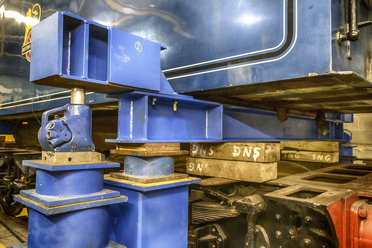
Away from the tools there has been a considerable amount of preparation, with valuable input received from our Team Leaders. As a result of this effort a risk assessment was completed and after discussions with lifting contractors we devised a procedure. We must thank Paul Gardiner of Durham Lifting for being so generous with his time. Paul planned the lift and supplied all the equipment that would be required, only requiring us to find a few shim plates and use some of our sleeper ends on the day. When the date was firming up for the delivery of the equipment, a roster was drawn up and the volunteer Engineering Team rallied to fill it. We were able to devise a plan for the week which allowed us to accomplish everything we wanted, while being unhurried within our normal working hours.
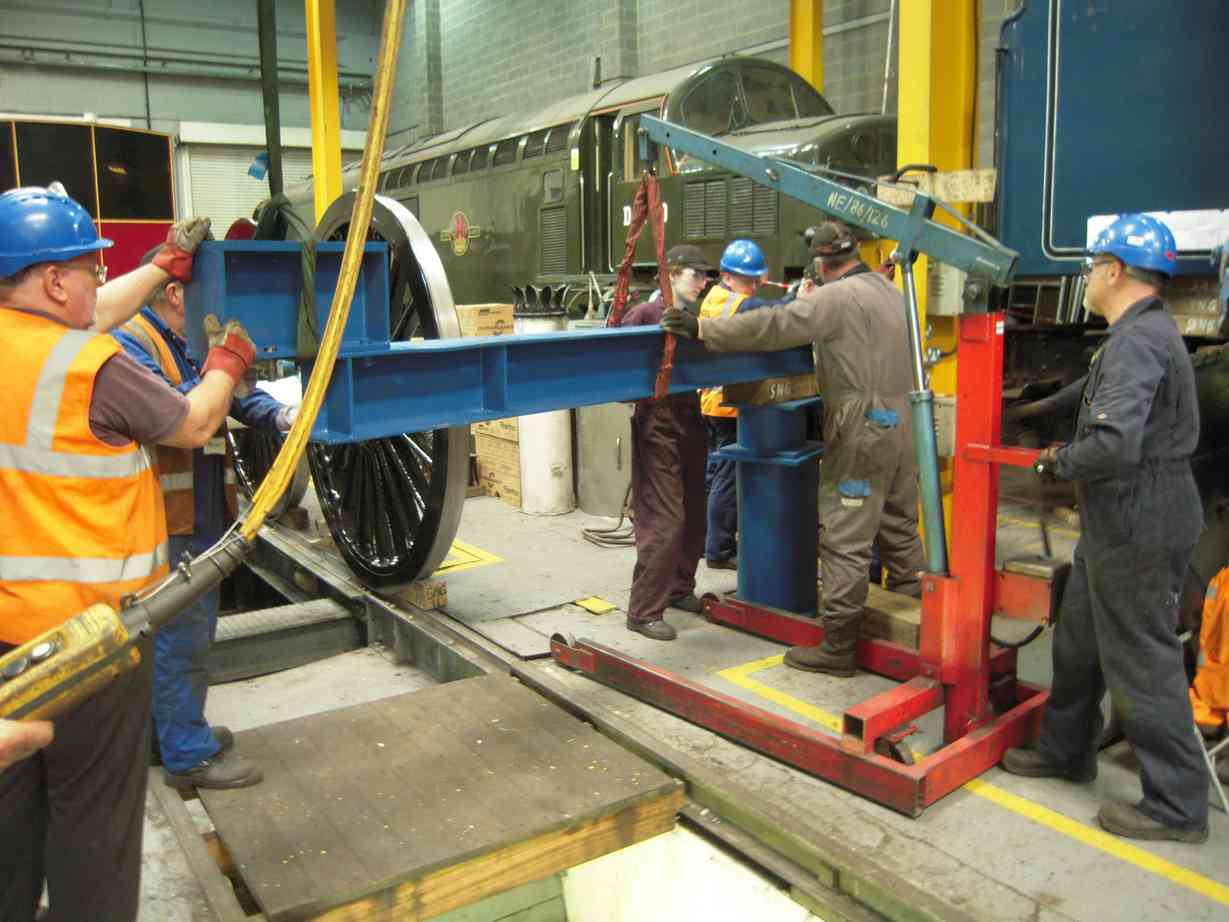
With the arrival of the lifting gear due and the Lift Team in the workshop, we had an initial talk though of the procedures and plan for the week. The equipment was delivered later that morning and we were helped by National Railway Museum workshop staff, who drove the forklift truck. Some of the lifting gear was very substantial, with the tender tank beams weighing 400kg each.
With the lifting equipment on the ground, the Lift Team moved it into the workshop. The base stands or stools were moved to the four corners of the tender and the rest of the gear unpacked and divided up. The whole operation was under the direction of the Lift Team Leader, who lead the operation until completion three days later.
With the corner base stools in place, jacking of the tender tank began. In each corner a team operated a hydraulic jack and manipulated packing, as many pieces would be too heavy for a single person to lift. The Lift Team Leader would not be operating a jack as he was required to coordinate what was happening in the four corners, and to check how the tank was responding overall to the lift.
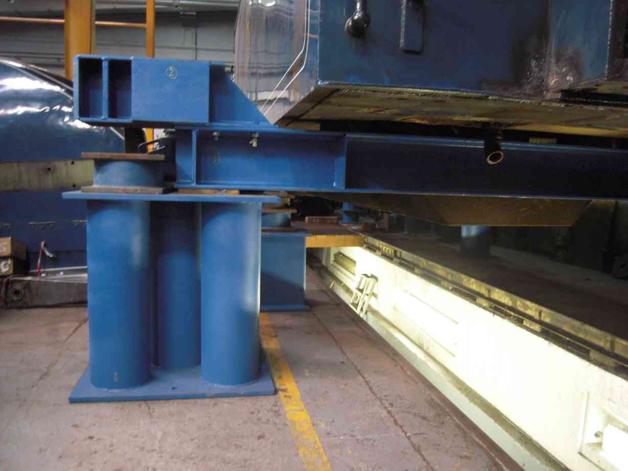
After each lift of approximately 20–25mm the tank was repacked so that in the advent of a jack failure, the drop would be no more than this. The tank is raised slowly with these little steps, slowly but safely. When the tank was raised sufficiently to allow the lifting beams to be inserted across the top of the frames and under the tank, packing between the frames and tank was put in. With this packing in, the jacks could be removed, giving clearance to put the beams in and to reposition the base stools outside of the tank so that eventually the frames would be cleared for rolling out.

The beams are very heavy and so were moved on the workshop overhead crane into the space in front of the locomotive. The crane doesn’t have the reach to support the beams until they are on the frames, so stools were positioned to give the beams a platform to rest on at frame height. Engine hoists, small mobile hydraulic cranes, were used to ‘walk’ the beams across the stools towards the frames. Eventually, with their weight supported on the frames, they were pushed into position by the Lift Team members.
With the beams in place, extension pieces were fastened to their ends, which allows the jacks to be positioned for the next stage of the lift. As before, small lifts were followed by packing step by step until the bottom of the tender tank and the vacuum cylinders could be seen to clear the frames. A chain was then placed round the tender drawhook and the frames carefully pulled from under the tank. When the frames were clear they were chocked and we treated ourselves to a brief pause for photos. Well, it’s not often you see a tender tank that high in the air.
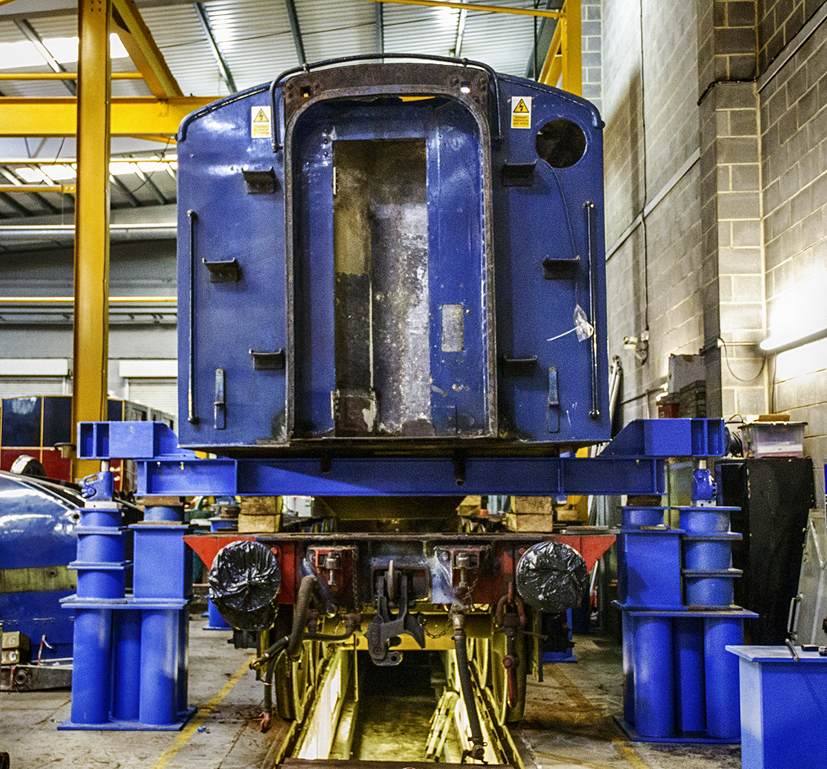
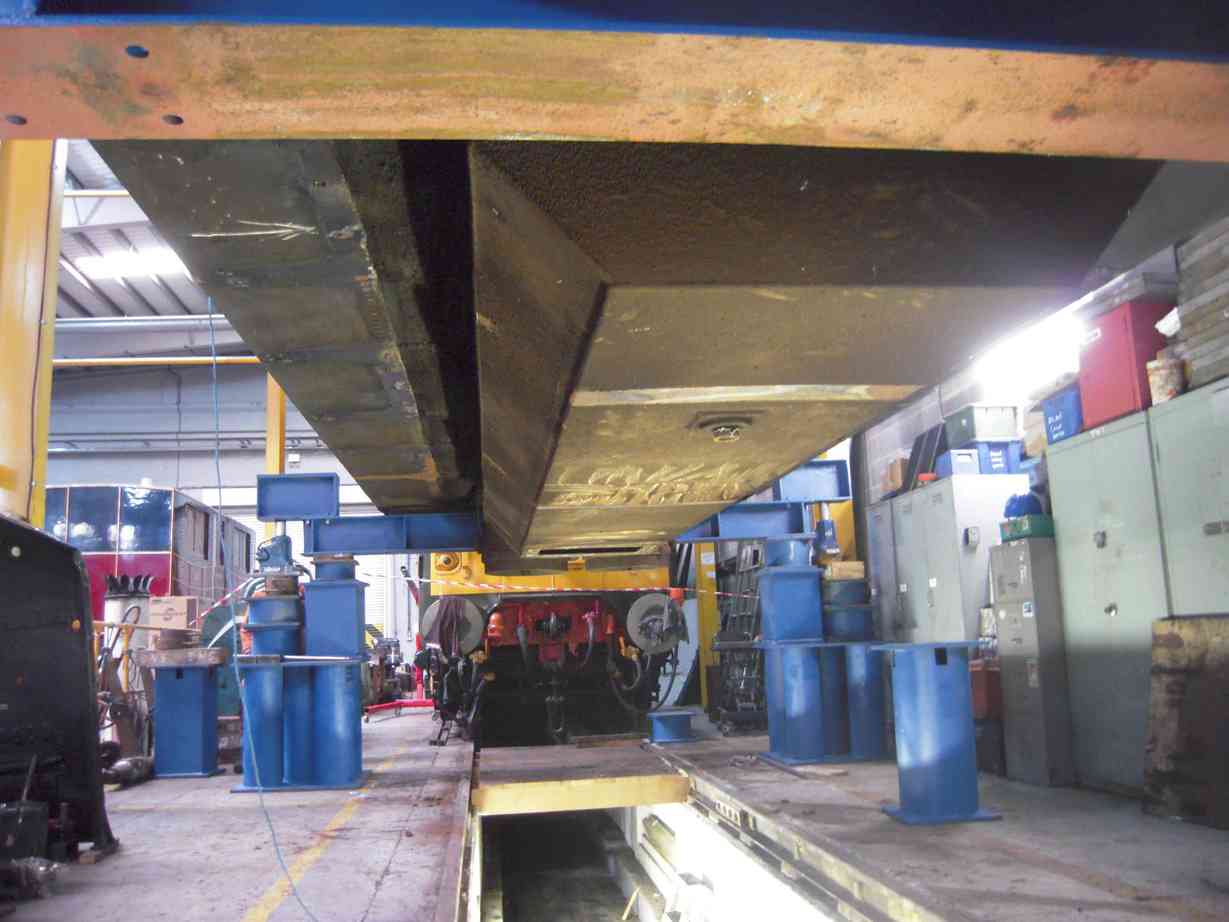
The tank was then lowered by removing packing, again in 20–25mm steps, paying careful attention to keep all the jacks loaded and maintain the level of the tank. Eventually the tank was left on the beams on the large base stools, where it will remain until it can be put back on the frames.
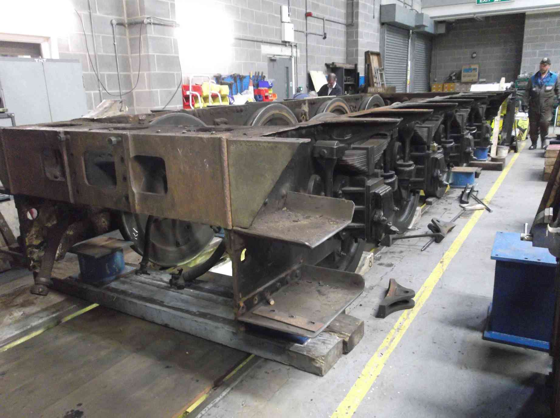
With the tank secured, we then moved onto lifting the tender frames to release the axleboxes, and also to allow the tender wheels to be rotated sufficiently to allow access to all areas of the inside of the frames and outer surfaces of the wheels. We used the same lifting technique as used on the tank, but access to the bottom of the frames for jacking and packing is not as good as the flat bottom of the tank. Eventually the frames were lifted sufficiently and left on the packing until they can be lowered back on to the axleboxes.
The lift went very well and thanks must be given to the Lift Team Leader and the team members, most of whom were there throughout the three days.
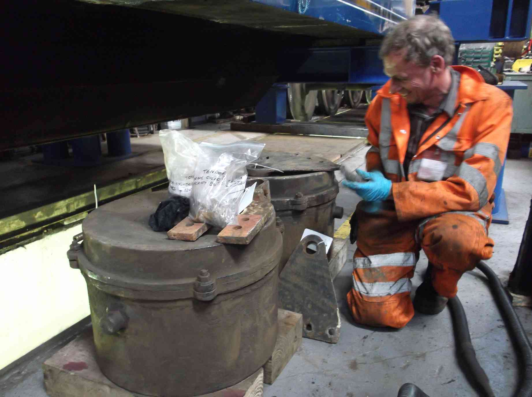
With the tender tank lifted, the vacuum cylinders and their brackets were removed. These will now be evaluated and overhauled. The work on the tender frames has also progressed with the removal and dismantling of the axleboxes.
This is the 29th update. You can read all the previous instalments here.