Locomotive Engineer Darrin Crone provides us with an insight into recent weeks’ work on the restoration of the great locomotive.
Week commencing 28 August
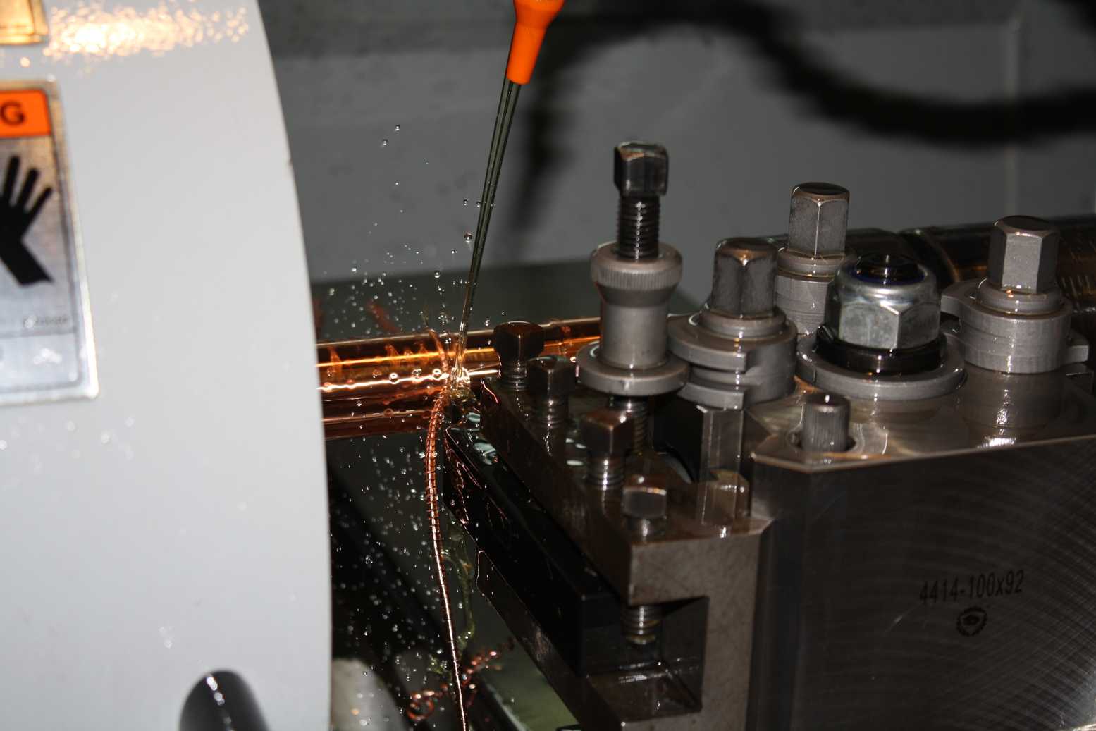
During our summer shut-down over week 34, we had a meeting at Llangollen to inspect progress with the boiler. At the same time the boiler doors previously prepared at York were handed over to the engineers at Llangollen. The sling stays have all been removed and we have supplied a drawing so that new sling stay pins can be made. The side sheet on the right-hand side is fitted and some trail staying has been carried out. All the remaining copper stays are to be machined on their CNC lathe soon. The material has been purchased and we have test certificates confirming its chemical composition.
The final documentation package was received from the wheelset repairers last week, and was inspected in detail and approved by SNG Engineers this week. The haulier who took the wheelsets from York has been contacted and plans are now being made to transport them to York as soon as possible.
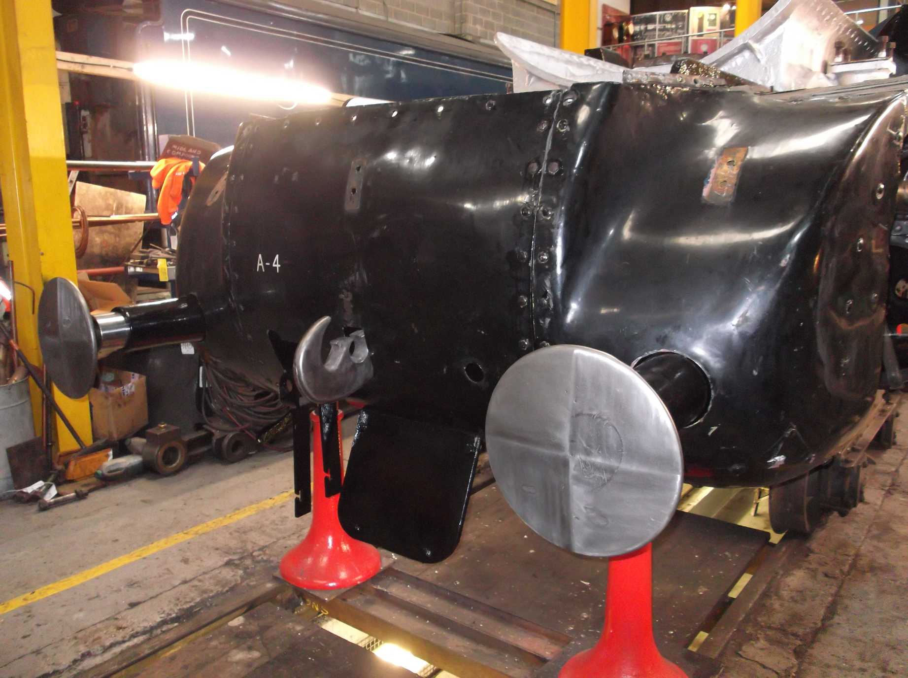
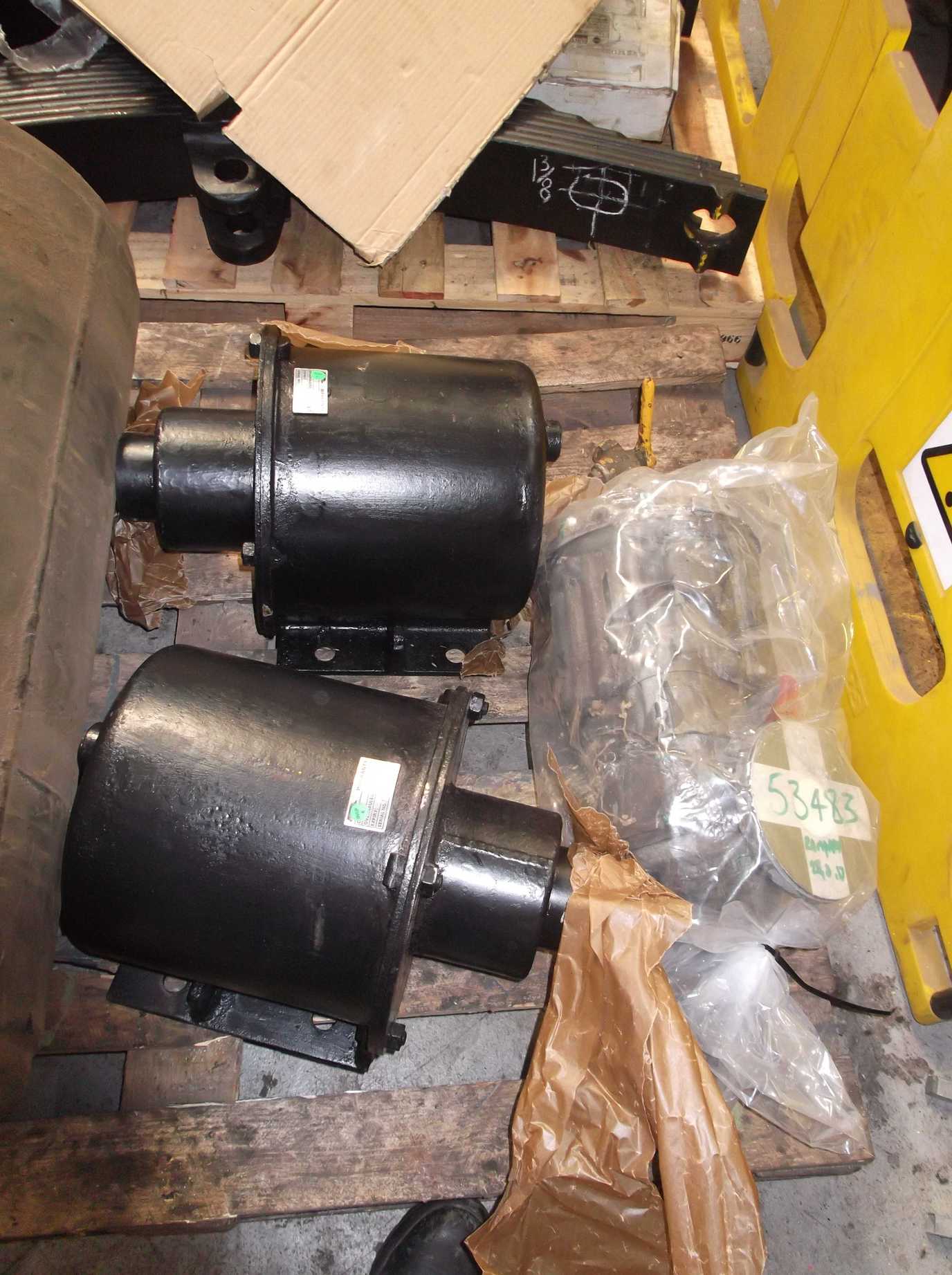
The leading sandbox fitting was completed this week, with the last split pins put through the mounting studs. The operating mechanism and new gaskets have been fitted to the right hand side.
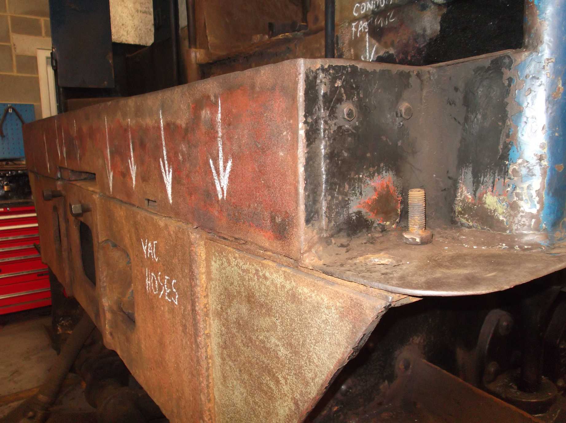
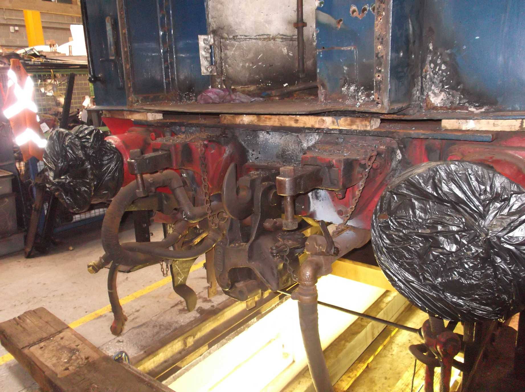
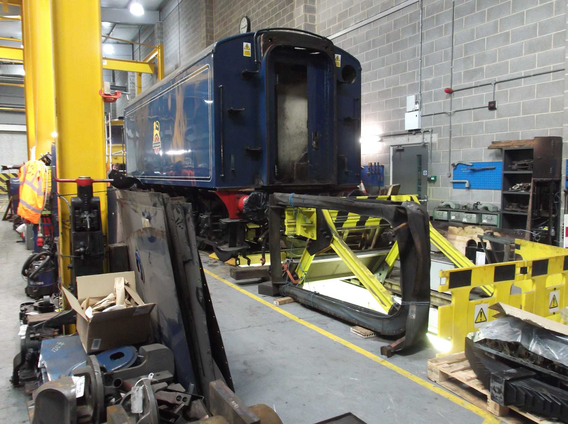
The front of the tender and coal space has seen further descaling. More bolts have been removed that are holding the tank on to the frames, with the help of the burning gear and a big hammer. Also some welds have had to be cut through to release the tank. At the rear of the tender the electrical cabinet fitted in the corridor connection has had to be removed as it was on top of some of the bolts securing the tank to the frames. The cabinet had to be dismantled to get it out. It was also necessary to remove the corridor vestibule door.
After the electrical cabinet was removed, the counter-sunk bolts underneath had to have their heads drilled out. We are now planning the preliminary lift of the tender tank. Packing is being sourced from a local timber merchant who has railway sleepers at competitive prices and who can also cut them to suitable lengths. The Engineering Team Leaders are formulating a plan and carrying out the risk assessment. This lift is only to prove that the tank can be separated from the frames. We plan to leave the tank sat on packing on the frames for now.
As part of the separation of the tender tank from the frames, the air brake pipes that go from below footplate to the receivers on the top of the tank had to be separated and those lower down removed. The removed pipes were identified, cleaned and have been annealed.
The remaining rivet holes on the frames were given a last inspection this week and we revisited a couple with the reamer just to give them one last clean up. The countersinks were also given a further skim as the last left-hand one, removed a few weeks ago, had yet to be done for the first time. The opportunity was taken to use the set-up on the others. Seven out of the nine rivets needed were machined and fitted on Saturday, being jacked in. It was quite an ordeal as the jack pump was out of oil and it took some time to bleed the air out of it. Normally a straightforward job, it was left until last, and so it was a late finish.
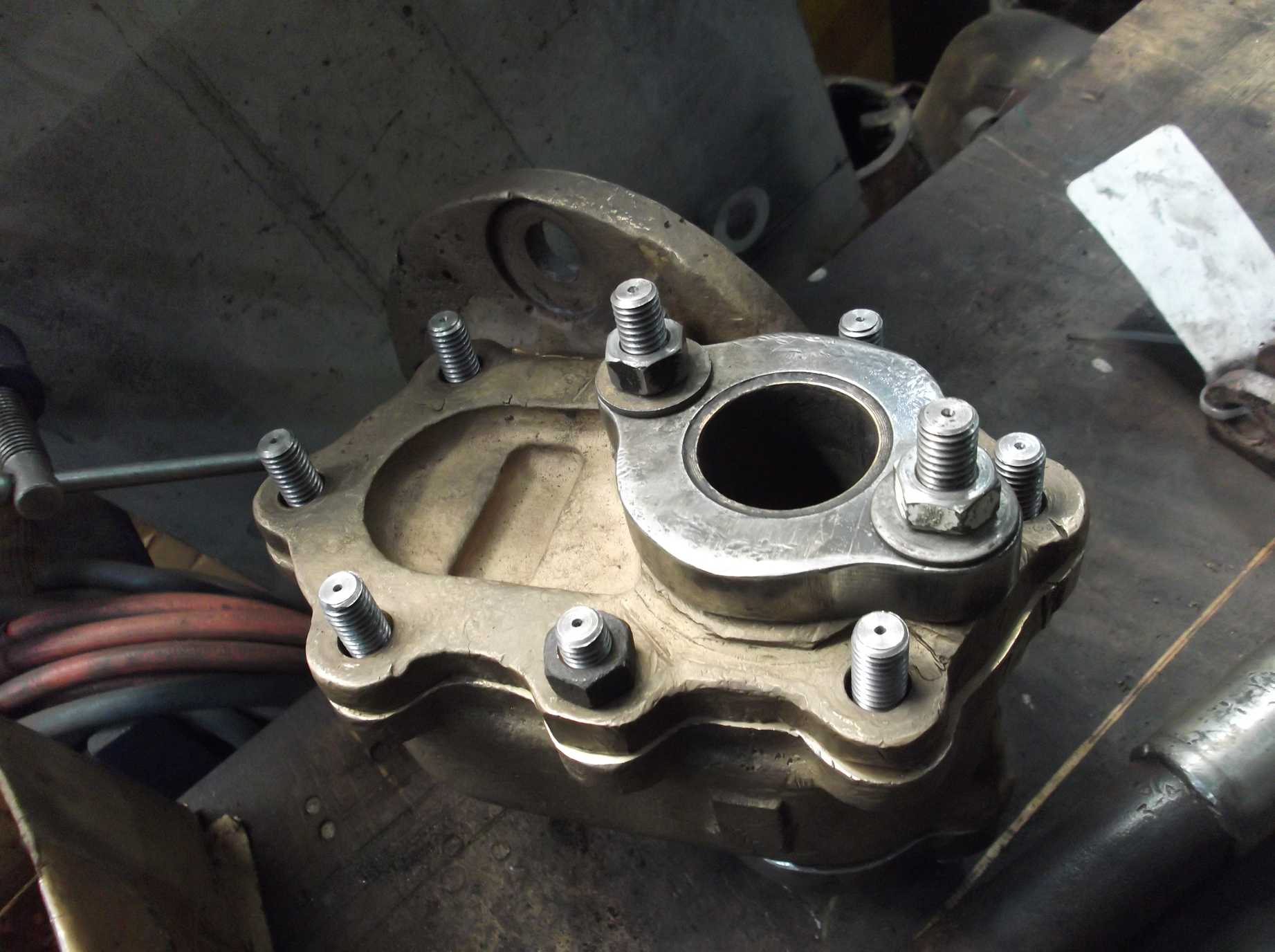
The regulator stuffing box cover fitting was completed this week. After the fitting of new studs the cover wouldn’t go on. The cover holes were cleaned of some remaining carbon deposits and a few studs were swapped round and now the cover fits fine.
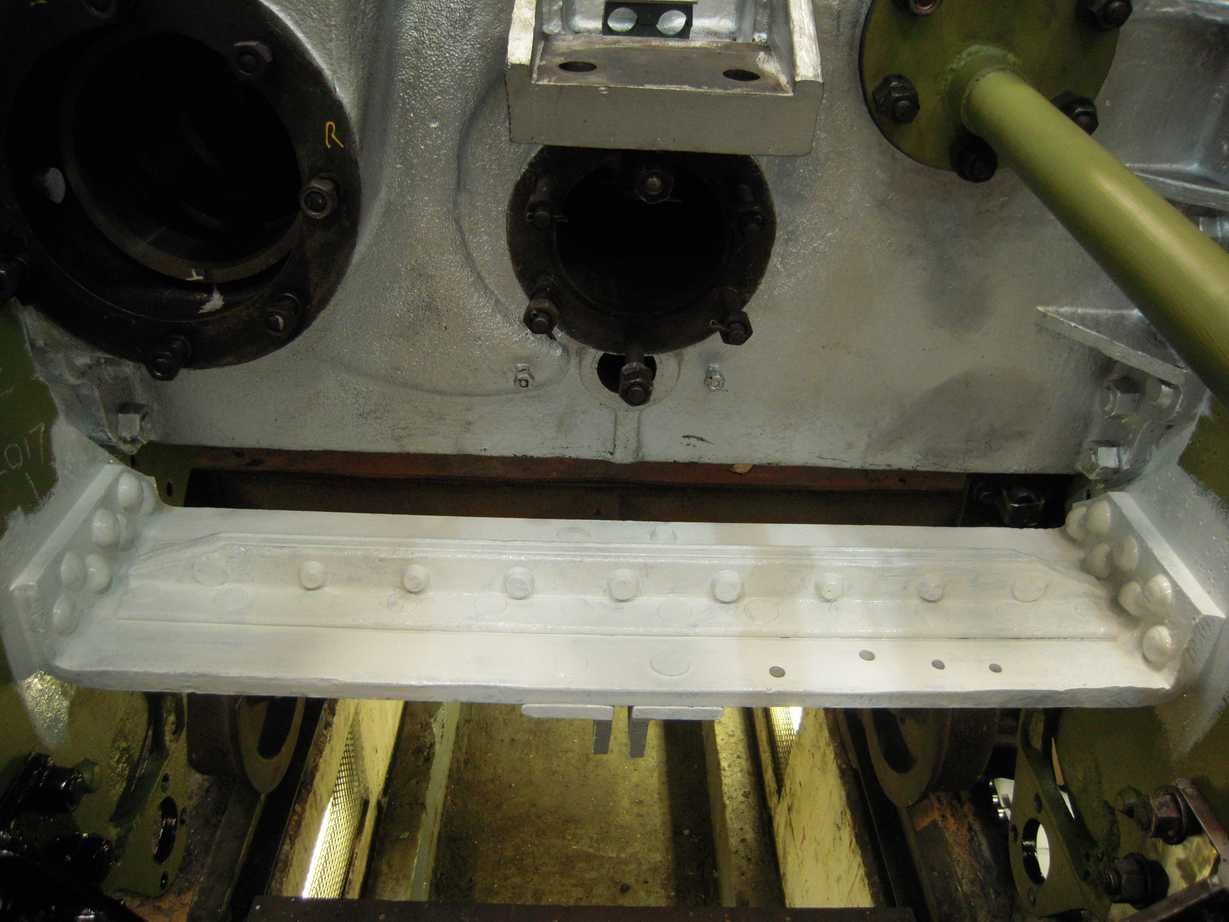
The leading brake cylinder stretcher was painted this week. The last replacement rivets were put in a couple of weeks ago and these have been tested so the stretcher could be painted. The re-bushed brake cylinder trunnions are now finished and can return to York, when transport can be organised.
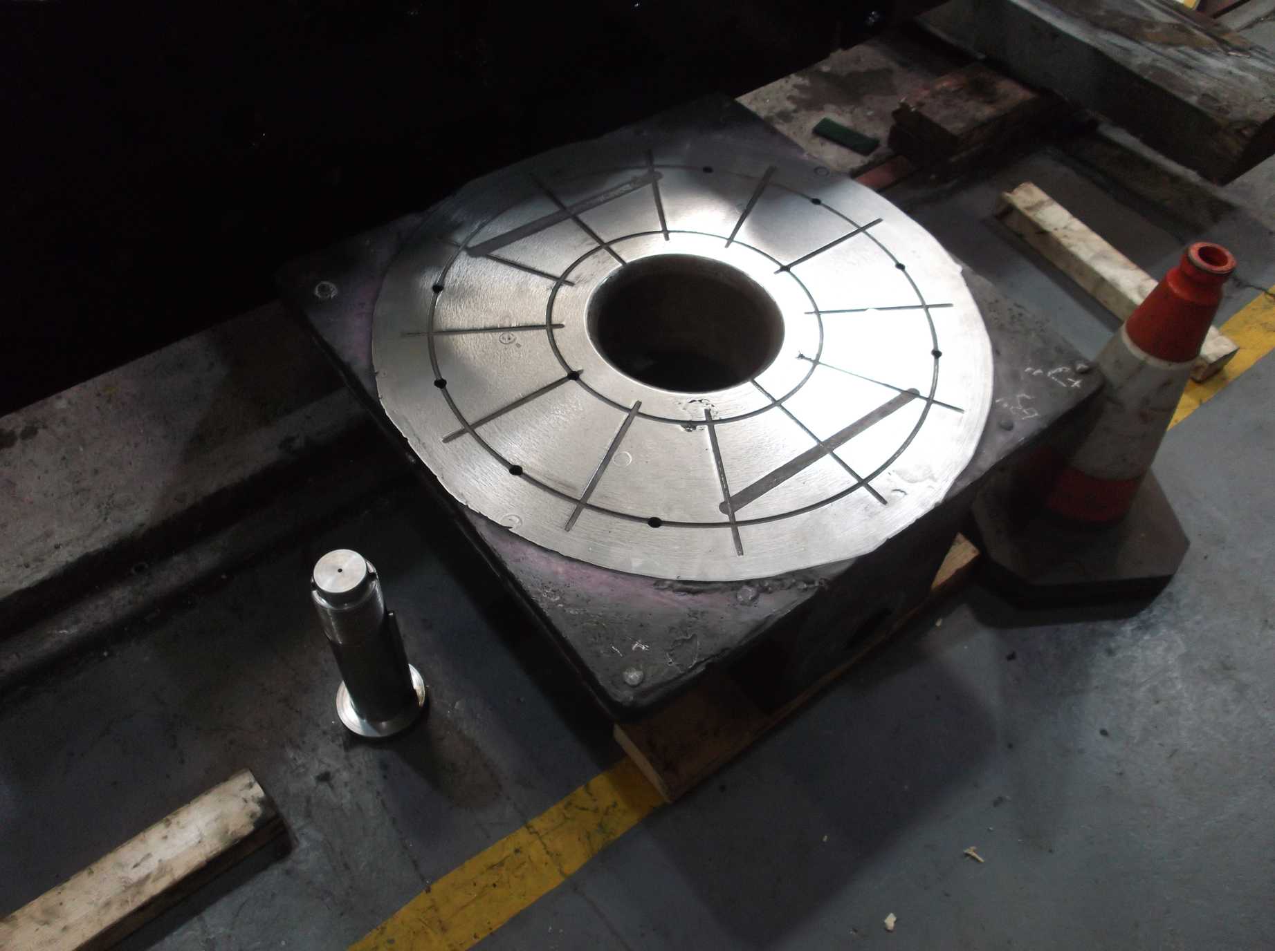
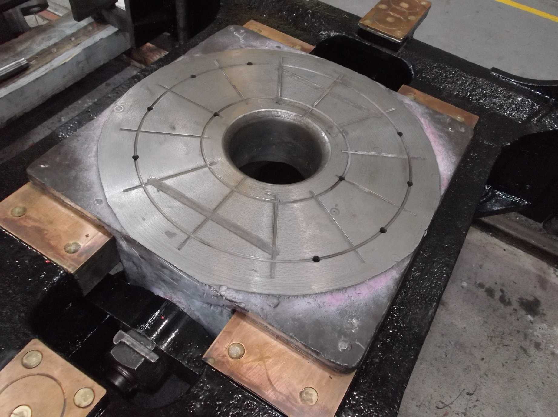
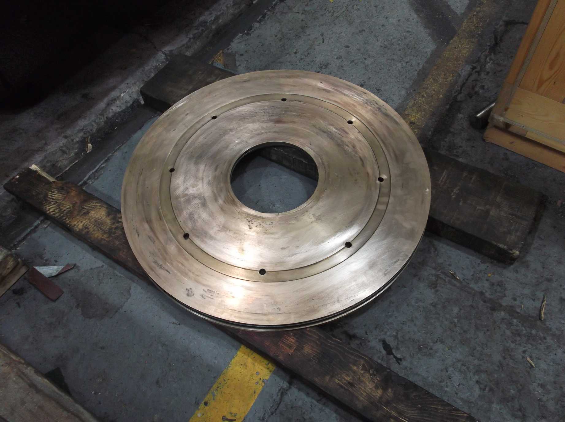
The bogie centre casting was tried on the bogie frames this week. Some feeler strip was used to go round to check the fit. The bearing surfaces on the centre were also checked with a precision straight edge. The centre was also inspected on the workshop surface table and measurements taken of the variation in height of the lower bearing surfaces. The dimensions were discussed with our CME and the centre has now been accepted and will be ready for fitting when the top surface is polished, as we have done to the lower surfaces.
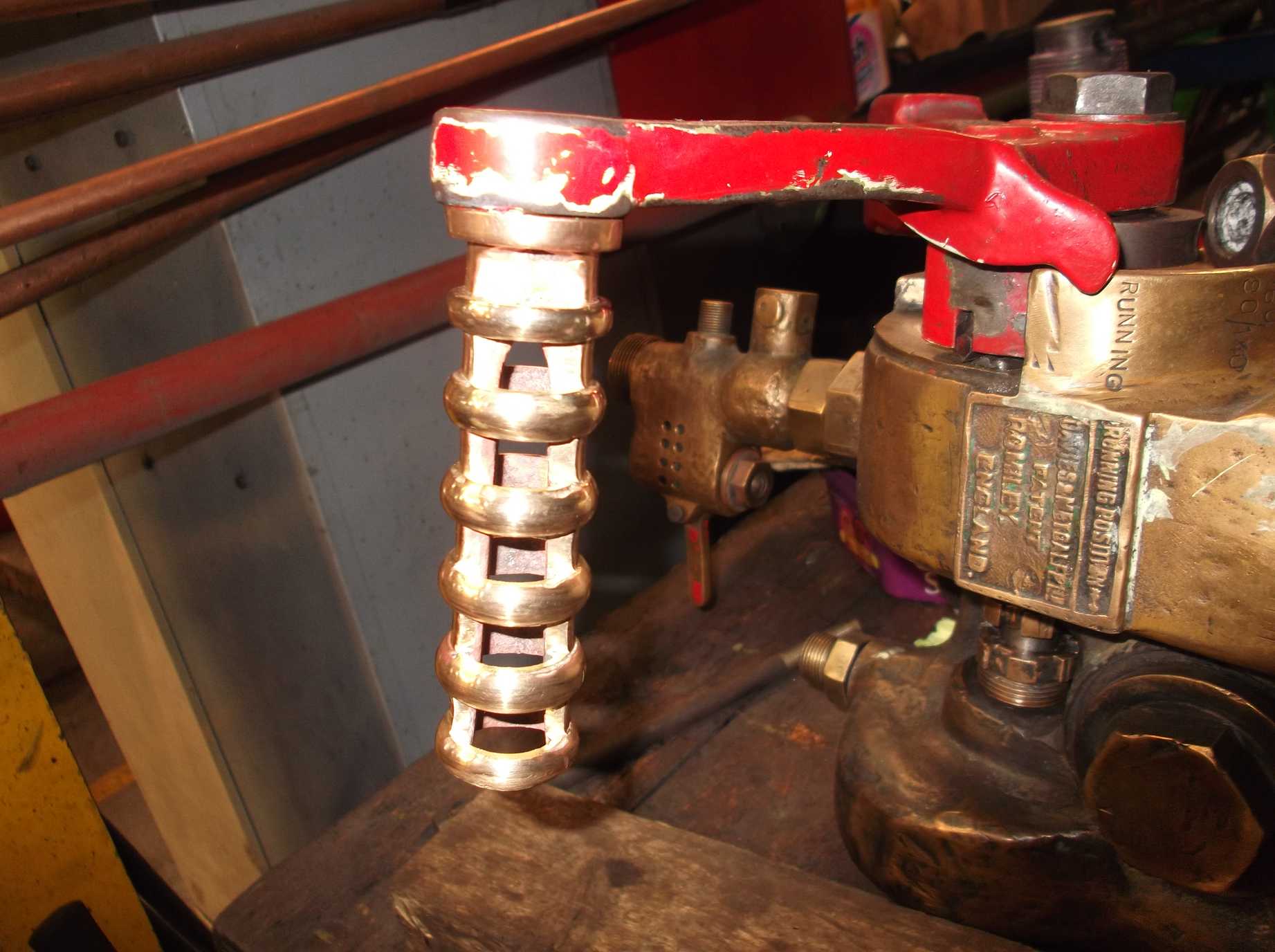
The ejector brake application handle was worn by years of use. It is a brass or bronze casting made of a row of spaced rings so that it stays cool. Some of the rings had worn thin and had started to collapse. The handle was taken for repair as homework by one of the volunteer Engineering Team, who has done a marvelous job in retaining the original handle and reinforcing the rings with new material. It feels really good in the hand. The same volunteer has also supplied us with a new set of piston valve packings, free of charge, which will be stored in a safe place until needed.
The recently fitted liners have been inspected by our Chief Mechanical Engineer. He has taken measurements and they are within tolerance so require no further work. Dimensions for the machining of the valve heads can now be calculated.
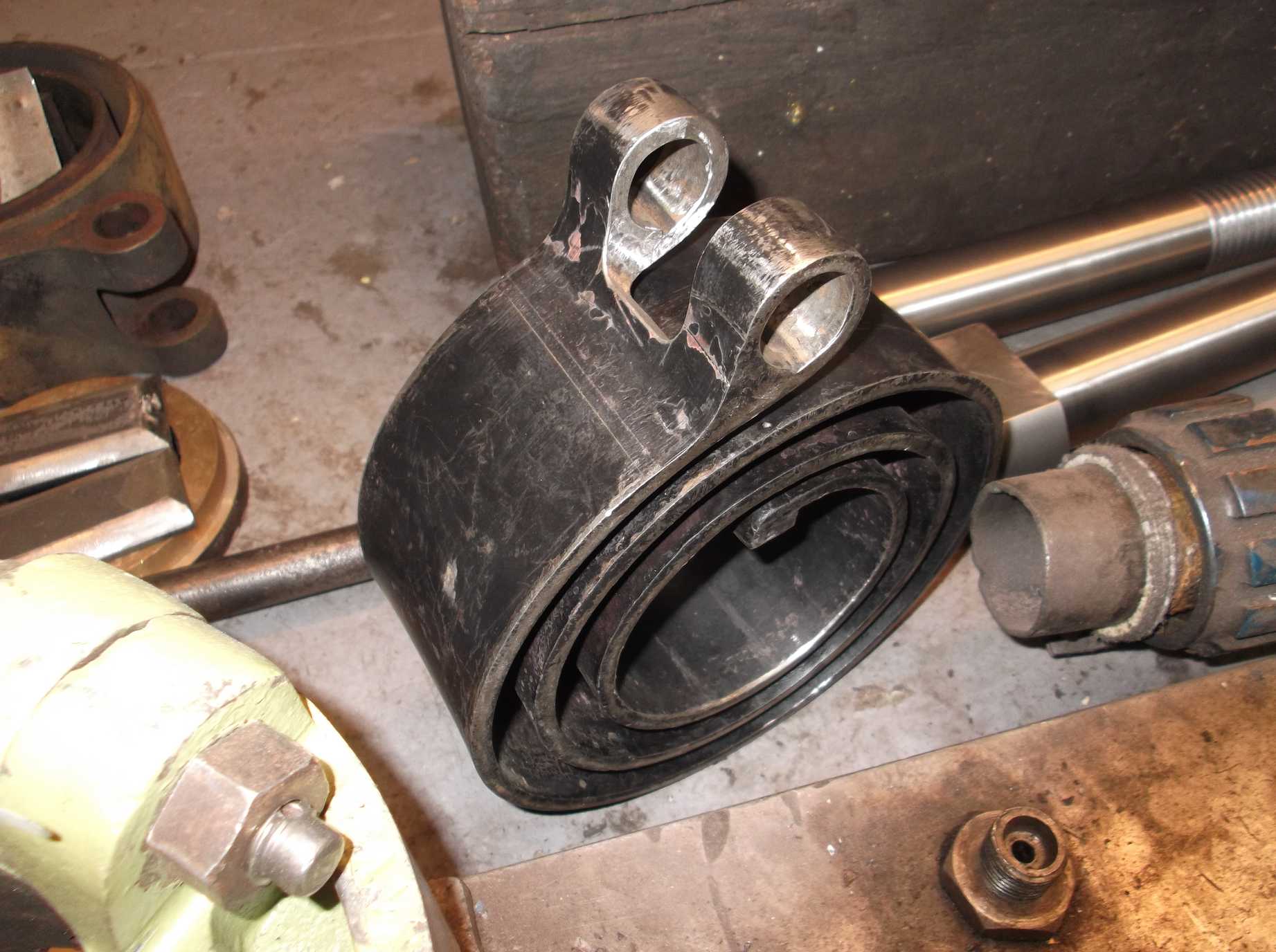
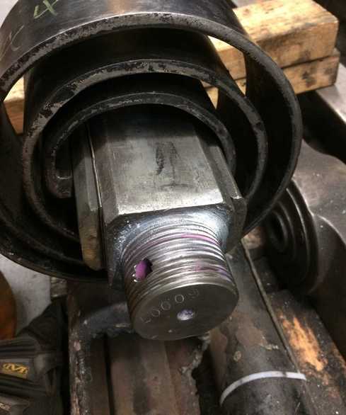
The new spiral spring for the reversing shaft was finish fitted to the mounting bolt and pin. It is a very good job which has taken some time to get the cut-out shape needed to fit the bolt with no stress raising corners. It was tried on the end of the shaft and it is vert tight. It seems that it is not going to be an easy job to get it on the shaft when the shaft is threaded through the frames.
Week commencing 4 September
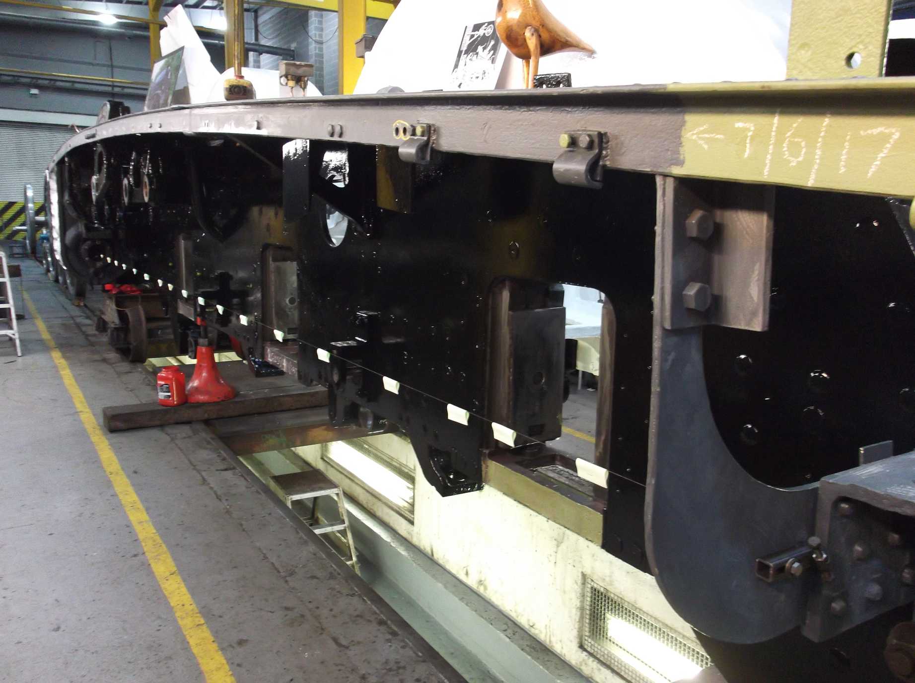
The bulk of the fitted rivets for the spring hanger brackets were put in this week. We still need to fit two to the leading right-hand bracket and this week we obtained the material from which these larger rivets will be made. All other rivets but one are now in and hammered over, as we ran out of oxygen for the burning gear. Fresh supplies were collected on Friday.
The packing for the tender tank lift was sourced and brought in on Tuesday. While everybody was on riveting, one of the engineering team volunteers sorted the packing towers for jacking. After our last rivet, the engineering team then moved to trial jacking the tender tank. The front corners of the tank were carefully lifted a few inches, proving this is now free. One final bolt was found which was cut off with a grinder, but after that the front lifted without problems. We also continued ensuring the tank was free to lift at the back. The hydrant water filler pipes that go through the frames were removed and more material was taken from the awkward countersunk bolts along the top of the rear bufferbeam, across the vestibule floor.
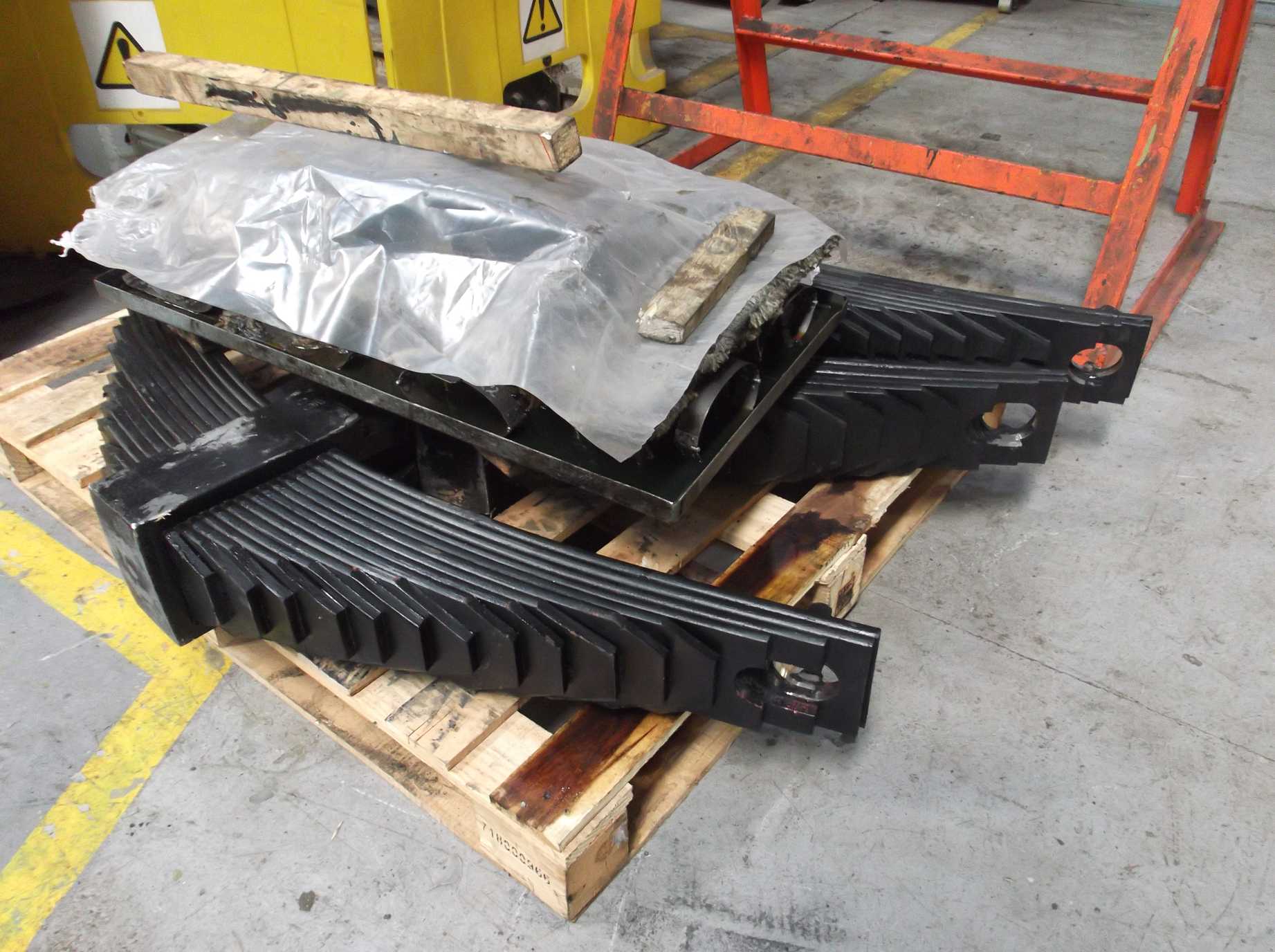
The loco coupled springs were examined this week for the fit of the spring hanger bolts. The old bolts had considerable wear from contacting the springs in traffic. To ensure the best clearance for our new bolts any overlapping leaves are being ground back to ensure a clear hole for the bolt to go through. The dimensions of the hole is detailed on the BR drawing of the spring and this will be closely adhered to. This work is following advice from the company who refurbished the springs.
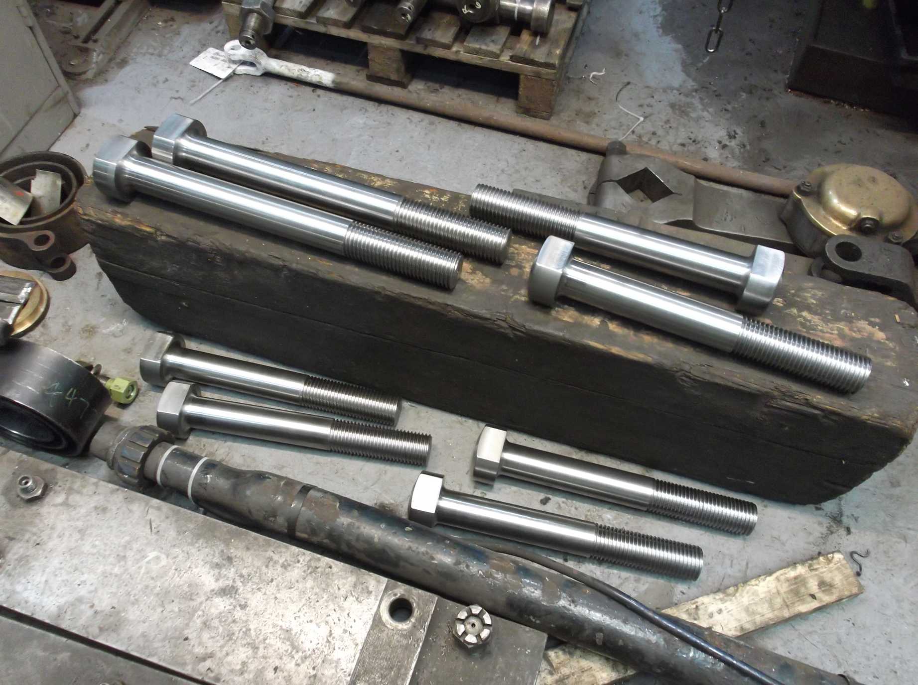
The delivery of the new coupled wheel hanger bolts was completed this week.
The fit of the bogie centre casting was checked last week and this week it was fitted. The top circular bearing surface was polished and the new bogie side control bolt was fitted by filing and scraping the bolt key. After making sure that the new bolt was a good fit, the centre casting was lifted in to the bogie frames. The rest of the side control components were assembled and secured with the nuts on the side control bolts. The cotters that go through the bolts require final fitting. The side movement is limited by the end of the bolt and a stop in the side of the bogie frame. This was measured and matches the nominal 4″ specified on the LNER drawing.
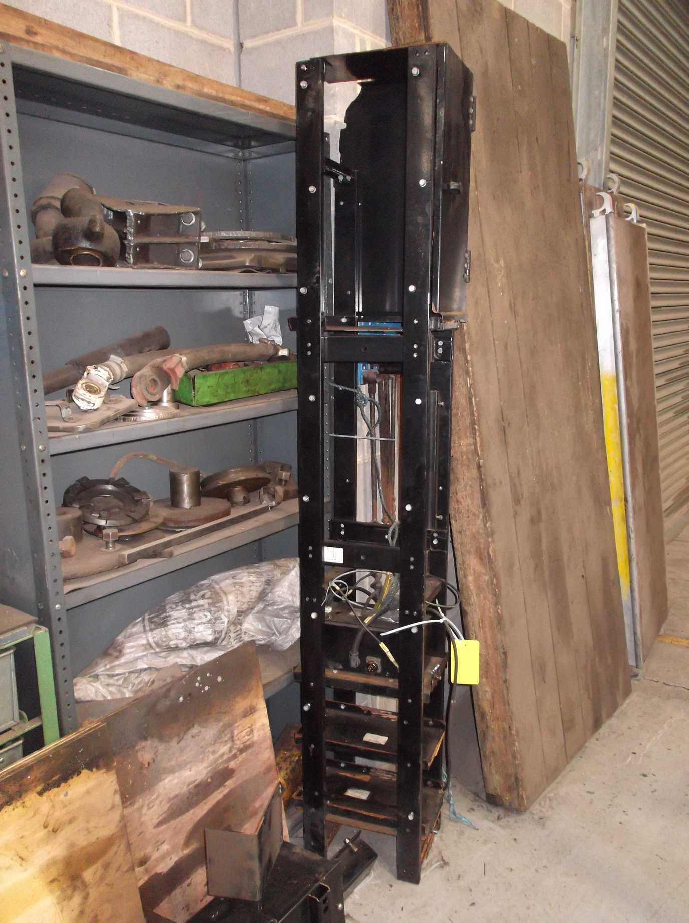
The GSMR frame was removed from the tender last week and this week some of the components were reassembled so that they don’t get misplaced, and we know how the thing goes back together. Detailed notes have been made recording the assembly.
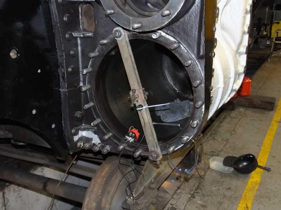
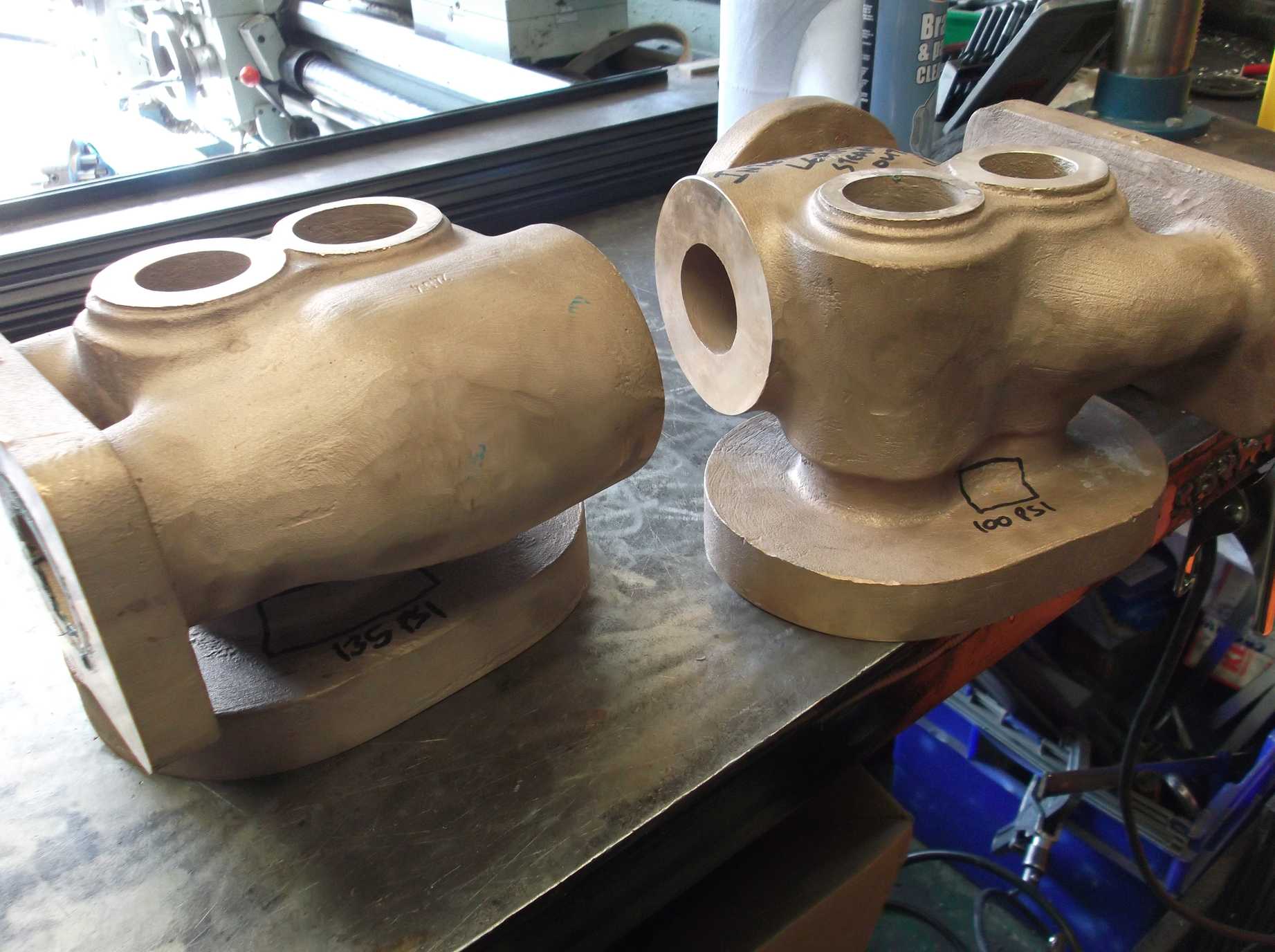
The clackboxes are being machined by contractors and are ready for initial pressure test. First signs are that they have cleaned up well, butone does show some minor porosity, which is not unusual in this type of casting. The internal components for the clackboxes were delivered to York this week. They are a mixture of refurbished and new parts. When the clackboxes have had their initial pressure test they will be finish machined, assembled, then pressure tested again to ensure there are no internal leaks.
The coupled wheel and bogie axleboxes have had the whitemetal melted out of their crowns and await the casting in of the new material. The wheelset’s return to York has been organised for early next week, and the first job will be the removal of the grease protection to the bearing surfaces. When this is done they can be measured and the finished sizes of the bearings calculated.
On Saturday the 007 Gang of junior volunteers were working with us again. They all had a spell of rubbing down the frames. The junior volunteers also fitted two new bolts to the regulator valve operating lever assembly and then helped to drill the bolts through for split pinning. The bogie bearing plates that fit between the loco and bogie were also retrieved and cleaned for inspection. The junior volunteers also helped our Chief Mechanical Engineer to measure the ports in the new valve liners.
Week commencing 11 September
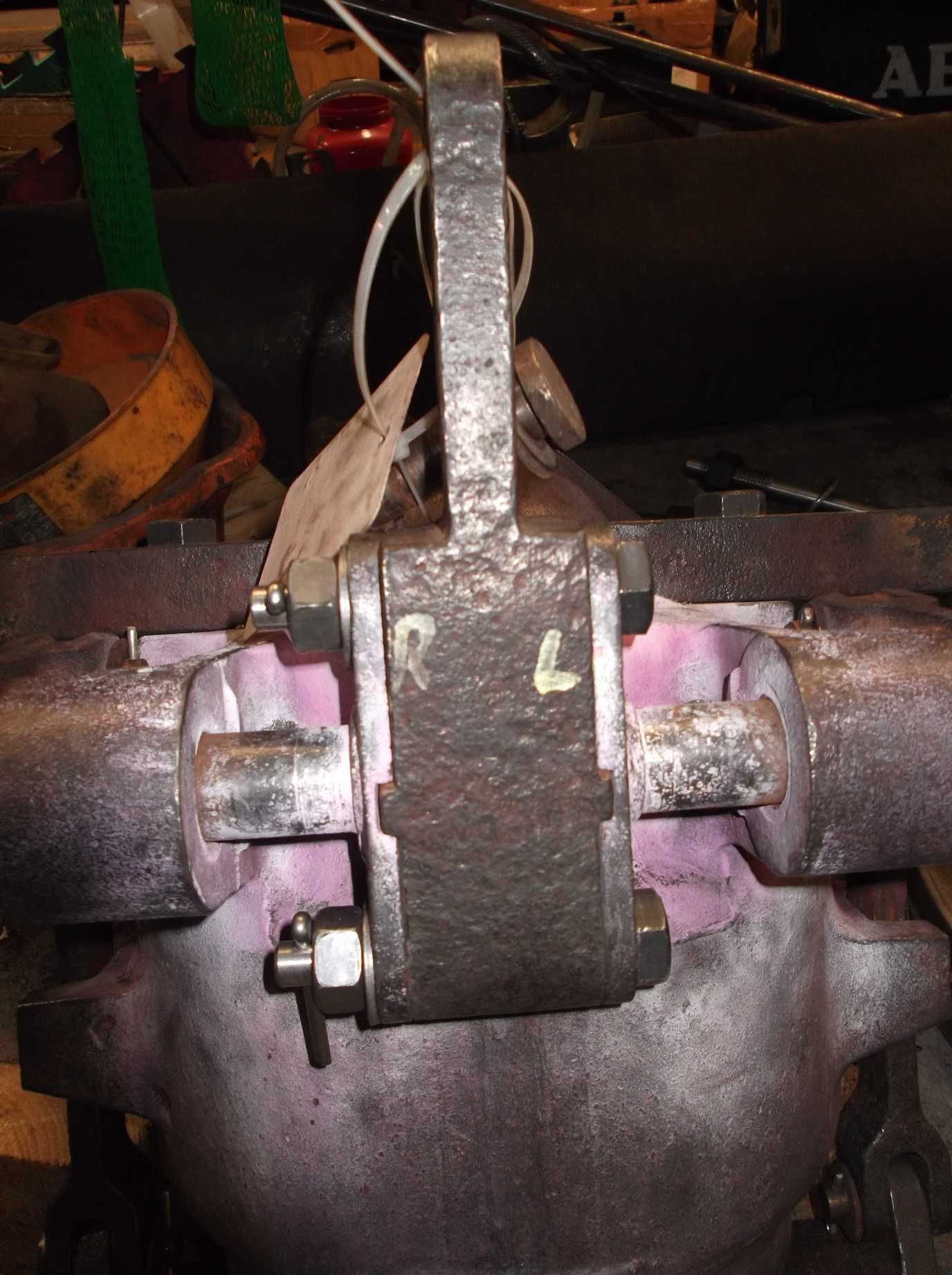
The leading loco vacuum brake cylinders were returned to York this week. The trunnions were measured and are spot on. This allows sizing of the bearings. The outside bearings were checked and the fit is good, but they are corroded so will be replaced. The centre bearing was set up on the loco and a wire put through from the outside bearings to check alignment. The centre bearing is smaller than the outside bearings and so gets more wear—it will need repair to replace material worn away as well as to return its alignment.
The repair of the streamlining threaded holes in the footplate angle around the front of the loco was completed this week and the tender hand brake handle and shaft was removed. This requires removal for the separation of the tender tank and frames.
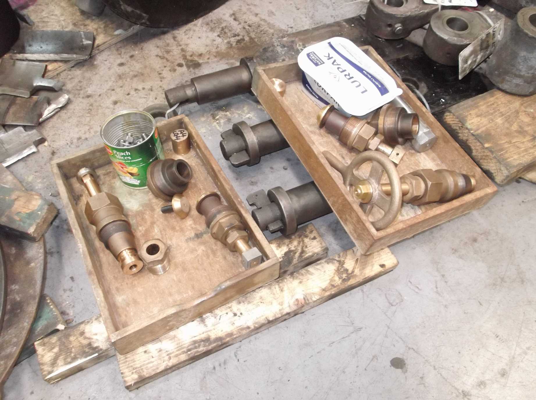
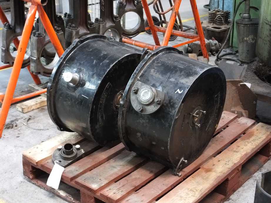
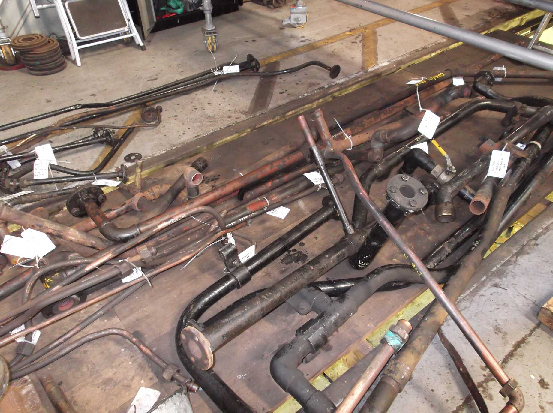
The tender water valves and connecting pipes were finally separated into component parts and cleaned this week. This has allowed them to be put in store pending their overhaul.
The last two fitted rivets for the leading right-hand spring hanger bracket were machined this week and then fitted. They will not be closed until the fitted bolts are in place but they do provide a tight, dowelled location for the bracket for further work.
The clackbox castings have now been pressure tested and disappointingly we have some failures. We need two, but have had a total of six castings produced to bring the unit cost down. The other four castings are destined for other locomotives. Final machining won’t commence until we have a full set of six sound castings—again this is to reduce cost.
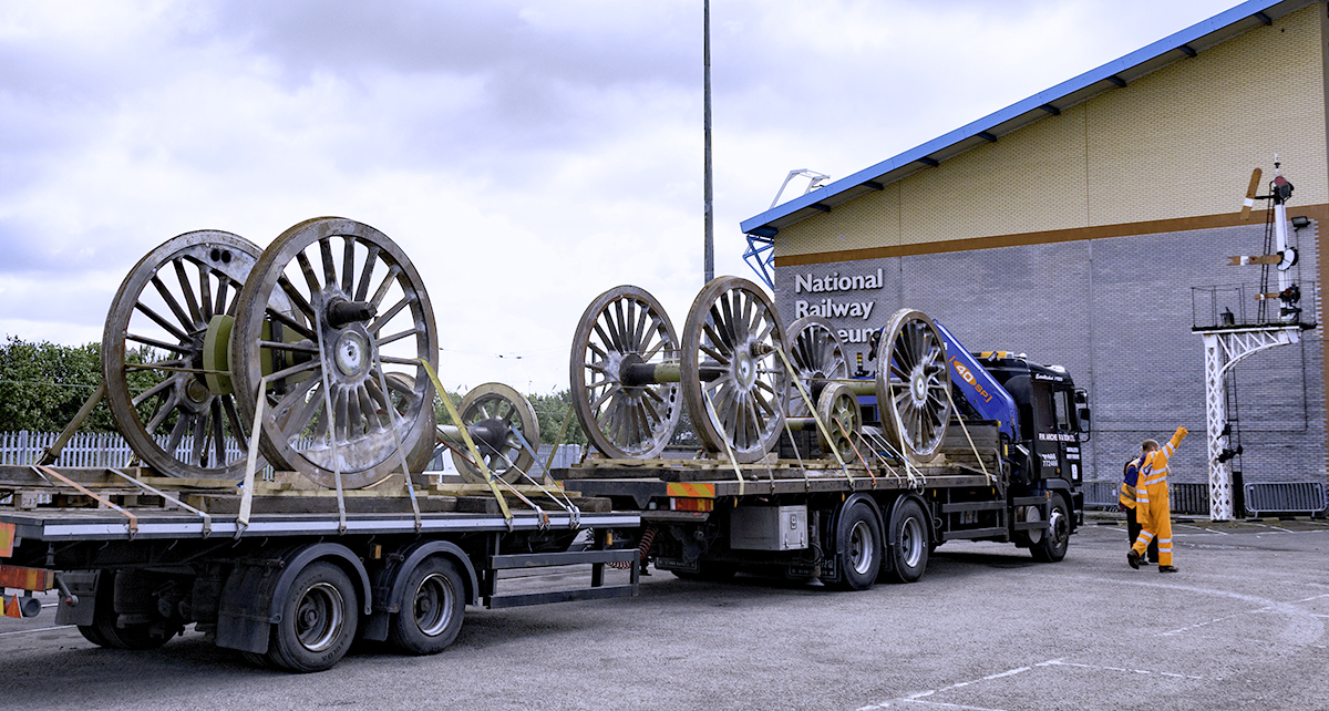
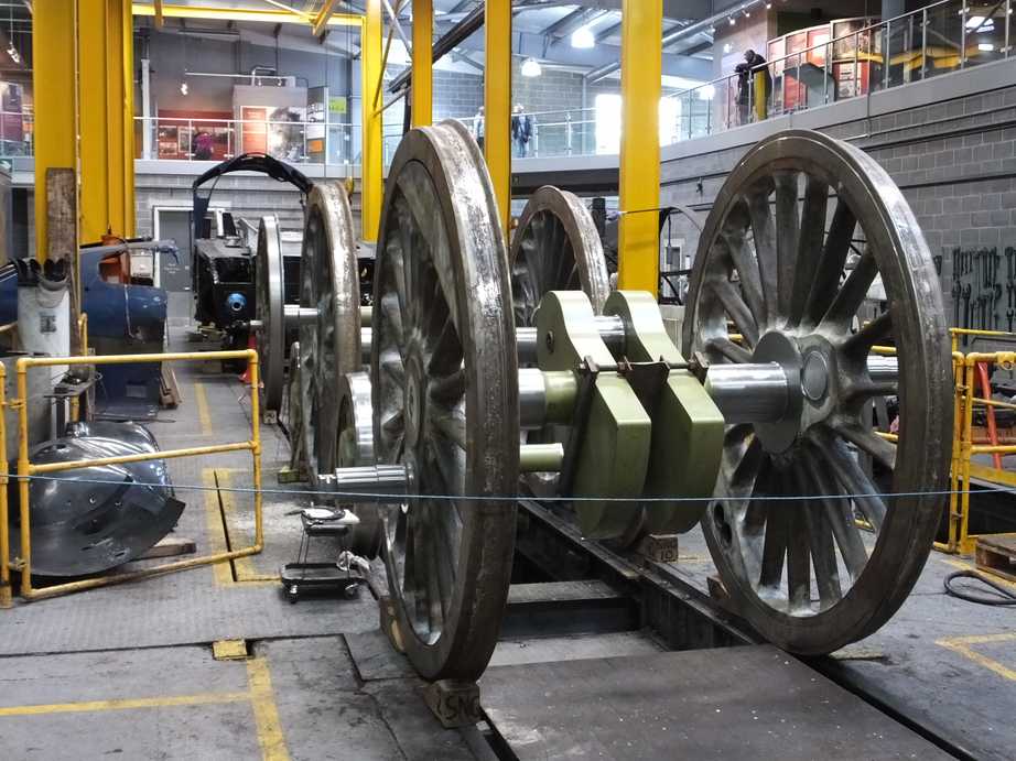
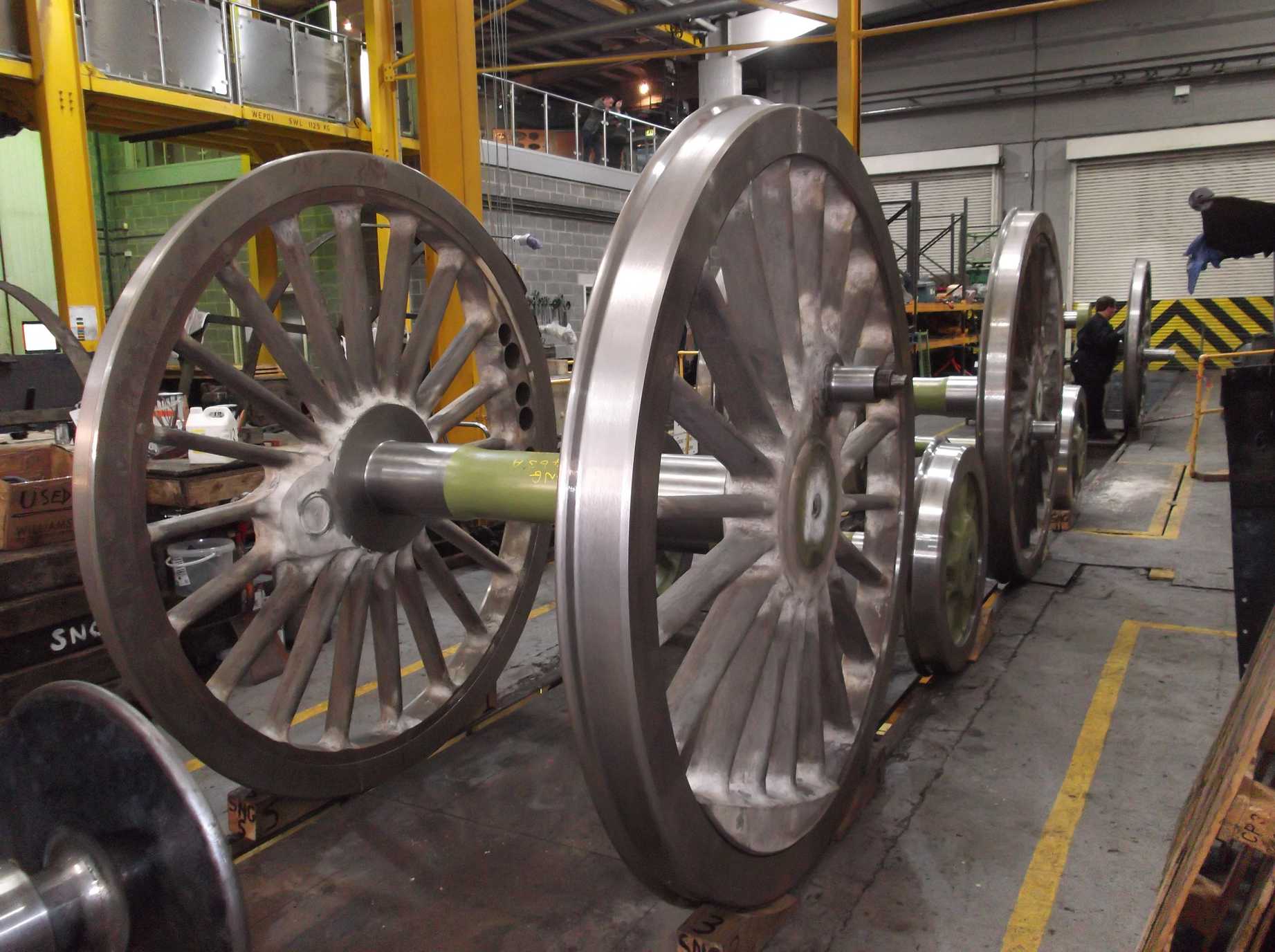
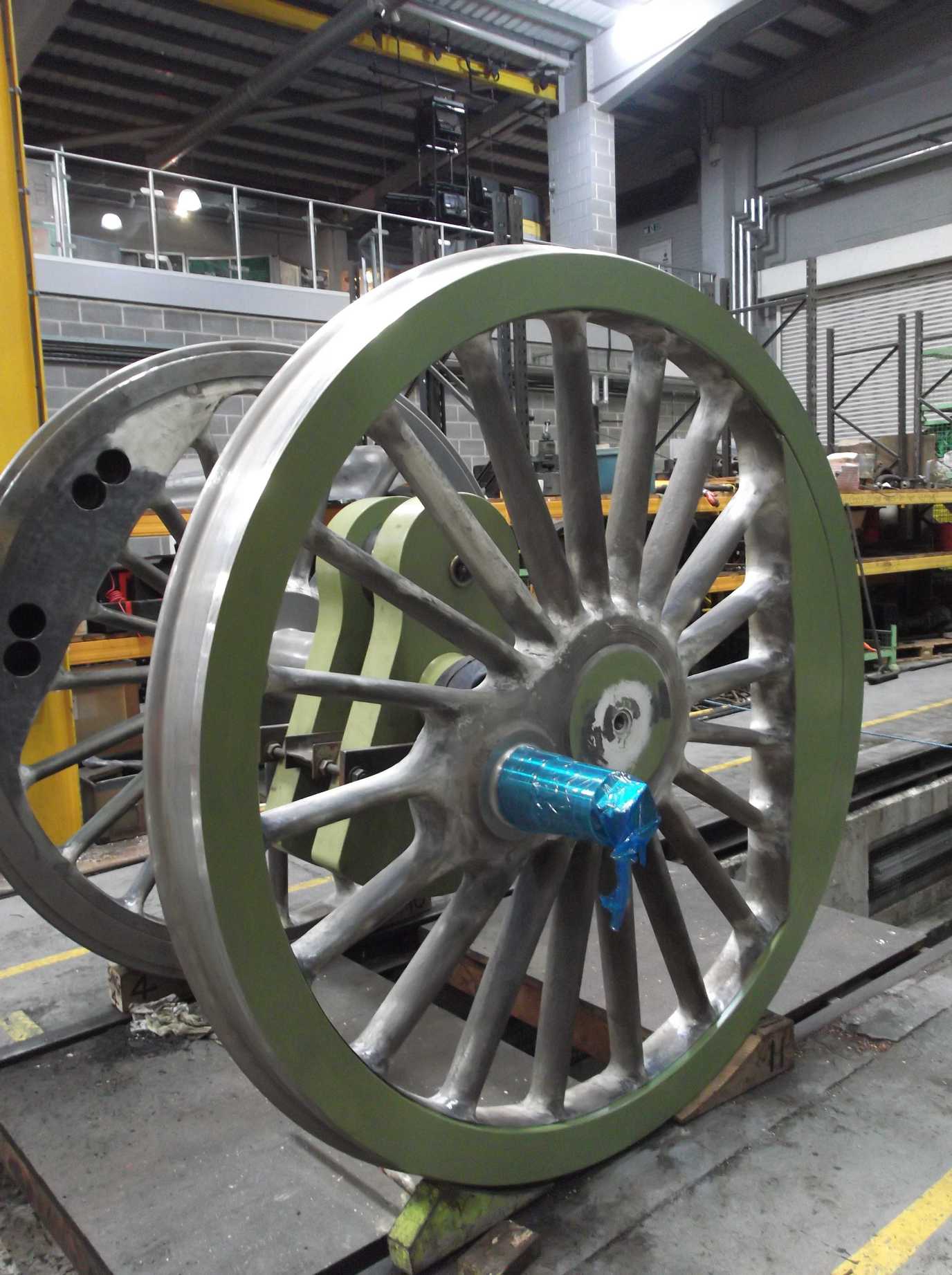
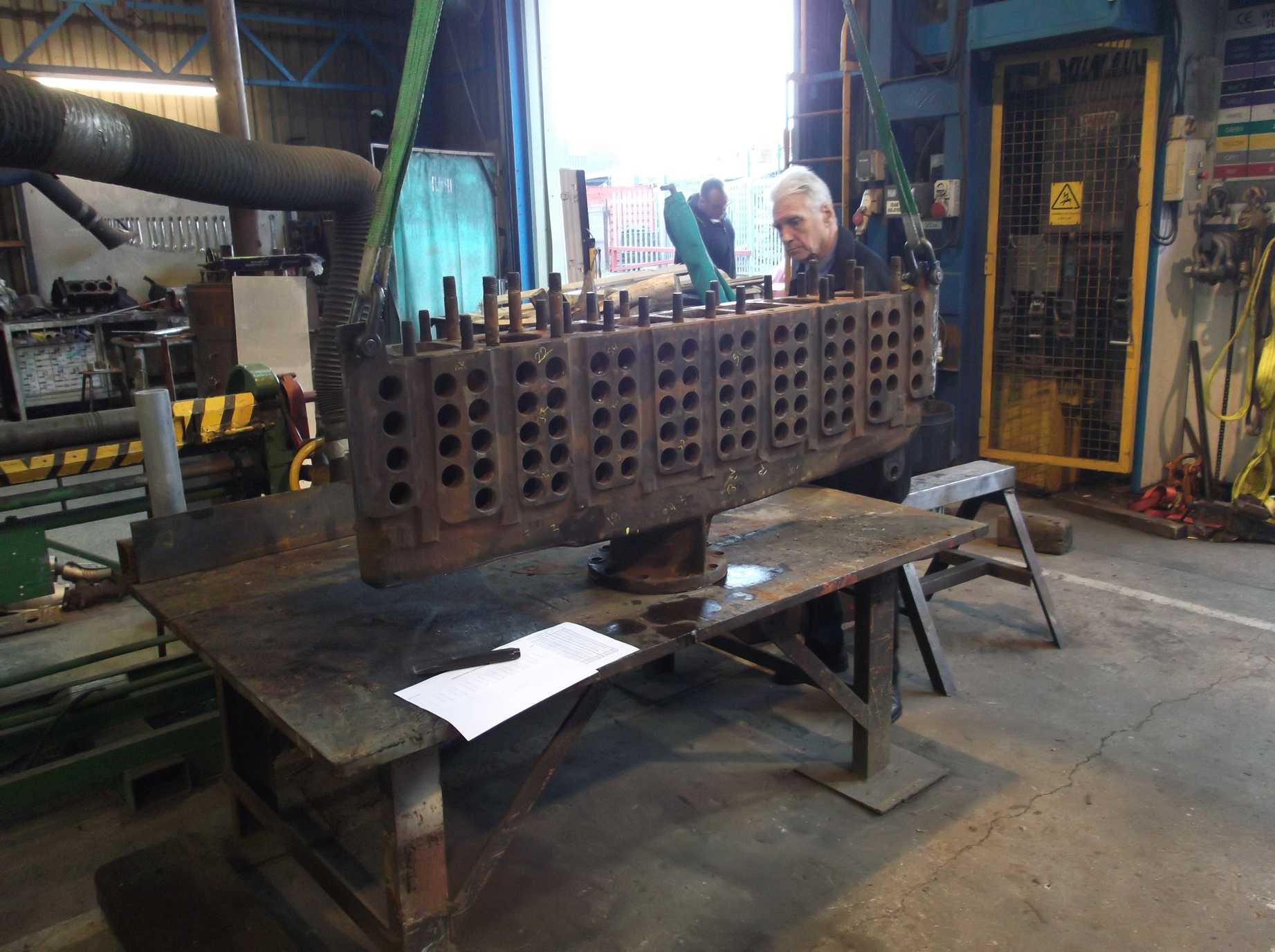
The big event this week was the return of the wheelsets from repair and re-tyring. They turned up promptly on Tuesday morning, delivered by Archer’s of Northallerton using the same procedure as when they left York, but in reverse. A rigid chassis truck brought the wheelsets into the confines of the workshop yard to get under the wheel-drop crane, then went back to the trailer left in the car park to retrieve the remaining wheelsets. The unloading went to plan, though the limit of lift was reached before the coupled wheelsets could fully clear Rocket’s boiler. To get the wheelsets past they had to be turned while over the boiler.
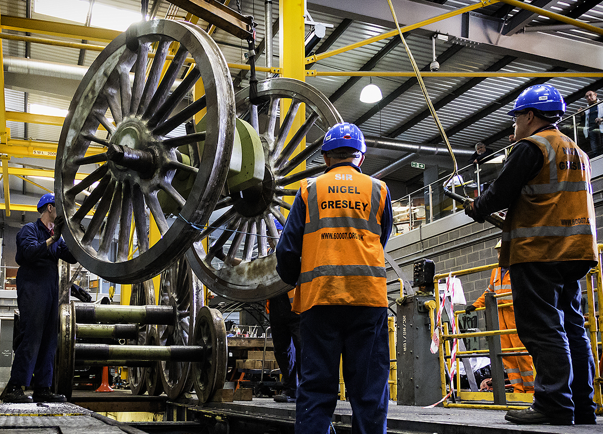
As soon as the wheelsets were down on the rail they were chocked, with chocks kindly loaned by haulier Paul Archer, then we began to remove the protective greased wrappings. Over the next couple of days the Engineering Team volunteers cleaned off the grease and wax. Good progress has been made but there is still much to do to get the wheel centres cleaned ready for painting.
On Saturday our Chief Mechanical Engineer Richard Swales made a start on measuring the wheelsets. The bogie sets are the first to be measured, as we know the axleboxes for these will have to be modified to match the dimensions that have changed due to the fitting of new lining plates.
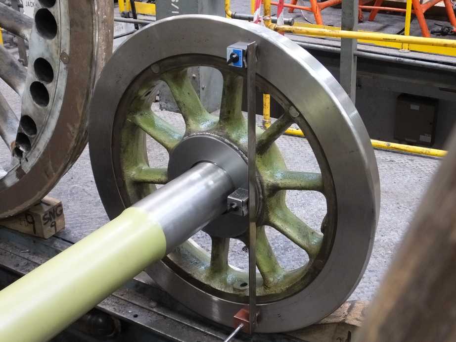
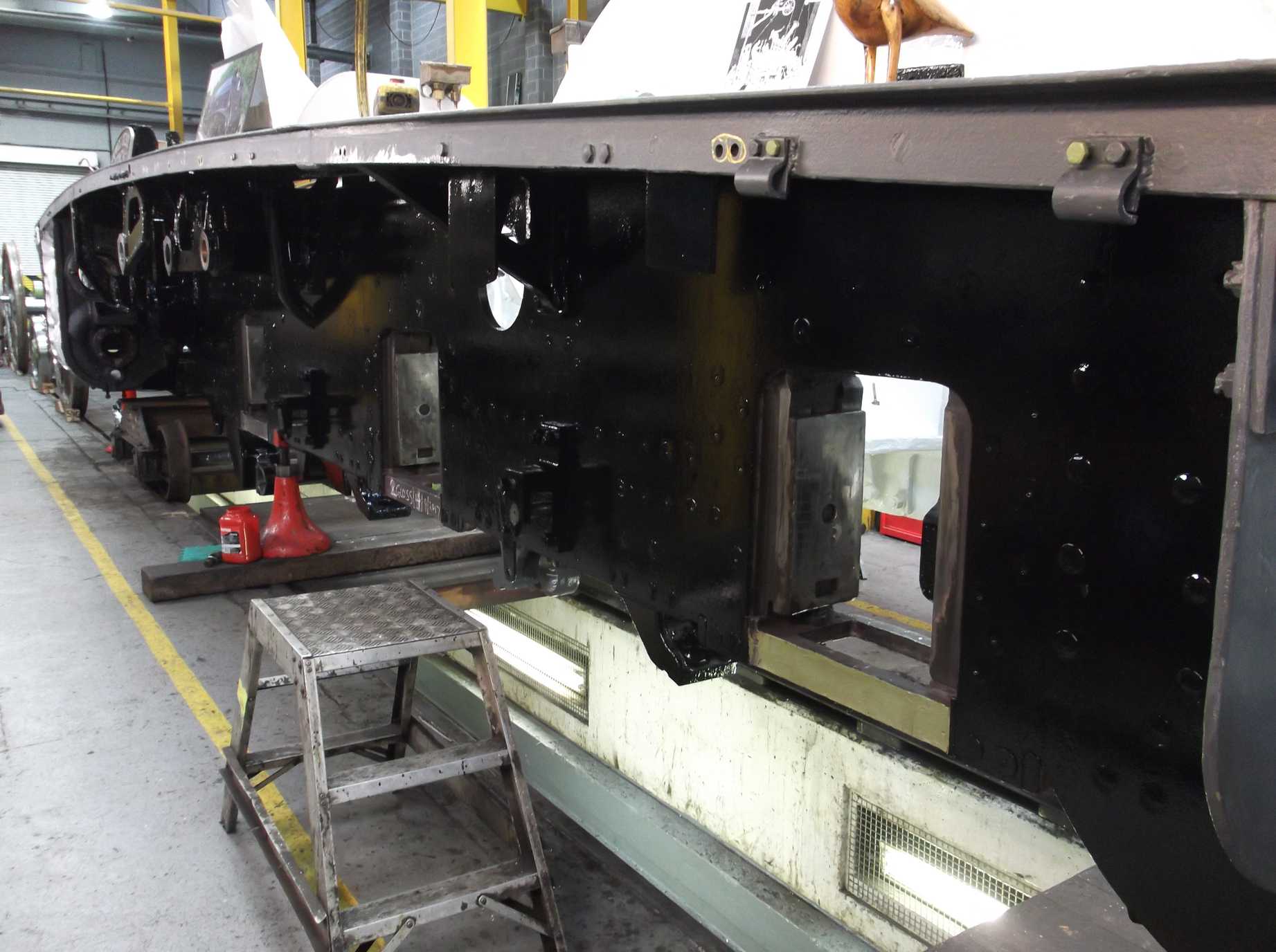
The left-hand mainframe plate has been painted to gloss top coat this week, allowing Richard to put up the left-hand engine alignment wire. The wire is set up on the cylinder centre line and in theory should pass through the centre line of the driving coupled axle, when in position, and be parallel to the slidebars. This can only be done when there is no work required in this area, as the wire has to be set up very accurately and must not be disturbed.
Week commencing 18 September
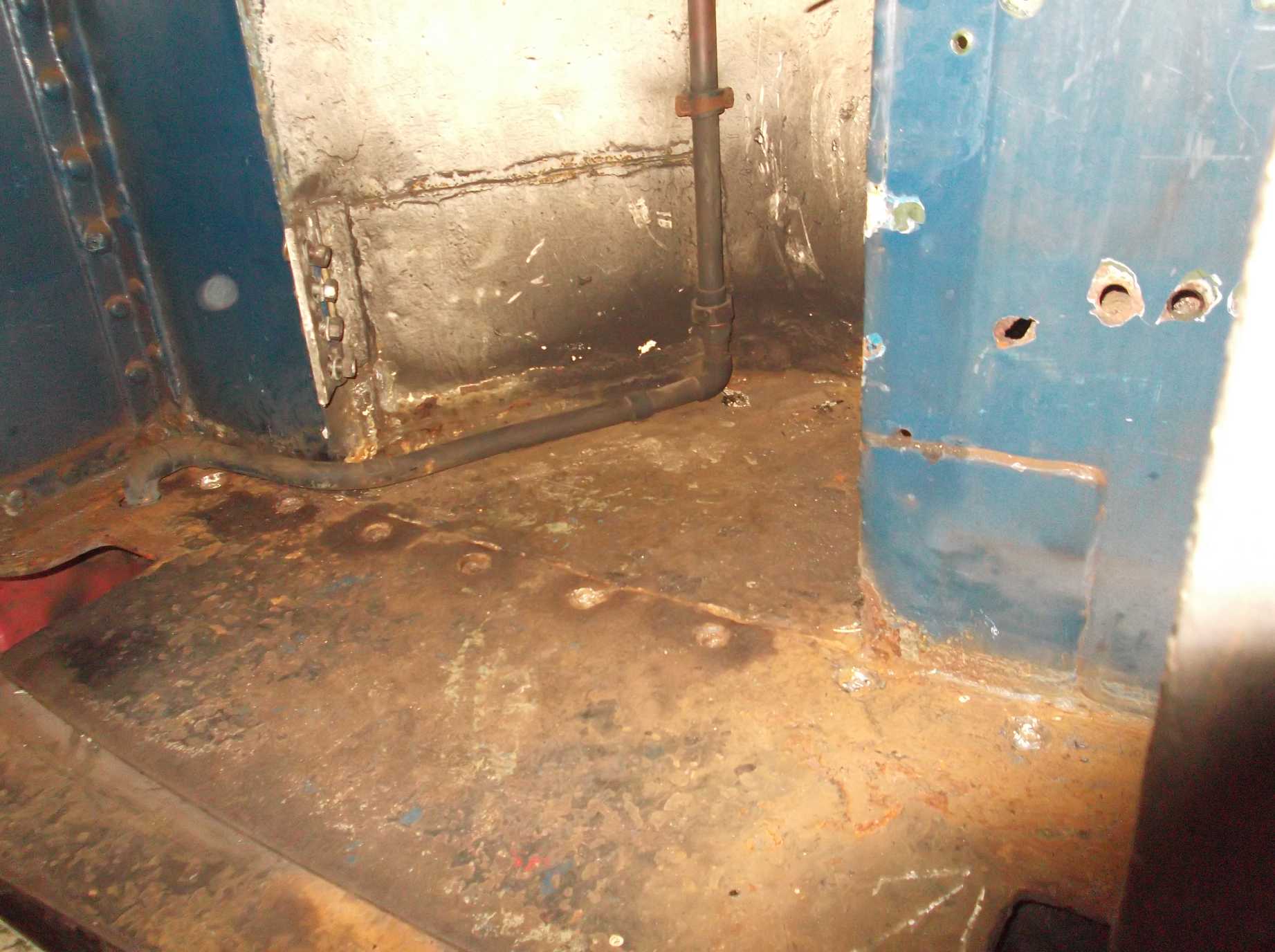
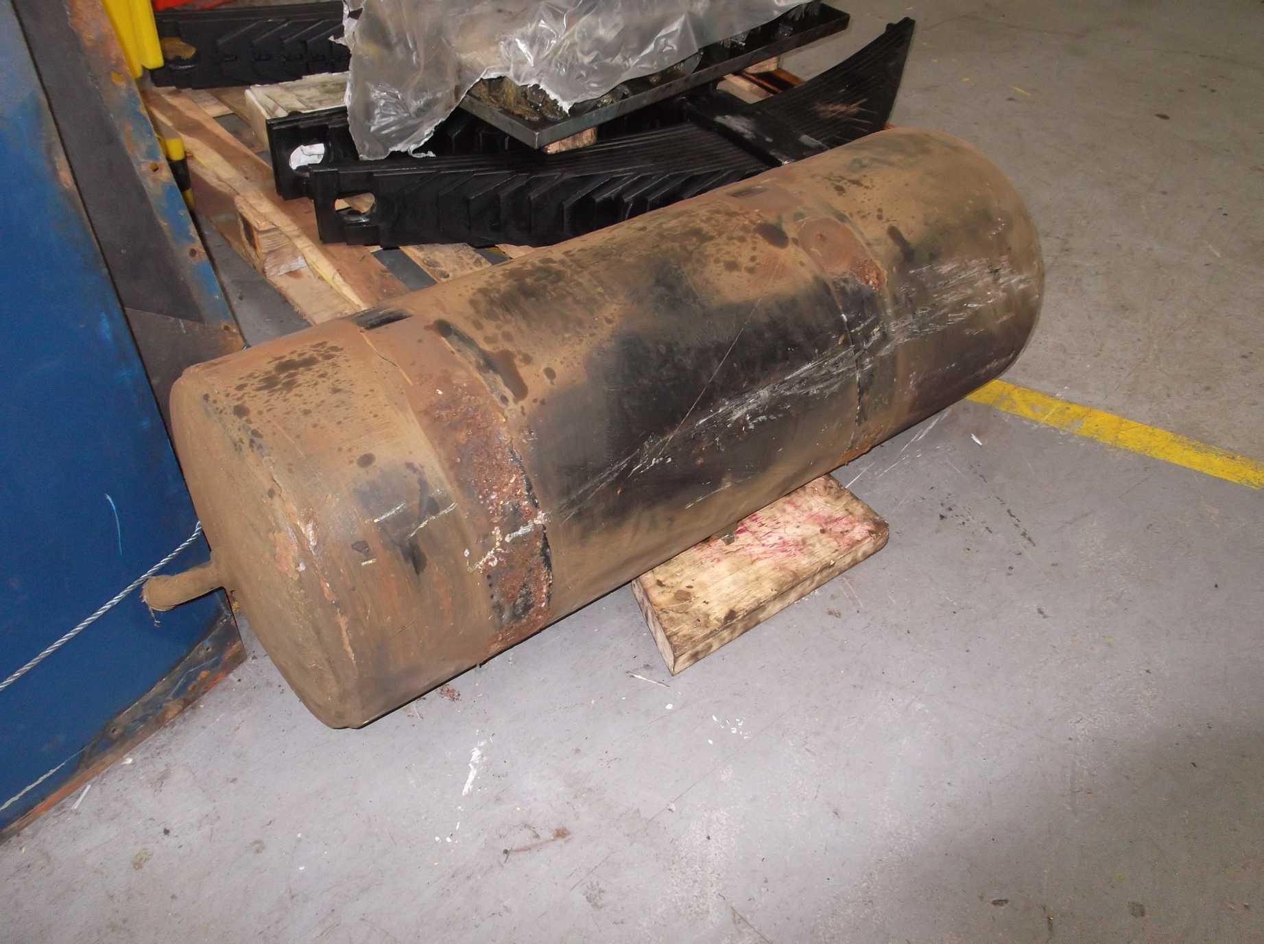
The separation of the tender tank from the frames is complete, but before lifting, a number of items can be taken off the tender. This week the large vacuum tank from behind the rear bufferbeam and further water filler pipes were removed. These filler pipes are again at the rear of the tender frames. One collapsed when attempting to remove it and will now have to be cut off. The tender vestibule bellows has been separated from the tender tank and the vestibule end plate is being prepared for removal.
The tender handbrake handle, removed last week was thoroughly descaled, dismantled and examined this week. There is some wastage to the shaft where it passes through the floor of the tender and the threads at the lower end where the brake is pulled on are worn.
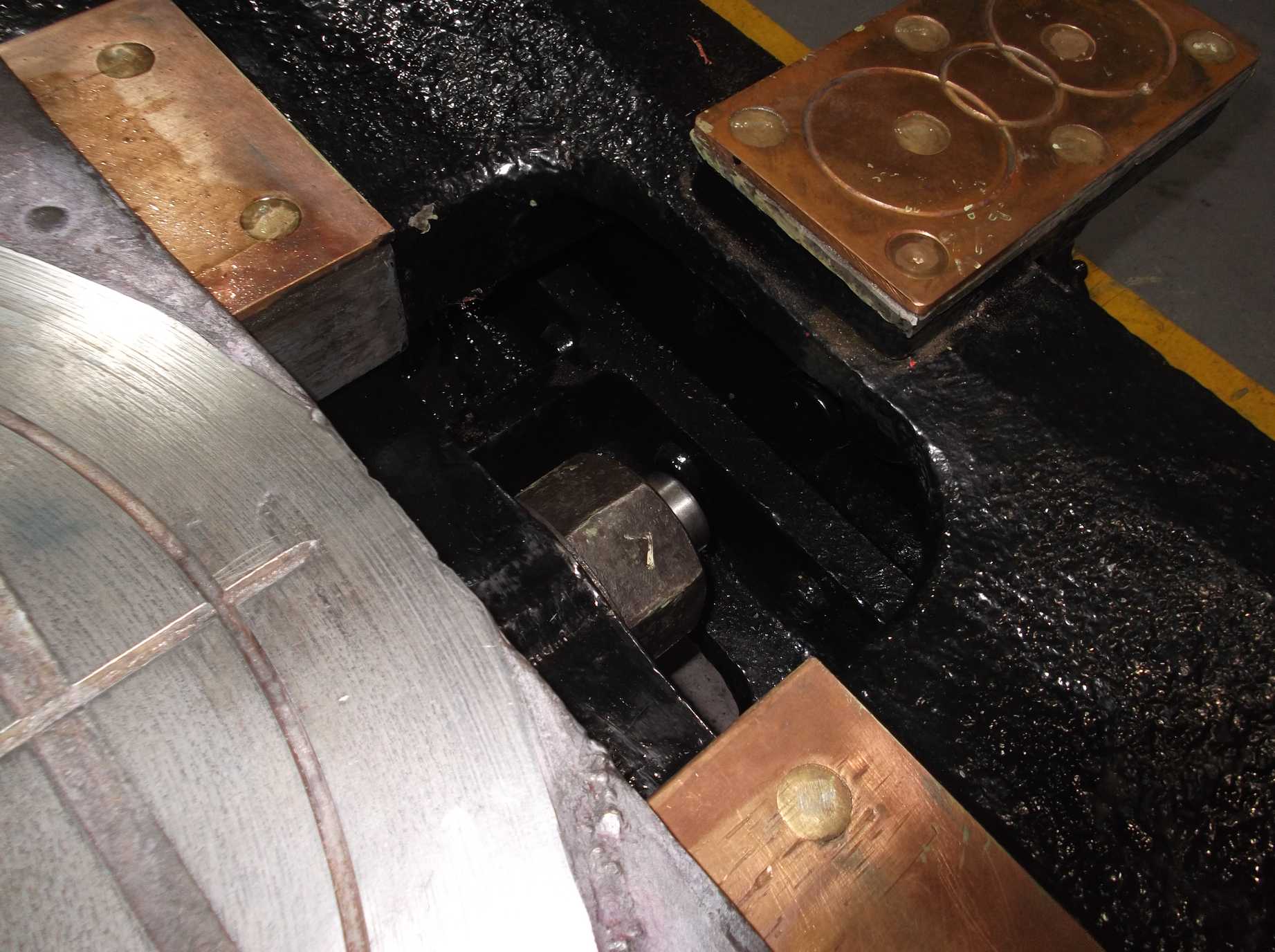
The bogie side control bolts were given a knock to ensure tightness before the fitting of their cotters. The left hand cotter was fitted this week but a new washer is required for the right side to ensue good contact between it’s cotter and the top of the side control bolt nut.
The reversing shaft is fitted with a spiral spring, mentioned in previous reports. It’s a very tight fit on the shaft so it has required careful planning before we attempt to fit it inside the frames. Some wedges and a sleeve have been made so that the spring can be slid up the wedges over the machined square on the end of the shaft. Then the spring will be on a thin tube to slide along the shaft. A fitting attempt will be made soon.
A considerable amount of time has been spent on cleaning the returned wheelsets this week to prepare for filling and painting with most Engineering Team members taking a turn.
Further pipework fitting has been done between the engine frames this week with existing brackets being examined and where required re-welded securely in position.
With the repairs to the front lower streamlining securing holes complete the streamlining was reattached this week. This allowed the refitting of the front buffers complete with new rubber springs.
The failed clackbox castings were retrieved from contractors who had done the initial machining and pressure test. The failed castings are now with the patterns and it is planned to send them back to the foundry in the next week.
Week commencing 25 September
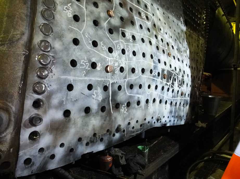
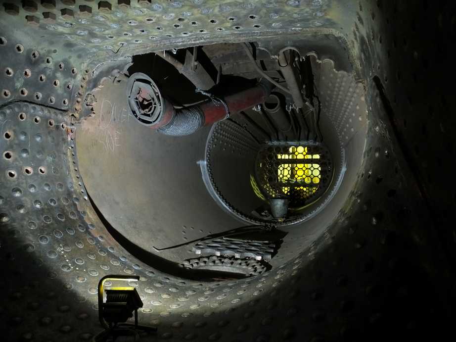
The new boiler side sheets should now be fully stayed, with the last 20 stays planned for fitting this week. With this complete, plans are now being made to turn the boiler onto its side so that the combustion chamber copper welding can be continued up the sides and eventually across the roof plate.
A great deal of effort has been put into getting the wheels in a suitable condition for painting, with most of the volunteer Engineering Team members putting in the elbow grease. By the end of the week they were approaching the condition in which they left York. Paint was finally applied on Thursday to tyre edges after our painter declared them clean and rust-free enough.
Further preparations for the tender tank lift were made this week with the removal of the gangway bellows. The bellows are between the tender vestibule and the large plate that buffers against the coach connection. The plate is thick steel and is very heavy so had to be removed after some careful planning. It was lowered on to the buffer stops behind the tender and was later put to the side and tied up. The strips that hold the cover sheet were removed so that the damaged cover sheet could be removed.
The last water pipe fouling the lift couldn’t be removed with a wrench as it collapsed when we tried, so it was burnt off. After a last look round the tender we couldn’t see anything else that could prevent the lifting of the tank, so packing towers were put in the corners and the tank was jacked. It was jacked a couple of inches and packed against the tender frames.
The last of the new spring hanger bolts were delivered this week and were checked against the drawing by our placement student, who will be with us until summer next year gaining engineering experience as part of his university course. He also measured the hornstay bolts and holes on the bogie frames and is preparing a drawing of the bolts so new ones can be manufactured. The last bogie side control bolt cotter was put in this week, after a new washer was made, to give the cotter a good fit on top of the nut.
The vacuum brake and steam heat pipes were retrieved from store this week. A start has now been made on cleaning and assessing their condition prior to refurbishment and refitting.
The air brake components and electrical equipment removed from the coach returned to York this week after contractor overhaul.
The leading vacuum cylinder centre bearing was taken for weld repair and machining. The repair is now completed and it will be back at York next week for final positioning.
The failed clackbox castings have now been returned to the foundry. Our clackbox valves were taken to the machine shop that will be machining the castings. They have requested these parts to ensure they will be a good fit in the clackbox bodies and that the different sections of the complete clackbox can be separately pressure tested.

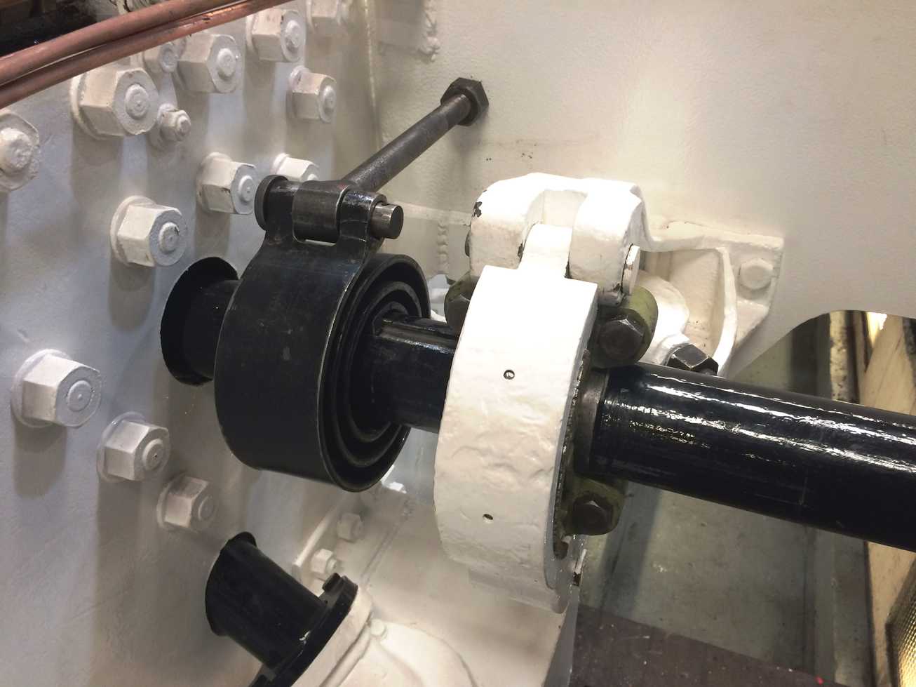
The reversing shaft has now been put back on the loco. As mentioned in previous reports, the shaft has to have the spiral spring fitted as the shaft is passed through the frames. As the spring is a tight fit, a sleeve was made to prevent damage to the shaft. The reverser clutch sheaves were also fitted to the shaft.
This is the 20th update – you can catch up on the previous posts here.