Locomotive Engineer Darrin Crone provides us with an insight into recent weeks’ work on the restoration of the great locomotive.
Week commencing 7 August
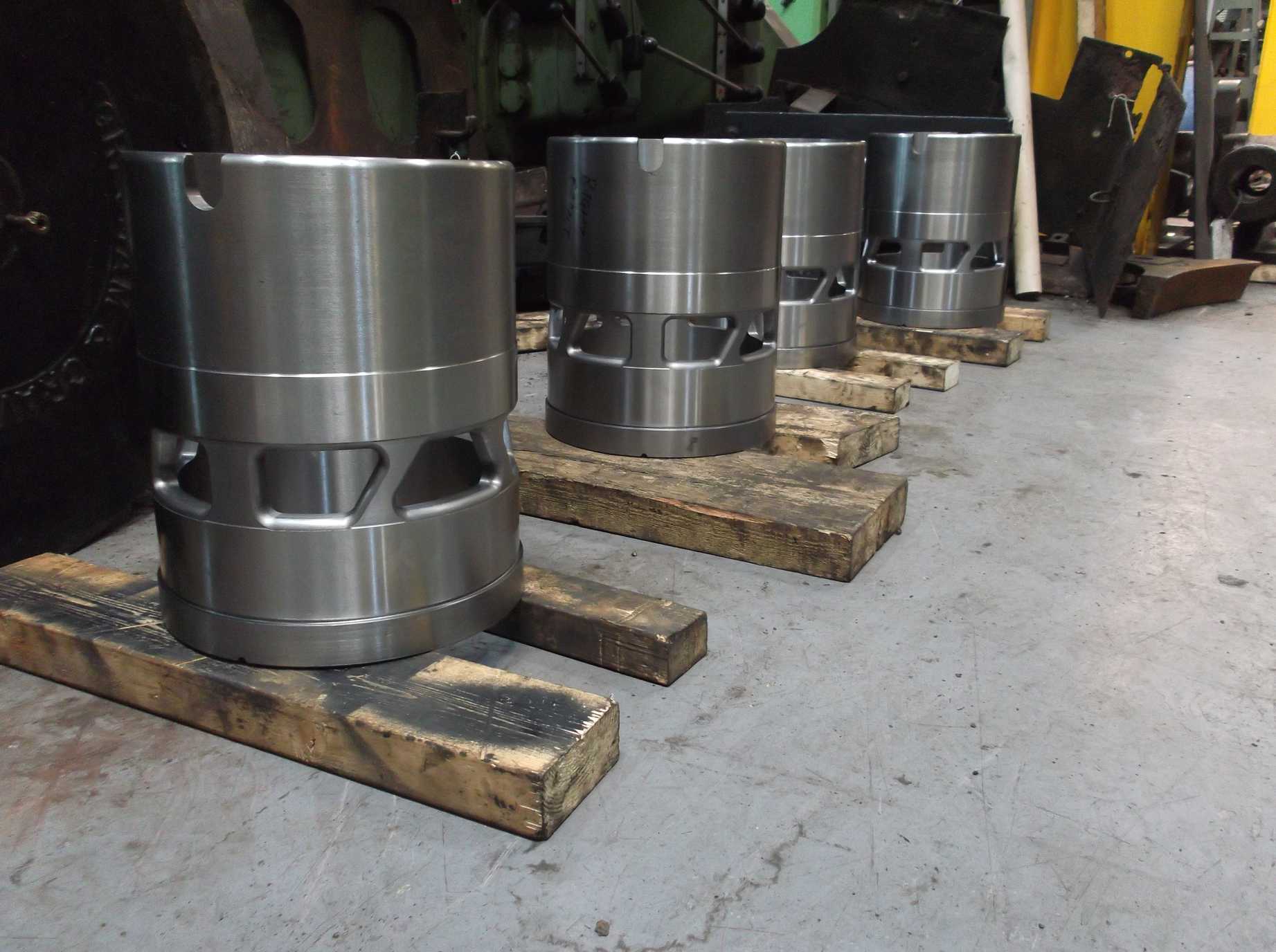
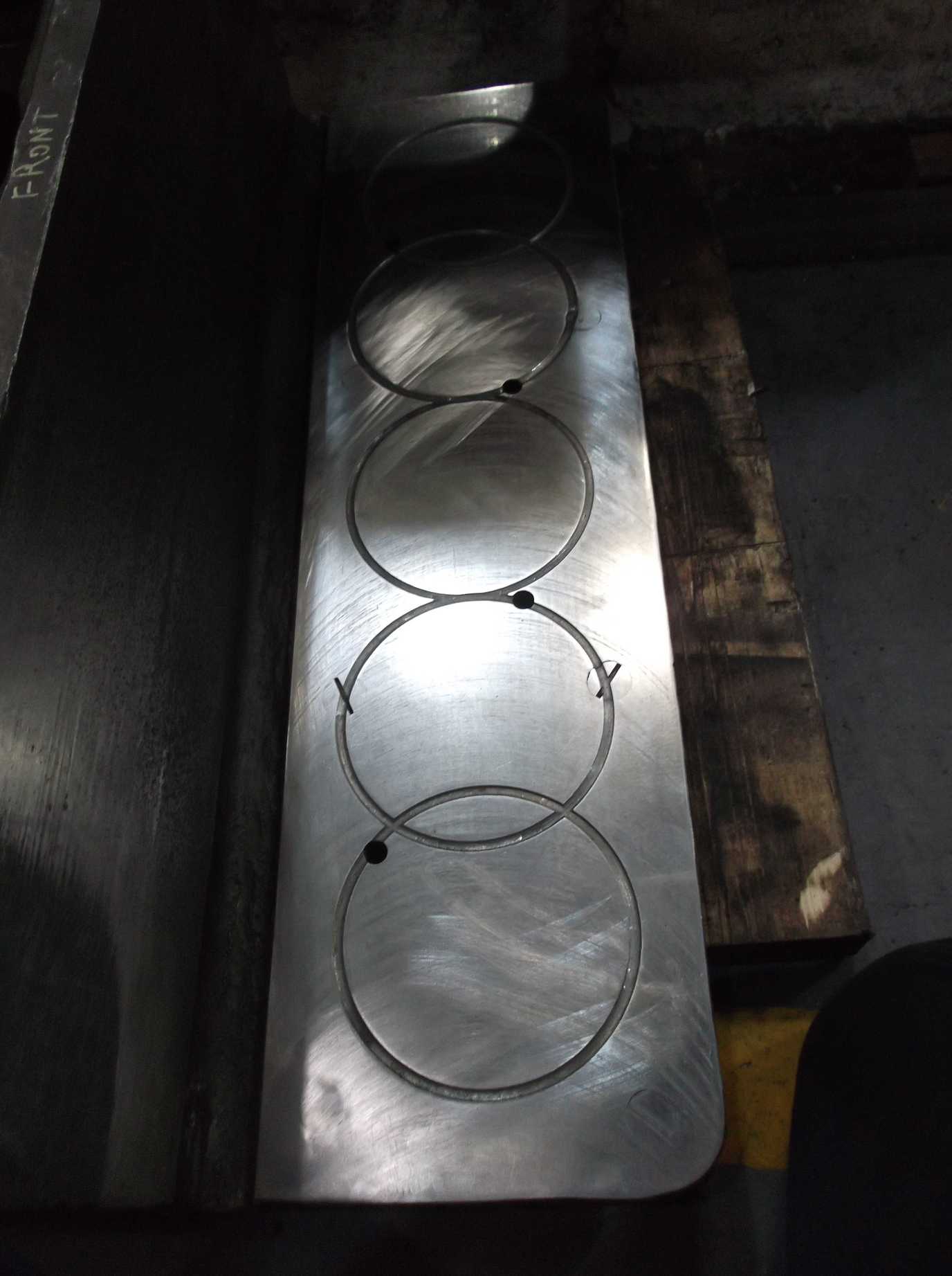
The new valve liners were delivered this week to York from Multitech, and the finish is extremely good. They have now been thoroughly inspected by our Chief Mechanical Engineer, Richard Swales, who confirms that they are spot on to the drawing. We will now organise fitting.
The tender corridor rear window, the port hole, was removed this week, as was the cover over the top of the vestibule that covers the spring that pushes the corridor connection out. The cover was removed as part of the assessment of the tender condition around the vestibule and the water filler space. Inside the corridor further needle gunning and scraping has been carried out to remove paint and bitumastic coatings in the corners and on the floor.
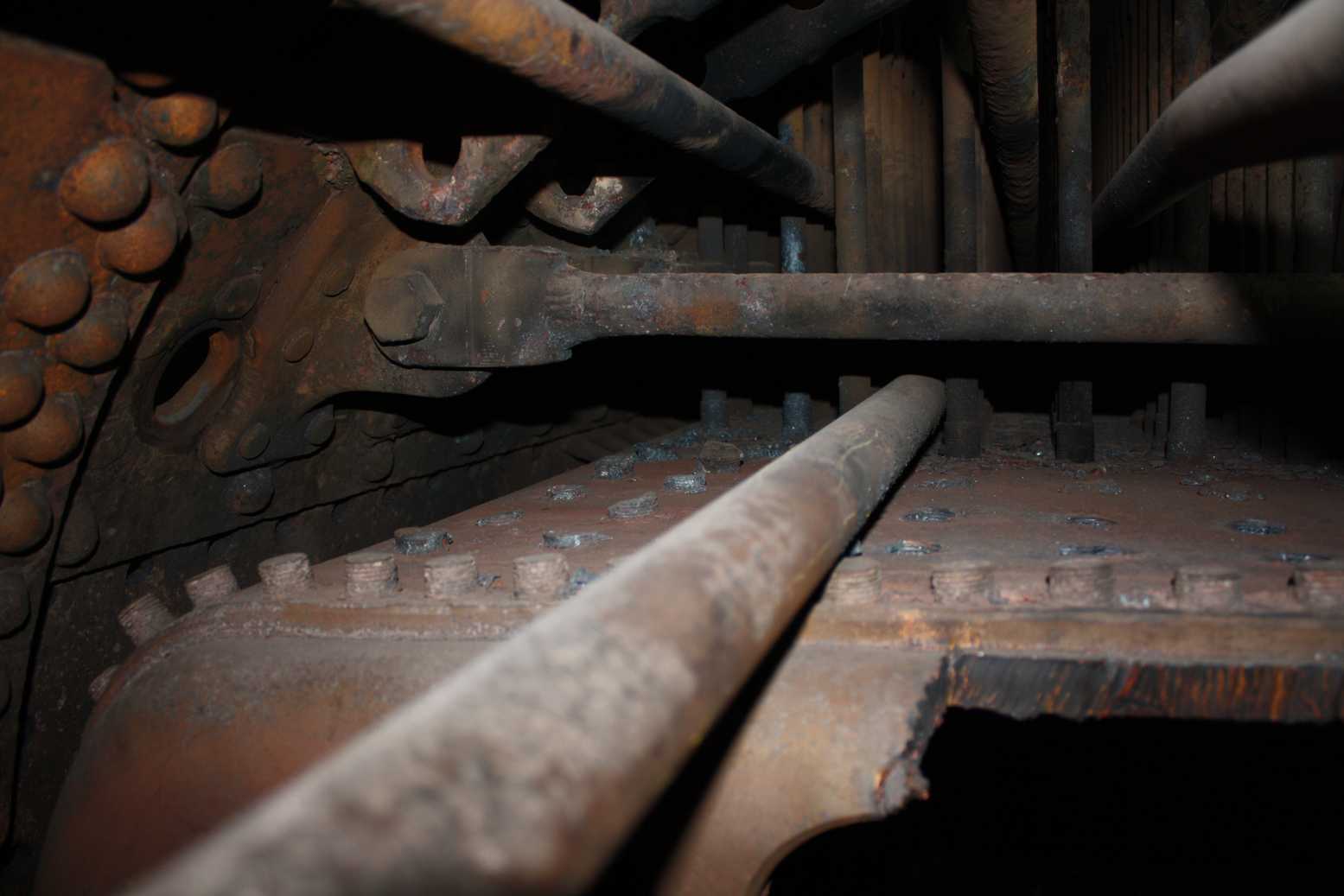
Work was also carried out under the tender. Cleaning between the frames has enabled the various pipe runs and conduit to be marked and a photo survey has been carried out. Now this has been competed, a start has been made on the removal of components that will enable the areas where the tender tank meets the chassis to be viewed and inspected.
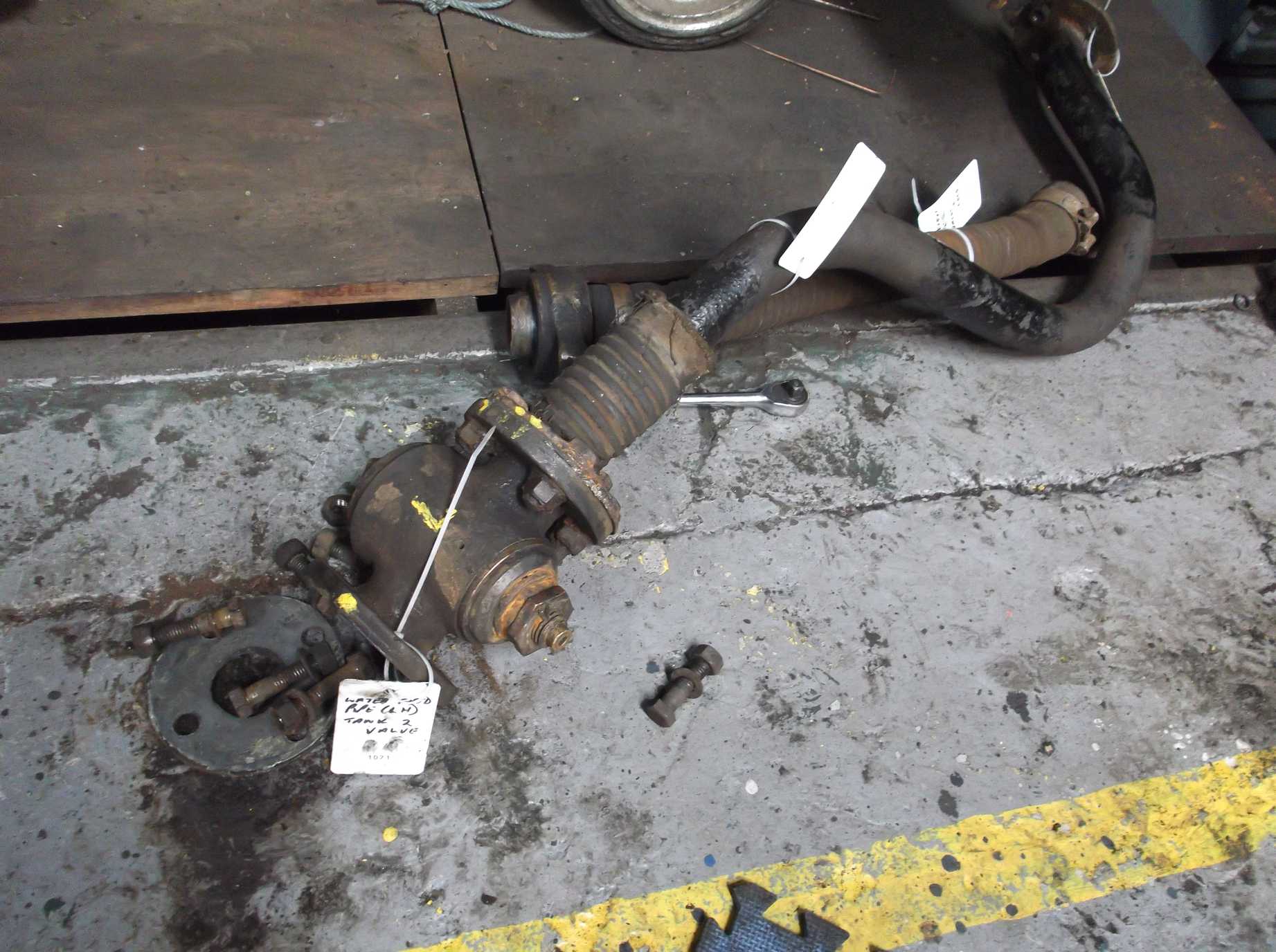
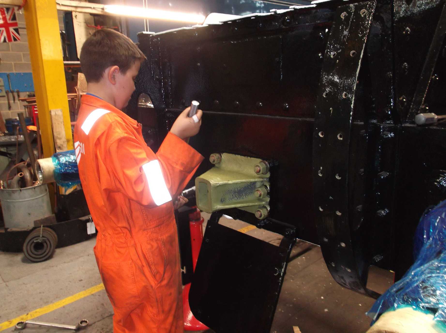
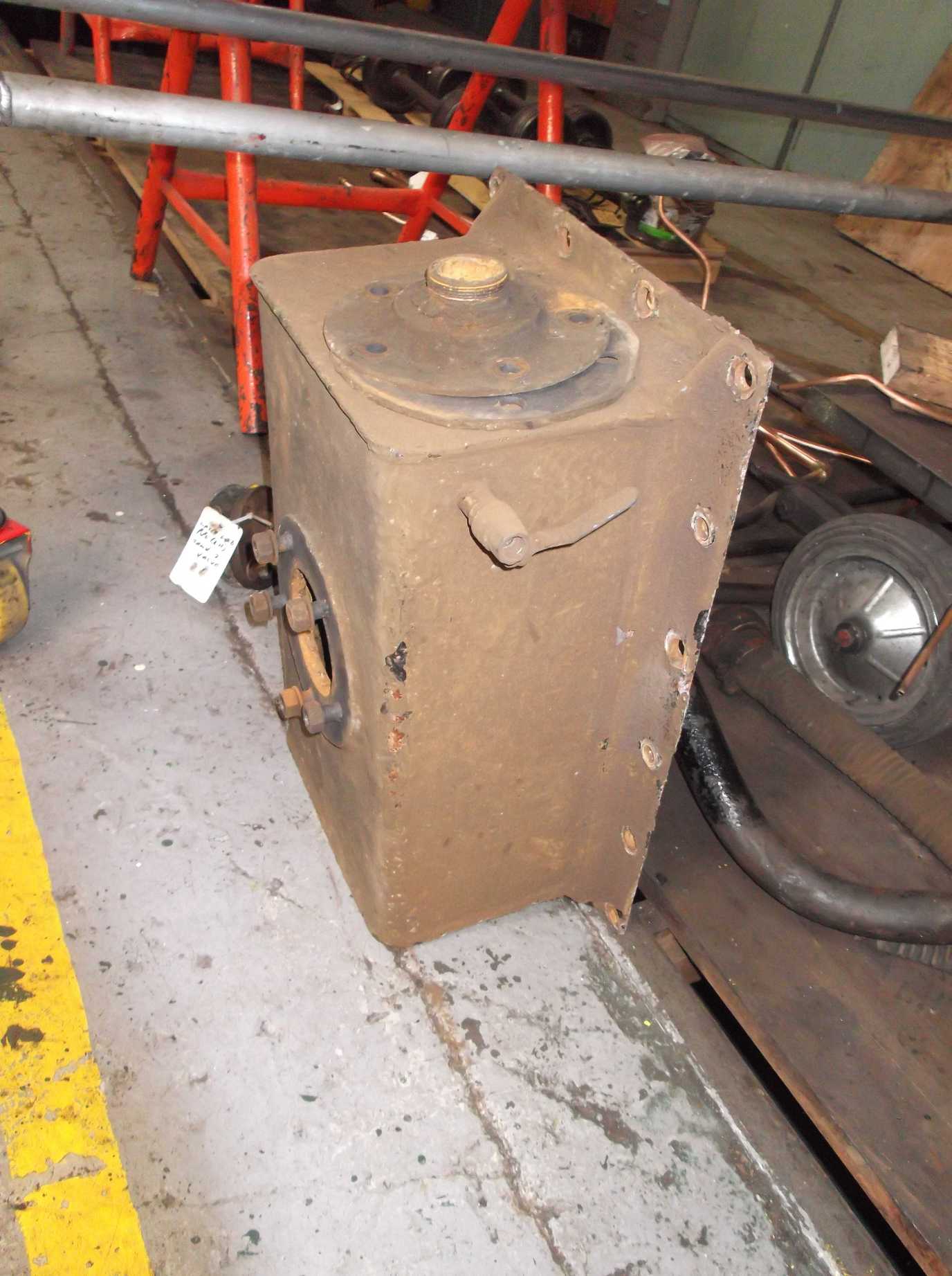
The underneath of the front of the tender is crammed with pipework and brake gear, and the process of removing this has begun. The water feed valves and associated pipework were removed. The 007 Gang of junior volunteers started separating of the water valves from the removed pipework. The water feed is taken from a sump and this is in the form of a box which can be removed. We will remove it so that its condition can be assessed and it will improve air circulation inside the tender. Most of the bolts securing the box have now been removed.
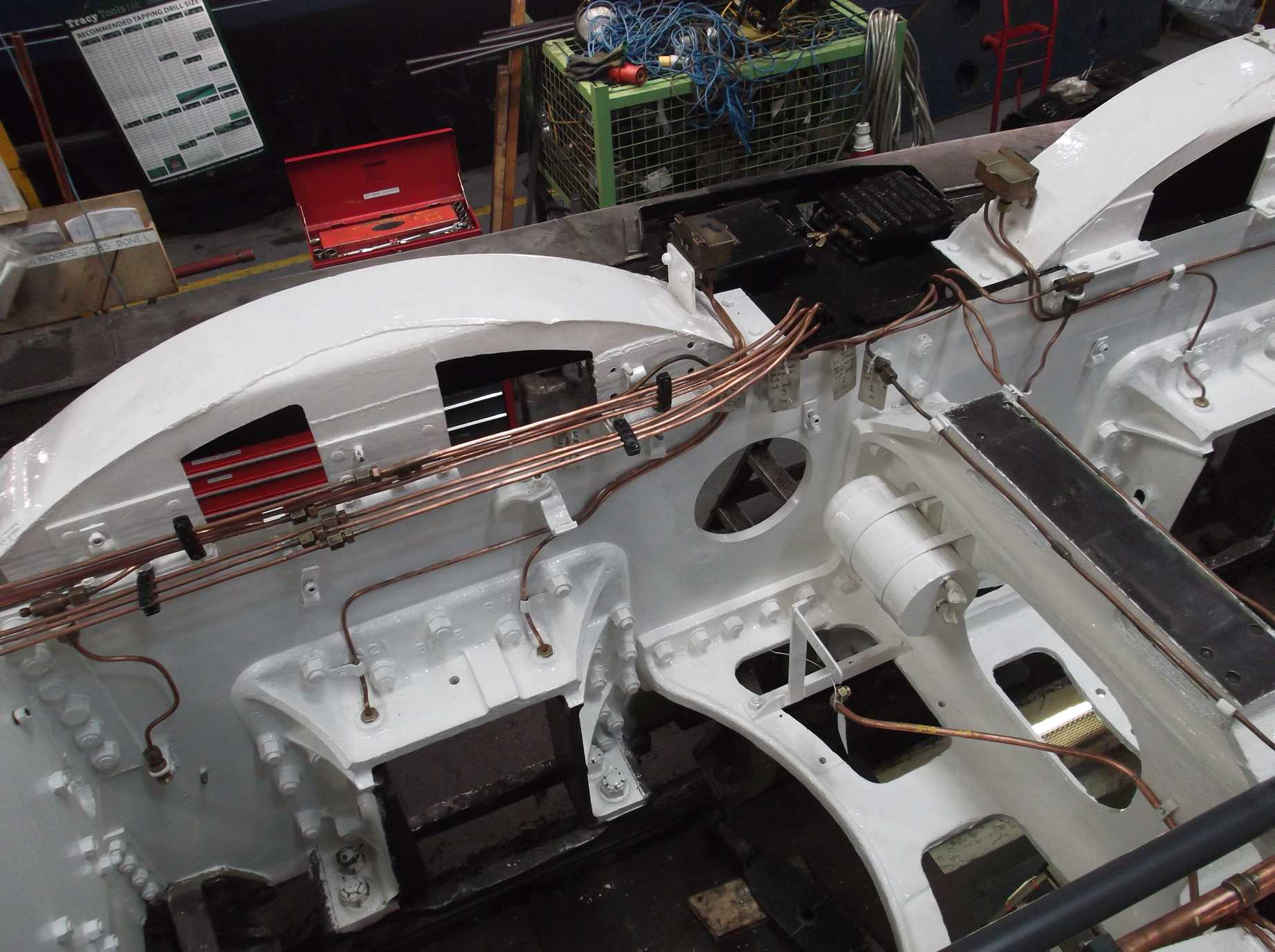
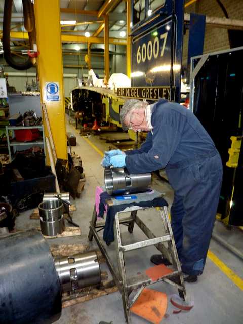
The overhauled cylinder lubricator was returned to York last Saturday and was refitted to the loco this week. After fitting the lubricator, we began fitting the pipework running to the front of the loco.
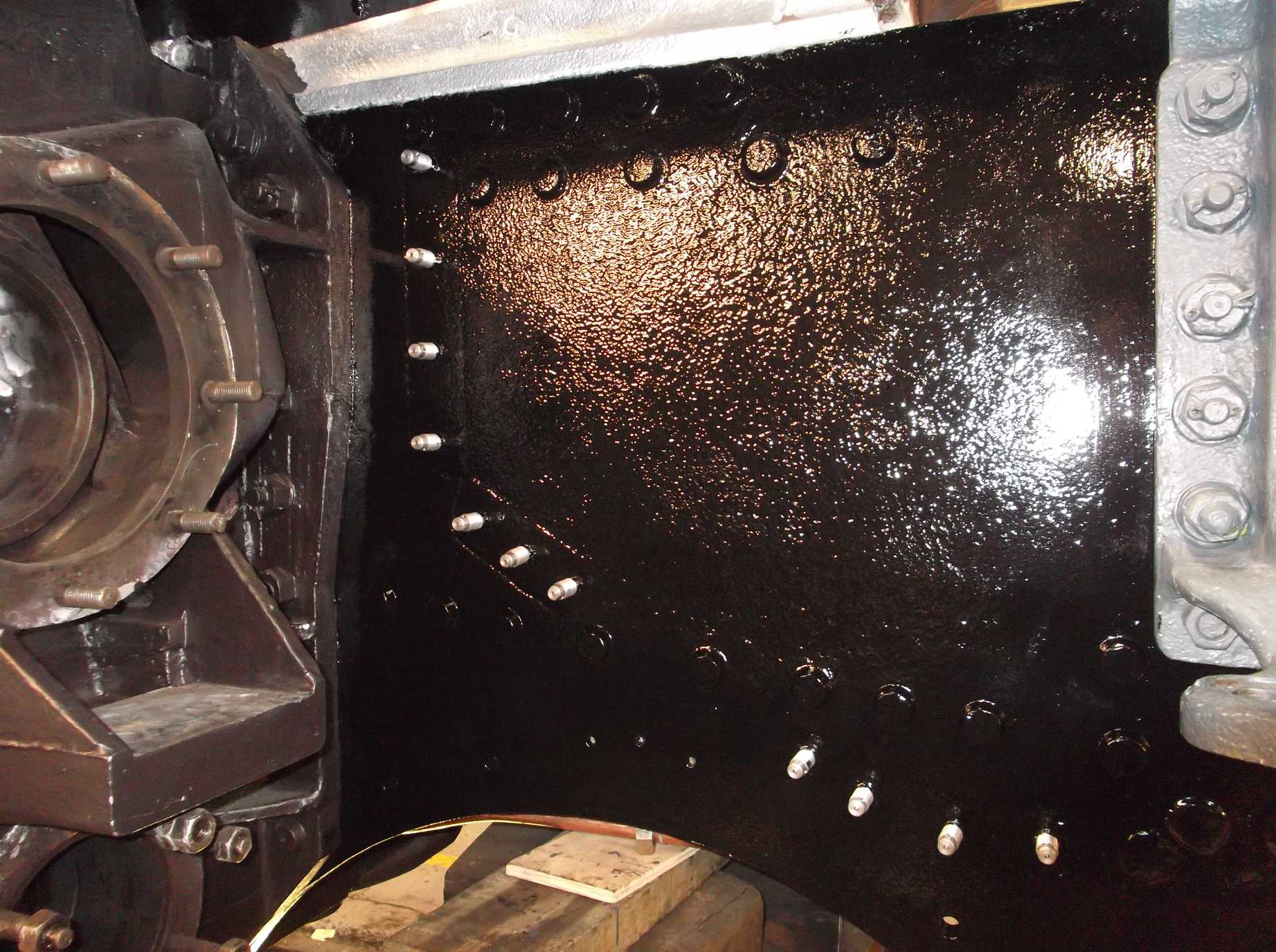
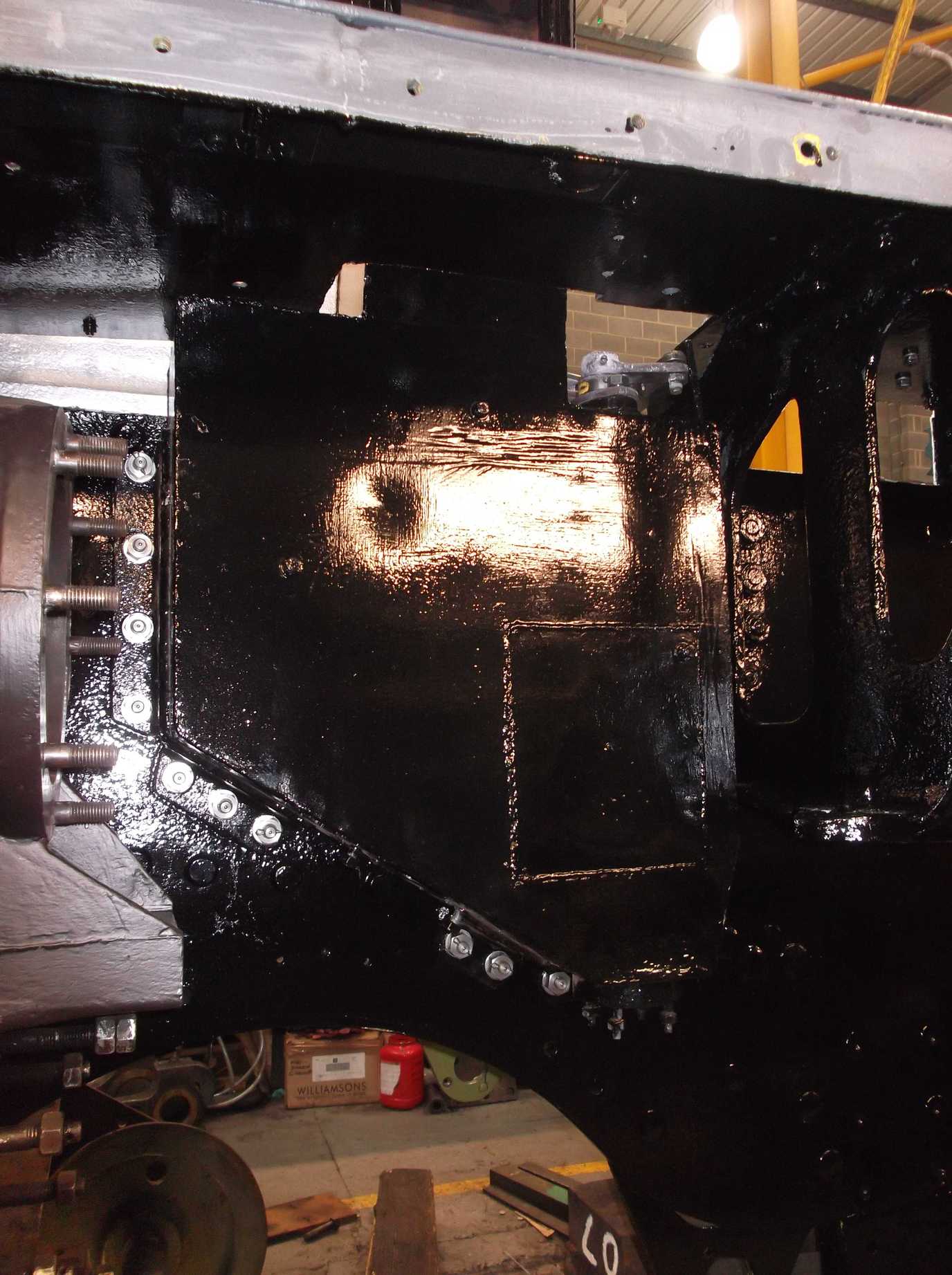
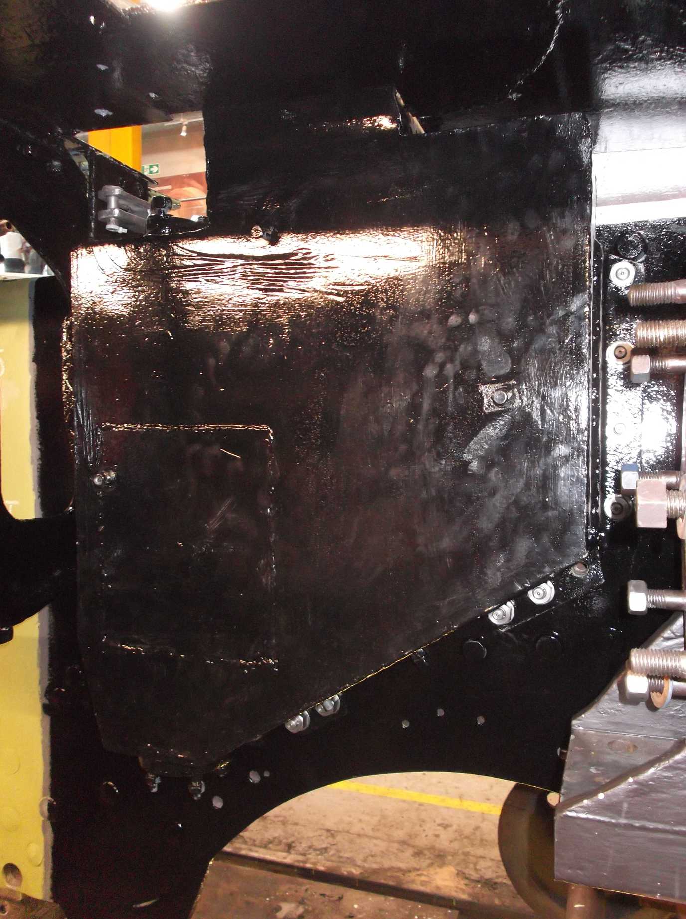
The gravity sandbox studs were refitted to the left side of the frames this week. To enable the sandbox to be refitted, the frames were painted to top coat gloss black on this side.
The bogie centre casting was returned to York this week from machining at contractors. The lower bearing surfaces were polished this week by Engineering Team volunteers. Three of the screws holding the leading bearing plate had come out during machining—not surprising, as the screws are relatively short so there’s not a lot of thread holding them in. New screws were machined and fitted as patch screws. After fitting, the tops of the screws were carefully finished flat with the bearing plate. Two of the screws went across oilways in the plate, so the oilways were re-cut. The centre casting is now ready to be trial fitted to the bogie.
The new plates for the bogie centre casting were welded in place this week. While the welder was with us we also had some welding done to rebuild a small area of wasted plate under the cab.
Work continues around the front of the loco in refurbishing the streamlining securing holes in the footplate angle. All the streamlined screws have been retrieved from store, cleaned and die nutted. Under the centre section of streamlining is the front coupling hook extension casting. This has now been refitted.
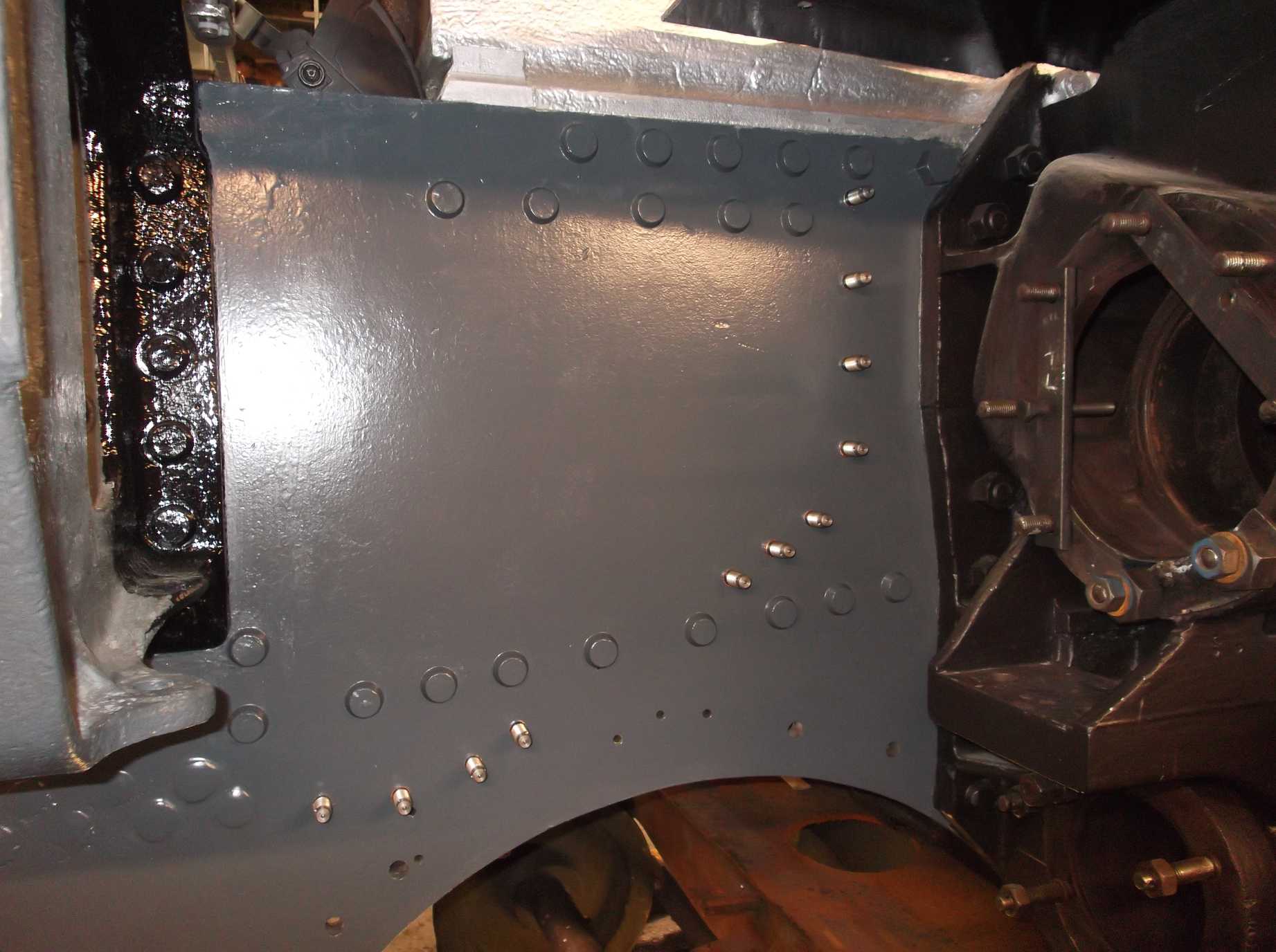
Machining began on the first fitted rivets for the spring brackets this week. The hole sizes have been taken and they have been machined to finished size on diameter but the heads and ends are yet to be machined.
The mud hole doors were finish cleaned and descaled this week. They are now ready to be taken to Llangollen for their overhaul to be completed prior to fitting to the boiler.
The leading loco vacuum cylinders were delivered to contractors this week for refurbishment work to their trunnions. There is evidence of some previous attempts to rebuild the trunnions, which will have to be removed before they can be re-sleeved to the BR drawing.
Week commencing 14 August
It is planned for the coach to go to external contractors for overhaul. We use the coach for storage, though not for loco parts which are stored elsewhere—we moved some stores back to Grosmont when we transported the axleboxes. The process continued this week when we moved a storage cupboard from the coach to the workshop and filled it with stores. There is still stuff to move and another trip to our Grosmont storage facility looks likely.
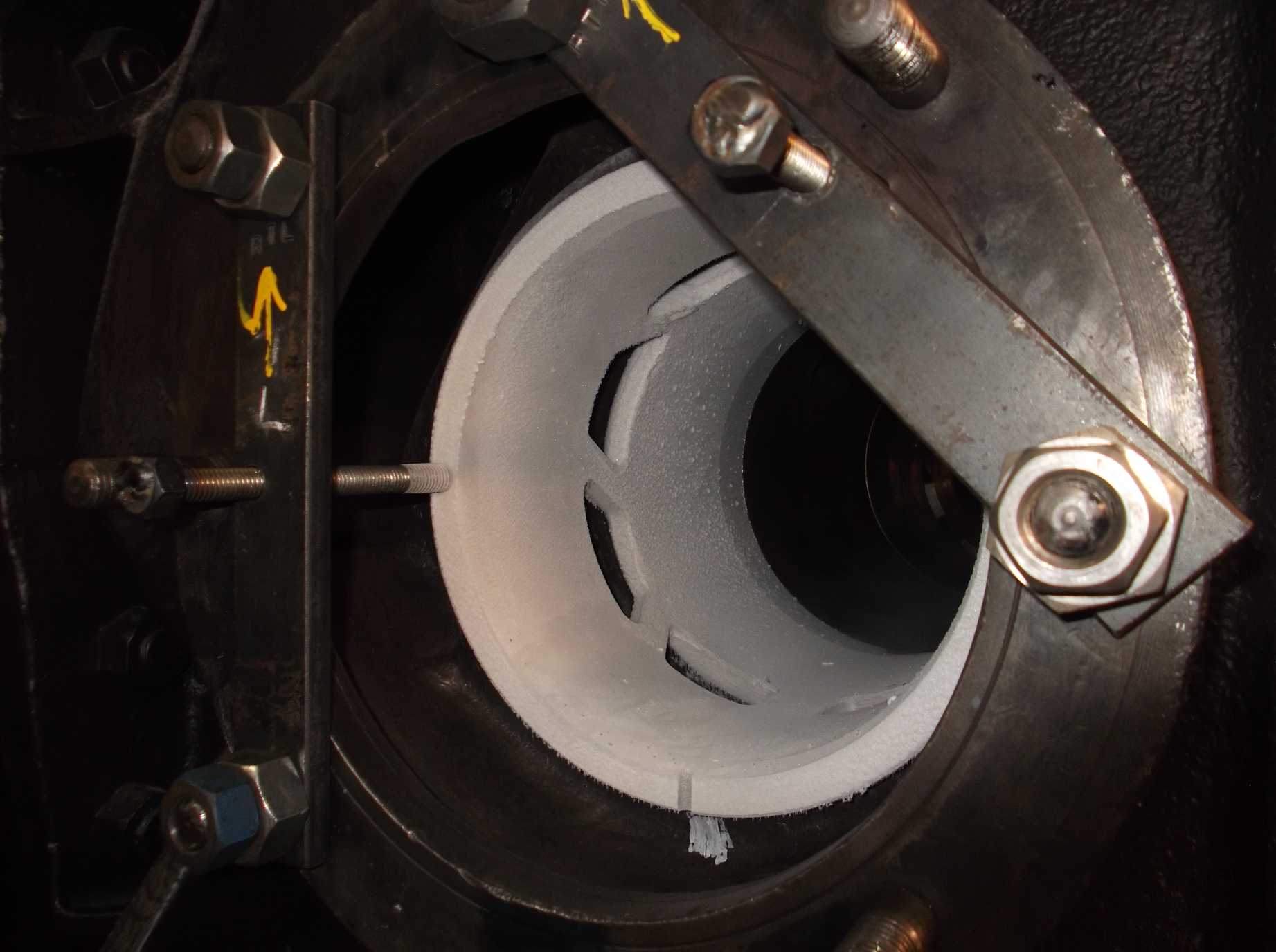
We plan to fit the valve liners next week so preparations for this have begun. We have made up some plates to allow the liners to be clamped in place. These fit over the studs in the steam chest castings. There are a number of different types as the outside cylinder stud spacing is different from the middle leading, and that is different from the middle trailing.
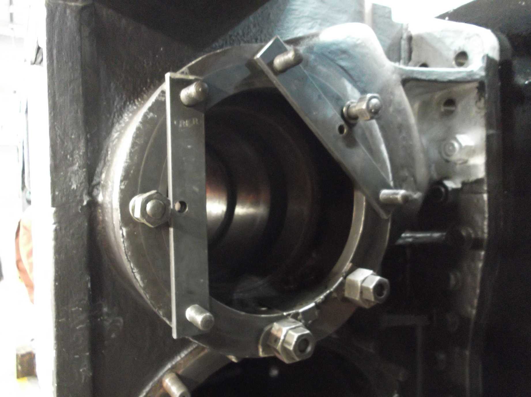
The valve liners have an orientation, which is indicated by a groove machined in their outside edge, and this must be vertical when finally located. To assist with this, small plates have been made that point along the bottom centre line of the steam chest. In addition, a tool has been made that locates in the grooves in the liner and allows it to be rotated in to position.

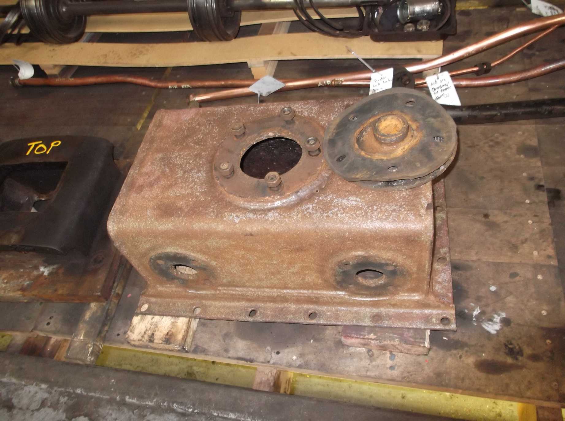
The tender sump was removed this week. A large filter box is fastened above the sump that prevents solids from entering the feedwater. The last bolts were removed from the sump and it was removed, and this also released the filter. The gasket and silicon sealant sealing the assembly has now all been scraped off.
The leading (gravity) left sandbox was put up this week on new studs. The sandbox came off a lot easier than it went back on, as some of the original studs came out with their nuts. To get the sandbox back on a number of studs had to be removed and all are now back in place. A start has been made on fitting the right-hand studs, but the sandbox will not be put on the loco until the new valve liners are in.
The operating mechanism for the leading sands was put up this week. A new gasket was cut for the left-hand sandbox and the fit of the pins in the mechanism is being assessed.
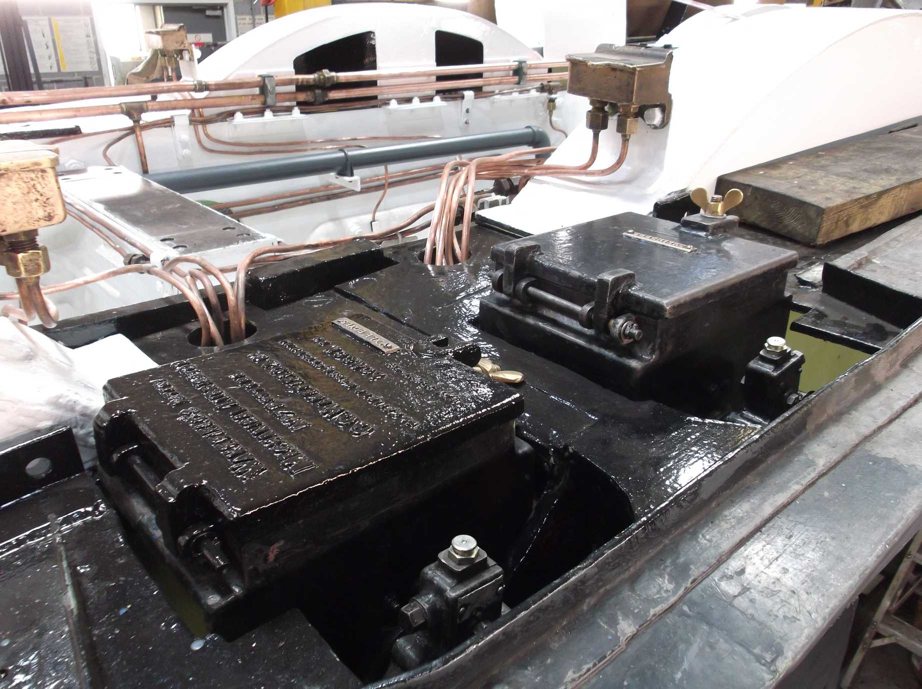
All the fittings from the air brake valves that will be going for contractor overhaul have been removed, and the valves are now ready for delivery to the contractors.
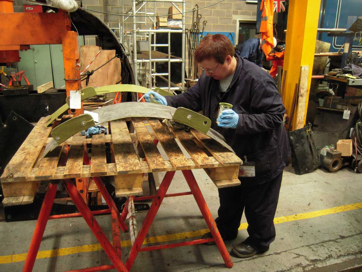
When the leading sandboxes are in place, the trailing bogie splashers can be fastened to the loco. This week the spalshers were stripped and inspected. As with many of the thin sectioned parts of the loco they show their age with wear and cracks. One of the splashers was cracked from wear apparently from contact with a leading sandpipe. The crack was welded up and another area of wear rebuilt and dressed. The splashers were given a final clean and have received a coat of primer.
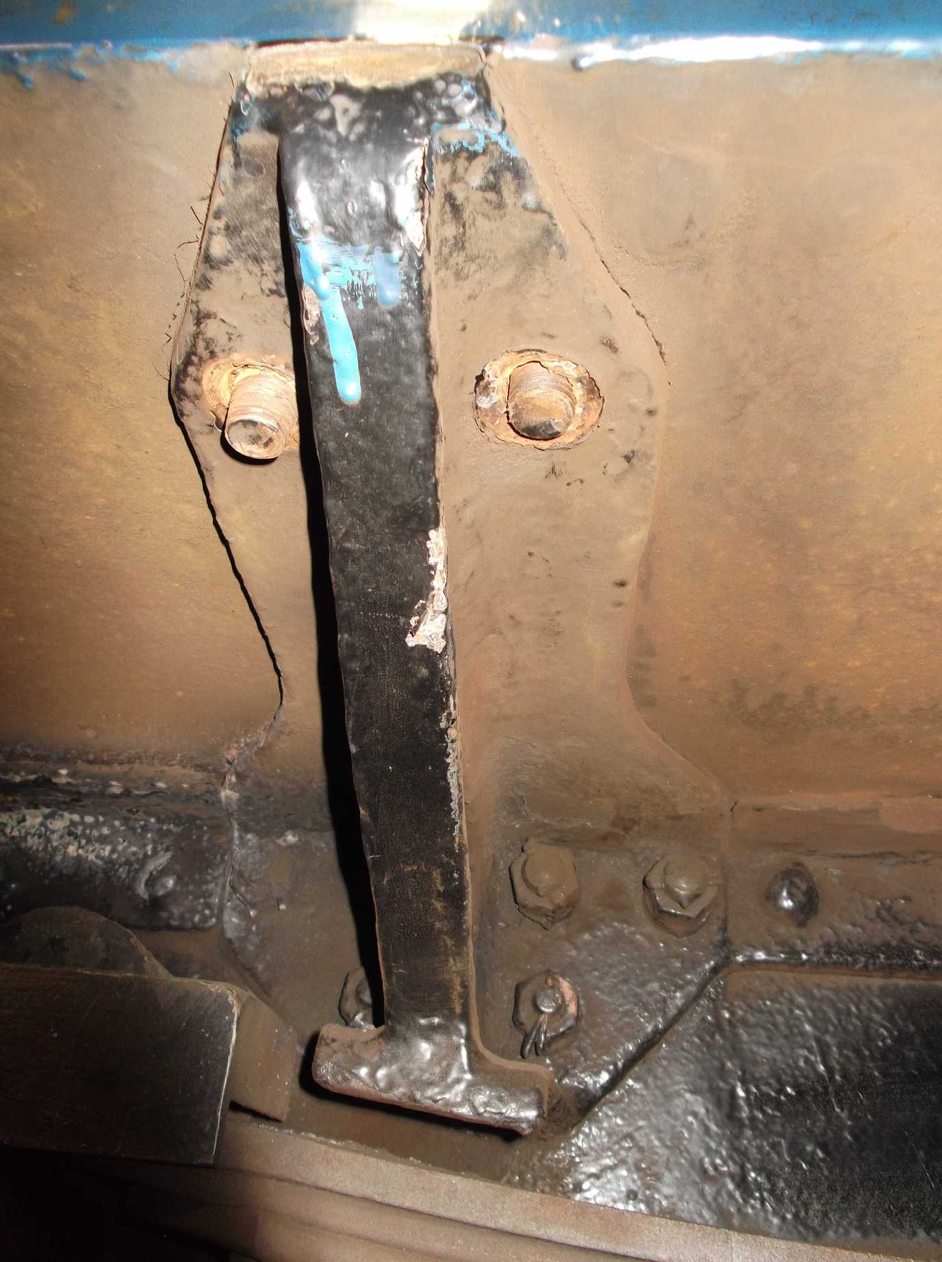
At the rear of the loco frames the damper operating linkage bracket is secured with bolts to the frames. The bolts are wasted so it has been decided to replace them. As this area of the loco has suffered corrosion, this is easier said than done.
Further work has been carried out on routing the cylinder lubricating pipework across the middle slidebar stretcher. Further work has also been done on the airbrake pipework that goes between the ashpan and Cartazzi.
On Saturday the riveting team was assembled again and good progress was made. The remaining front brake cylinder stretcher rivets have been put in. The team then went on to put the first three rivets into the spring brackets, starting on the left side of the frames. The rivets were specially machined to fit in this location. They went in nice and tight, as demonstrated by the next rivet in the row becoming slack. This was removed and will have to be replaced.
Week commencing 21 August
The air brake valves were delivered to contractors this week for overhaul. We have discussed with the contractors the order in which the valves should be refurbished as some parts, especially the DV2 valve located between the frames, could do with fitting before the boiler. The fitting of the DV2 valve also allows the pipe runs from it to be installed.
The clackbox castings and patterns have been collected from the South Lincs Foundry. The patterns were returned to their owners and the castings delivered to the machine shop in Darlington. They will be part-machined to allow pressure testing of the castings to prove they are free of flaws. They will then be finish machined. The internal parts have been refurbished or replaced already so we’re only waiting for the clackbox bodies to be completed before the units can be assembled and subjected to final pressure testing.
The front corner streamlining fixing hole refurbishment was continued this week. Only a couple of the more awkward ones to complete now. The new studs for the regulator stuffing box were received this week and have now been fitted.
The rivet made loose during the fitting of the three last week was also removed. Its hole has now been reamed and measured and is now ready to receive a new rivet.
The bogie splashers that were repaired last week have now received gloss top coats. The mounting bolts have been die nutted and cleaned and a start has been made in the preparation of the bogie cover plates for fitting.
We made good progress this week on the separation of the tender tank from the tender frames. Most of the nuts have been removed from the bolts holding the tank down. There are some still to remove in less accessible locations around the dragbox and tight up against the frames under the tank.
The sump removed from the tender was needle gunned this week to remove corrosion, scaling and traces of the old tank coating. There is an area that has wasted quite badly and there is a hole, which had been covered by the tender internal coating and will require repair before refitting.
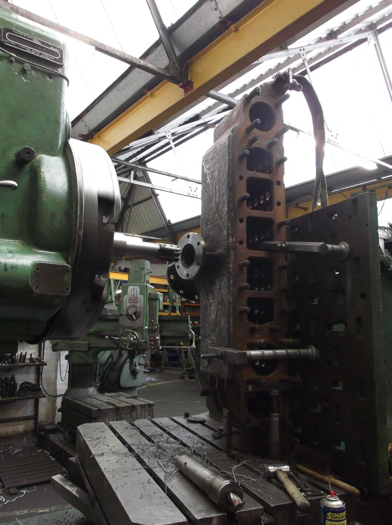
The main task of the week was the fitting the new valve liners. The preparation included cleaning the steam chests and some final deburring of the liners. The fitters from Multi-Tech turned up promptly on Thursday morning, closely followed by the contractor with the liquid nitrogen. The procedure is that the liners are chilled in the liquid nitrogen to approximately -200C. This shrinks them, and they are then fitted while cold and when they return to ambient temperature they are an interference fit.
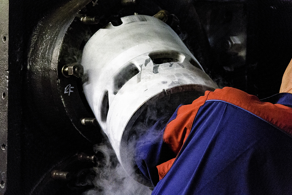
The liner fitting went very much to plan, with the tool we made last week used to accurately align them. The clamps we made were used to fix them in place so that there was no movement while the liners were warming. Extra-long clamp screws were made earlier in the week from studding.
After the fitting of the liners the Engineering Team volunteers didn’t waste any time and the right-hand leading sandbox was put up on the frames.
This is the 19th update – you can catch up on the previous posts here.
I just love reading these reports, just like reading good novel, keep em coming. You guys are doing a fantastic job.