WEEK COMMENCING 4 February 2019
The vacuum reservoir cylinder that is mounted under the tender trailing dragbox has now received coats of paint. When it was being moved about it was clear that there was a fair amount of loose scale in the tank so the tank was upended and shaken and a fair amount of debris was got out of it. The surface where the mounting straps hold the tank showed pitting, nothing too serious but they have been filled and painted over which will minimise corrosion in the future.
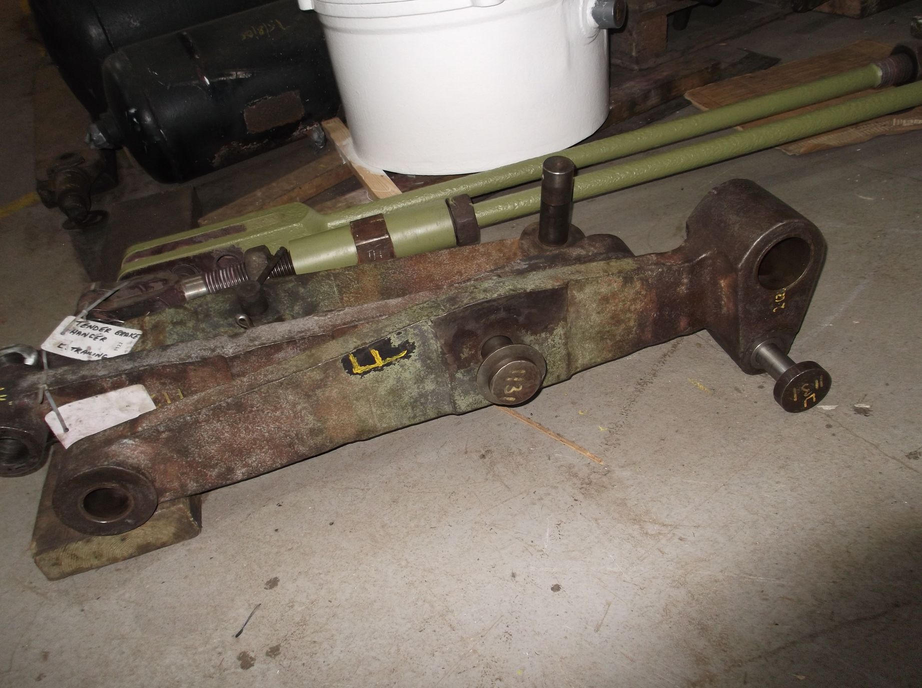
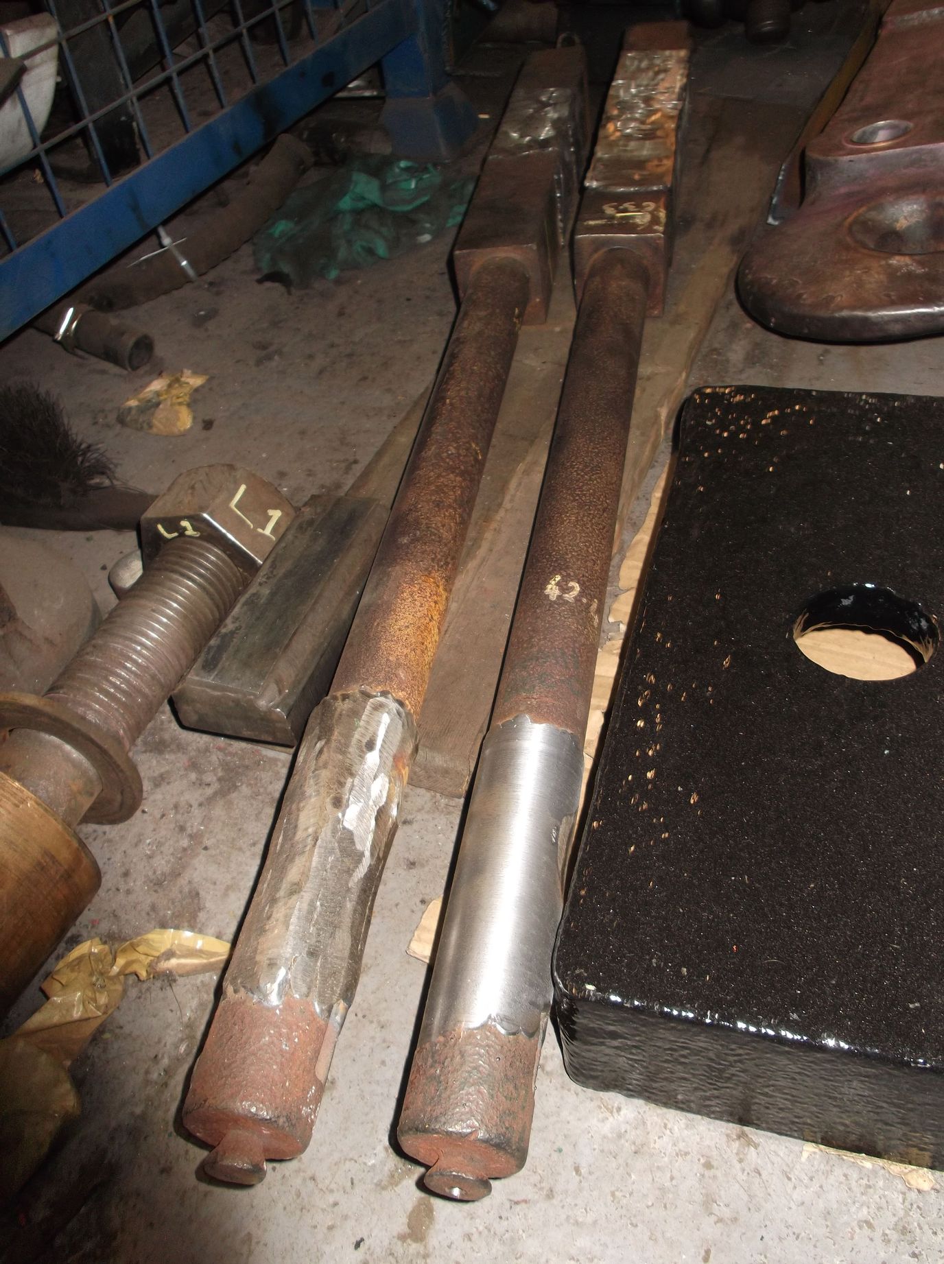
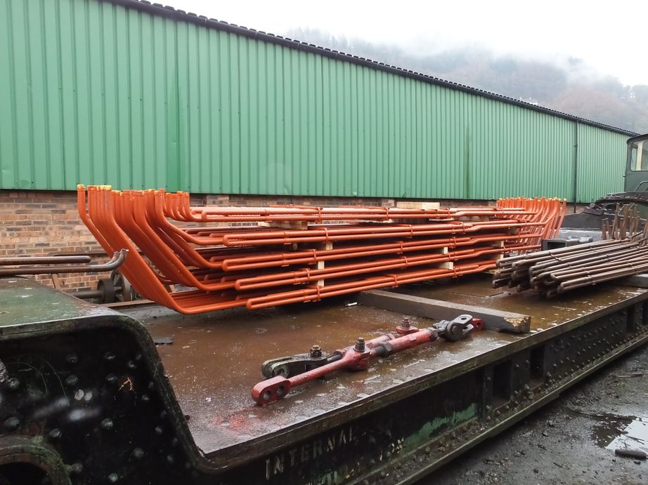
On Tuesday a group of us went over to the National Railway Museum store and we received a full set of tender brake hangers. These are substantial forgings and look to be unused. These have been gifted by the museum to us and will be put in our store for possible future use. Meanwhile work on the refurbishment of the existing hangers is ongoing. This week the lower end holes have been drilled out on the large Archdale drill. Some were already bushed but all show wear. They will all now be bushed. The corresponding pins are being recovered by skimming to a common size. Most have cleaned up well though not all and those that do not will be scrapped.
The tender spring hangers are being worked through, dressing any damage they have picked up and cleaning out the threads and nuts prior to evaluation.
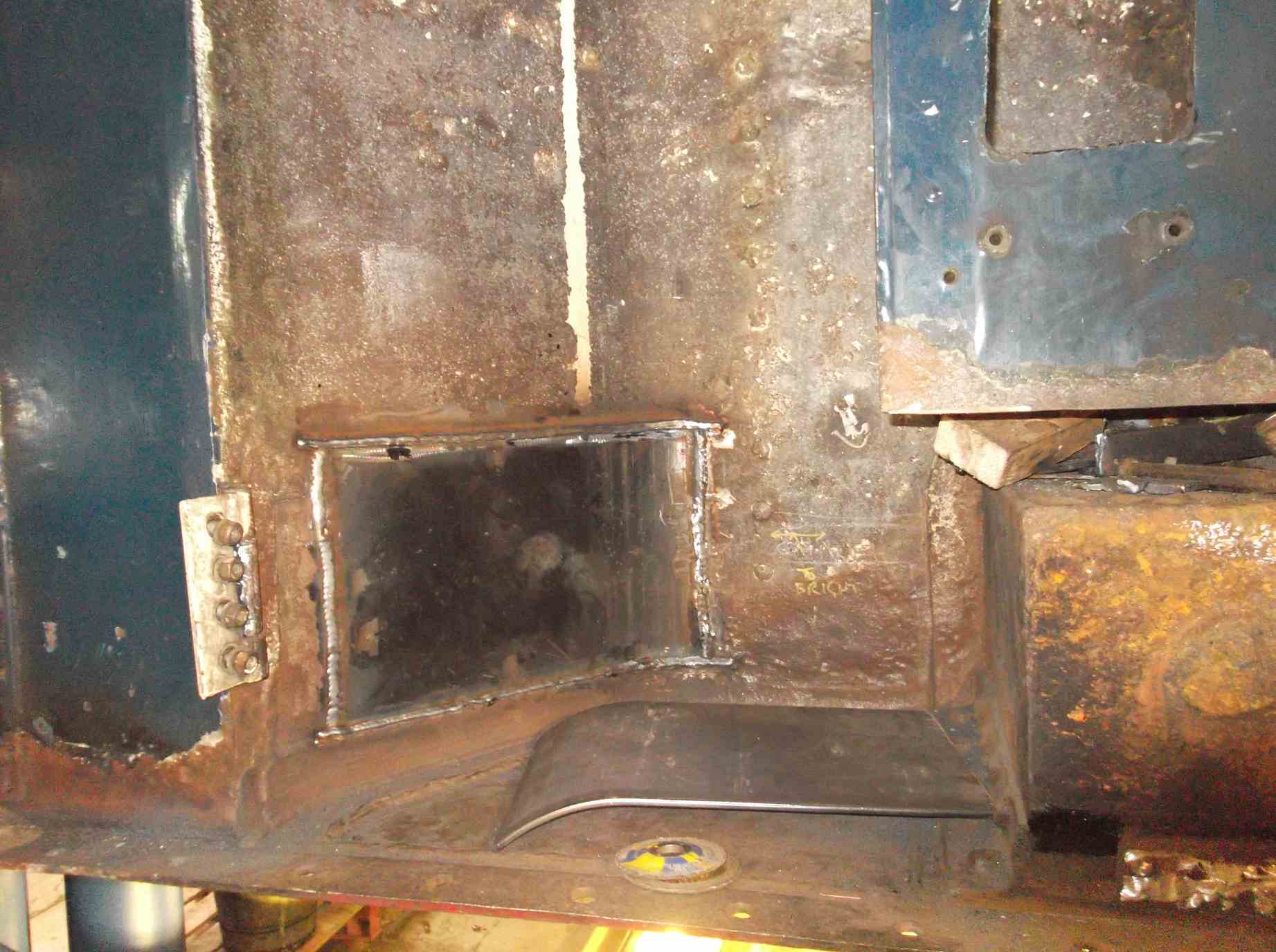
The last two drain cocks have been successfully pressure tested. This has turned in to quite a saga and we had reached the point where we were going to get new housings cast, however we have managed to recover the last two just before being consigned to the scrap bin. Just to recap, most of the valve bodies had heavy wear from the operating rods. The area of wear was built up with braze or bronze weld. The slots for the operating rods were then dressed and valves and rods tried in place on the loco and operation was good. Then when we pressure tested them a number leaked, we think due to previous leak paths being uncovered by the heat of the brazing. The leaks were then traced, the surfaces prepped and silver soldered. However, we now don’t have access to acetylene so had to use propane which requires much more gas, so there is much more blow tending to blow the silver solder from where it is needed. Great care and patience is needed but it has saved us a lot of money and work in not having to get new castings.
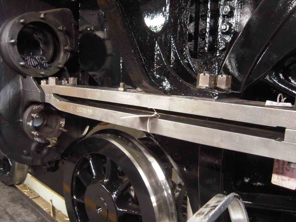
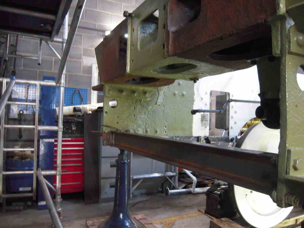
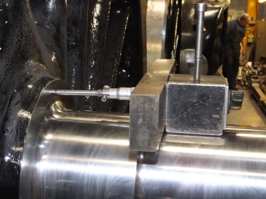
The lower slidebars are now being put up so that the distances between the bars where the crossheads slide can be measured.
Repair work to the tender tank continues. New steel is now at York that will allow us to replace a large section at the rear top of the tank. We also now have steel profiles and rolled to shape sections for the top of the vestibule. The internal drain pipes and the hydrant filler pipe have been hammer tested and they all seem to be sound, though a new joint for the filler pipe will be required against the bottom of the tank.
The scraping of the left trailing axlebox is nearly complete. One more rub on the blue and that should be it.
The pipe fitting team have installed a platform in front of the cab, across the top of the loco frames to access the steam sands pipework that runs down the front of the reverser column. This pipe is now being formed, the old pipe has been scrapped. The platform will also allow progress on a number of pipe runs including the OTMR sensor pipes.
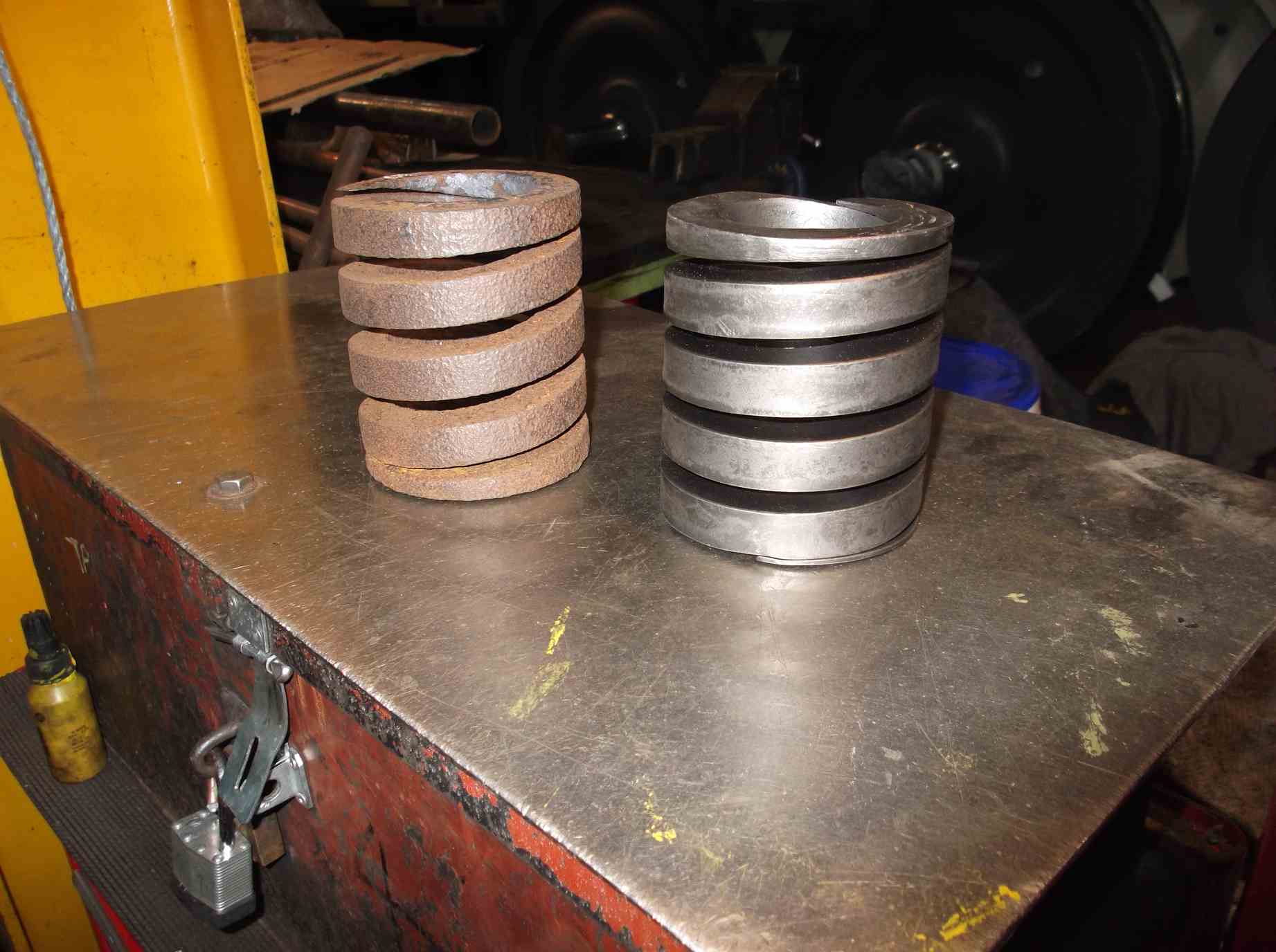
The new safety valve springs are now at York. They have been checked dimensionally and will be fitted to the safety valves before being sent to Llangollen.
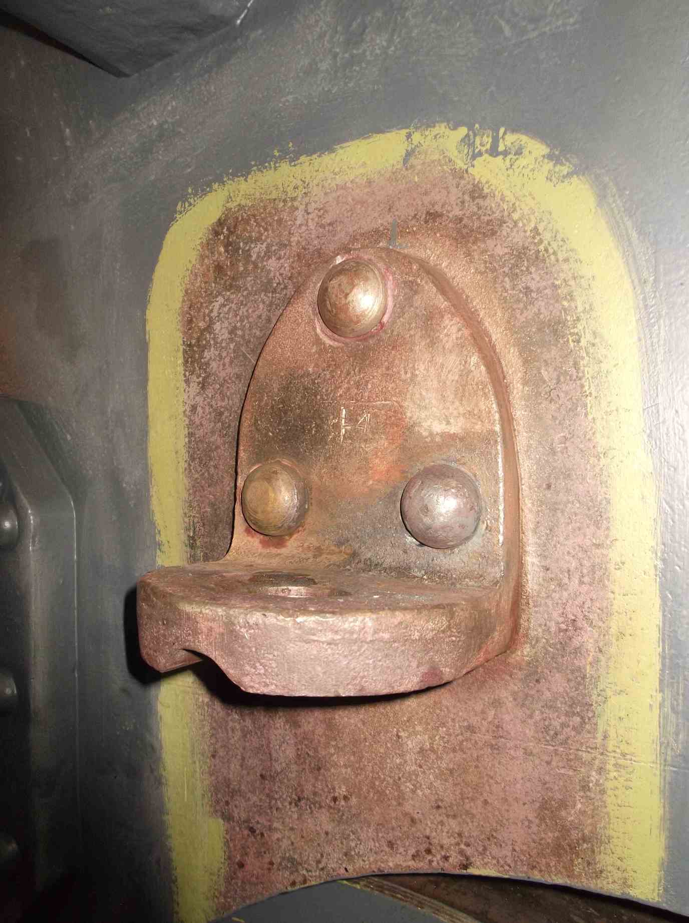
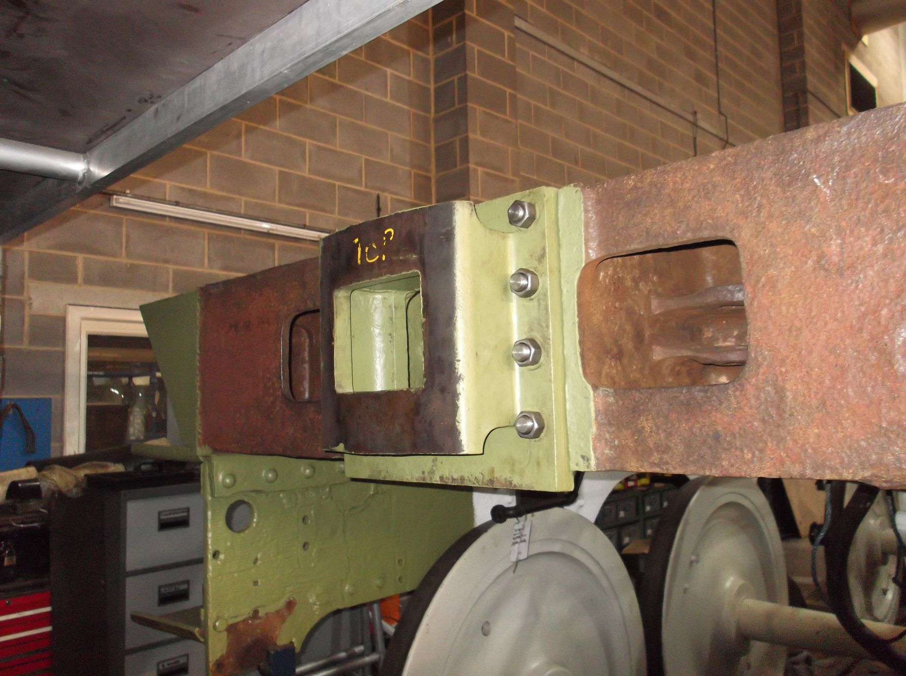
The right leading tender hornstay fitting is continuing. The built up weld has been filed back and a new hole drilled through the leading end. Further work is to be done before we are happy with the fit. A new rivet was put in one of the spring hanger brackets, held up with a snap specially machined to give us the access across the flange of the bracket. The welding at the front of the frames to restore the plate thickness is now complete and has had a grinder ran over it to take off any sharpness or edges that could catch or break the paint. This area has now received coats of primer.
The tender rubbing block that rubs against the loco trailing bufferbeam was put up. New bolting has been obtained, but the bolts need shortening. Longer bolts were bought because they were cheaper and they are easily shortened. One of the existing studs at the top of the block is short so this has been removed a new one will be made.
WEEK COMMENCING 11 February 2019
More work has been done on the tender plate work this week. More steel was collected from our suppliers and another order placed so the amount of new steel is now stacking up quicker than we can make use of it. One of the profiles for the right curved top of the tender rear was fitted this week and the top curve adjusted to match the existing beading. The plate was then drilled trough using the holes in the old plate as a template.
Around the front of the tender the new floor plate was welded to the side sheets and the front corner radii put on the plate.
The footsteps on the tender frames have worn very thin in places and this has been rebuilt with weld. It has now been ground back and painted. The front of the tender frames have been rebuilt with weld where they were wasted and this week the supporting beam was taken out. There was a danger that the welding process could introduce a lot of distortion, so we were pleased that when removed and the steps bolted up, everything appeared OK. The distance between the frames was measured near the leading tender horns and there is some measurable movement in the frames, however since last being measured the leading hornstays have been overhauled and are now a much better fit, which has had an influence on the frame dimensions. Overall we are pleased with the result. The right leading hornstay was finished this week.
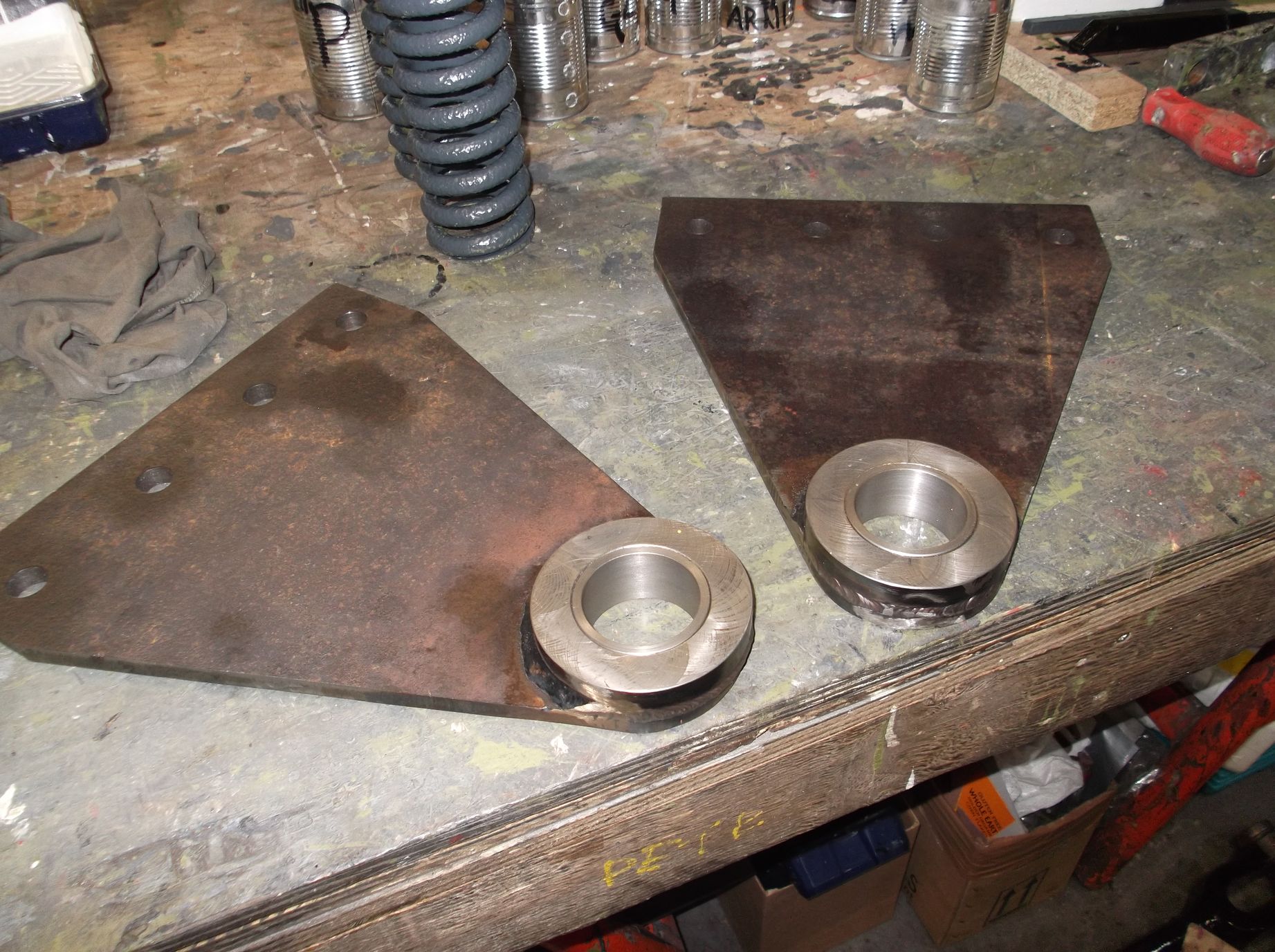
Recently we have been going through the dimensions of the tender frames for the axleboxes and bearings, which are yet to be overhauled. The dimensions for the bearings have been calculated from the dimensions taken, but we have noticed that with the hornstay refurbishment this has affected some of the frames back to back measurements, so these have been reviewed this week. The leading horns have been drawn to scale and the dimensions of the leading set recalculated. This will require checking by our CME, then we can get the leading brasses refurbished.
The trailing tender dragbox is approaching completion of painting, which will allow reassembly of the draw gear and lower vestibule components. The lower tender vestibule supports are now being machined. One has been in the lathe and the weld put on to restore the thickness machined down. The buckeye coupling was gauged this week and it fully satisfies the closed gap gauge, however when open it failed the gauge. This is very disappointing and will require some adjustment to get it right. At the leading end of the tender frames, the rubbing block was secured in place. A new stud was made at York and new bolting used.
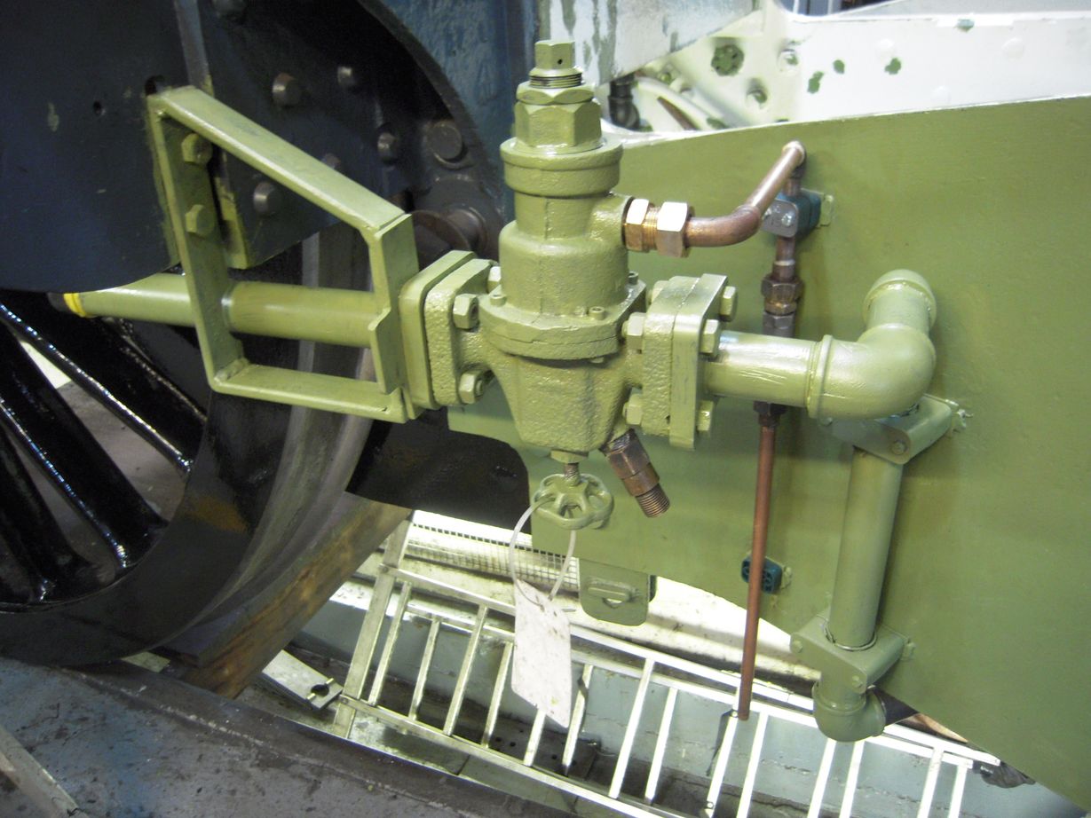
As the draincock overhaul is complete, and the operating links complete, all the valve faces on the bottom of the cylinders for the draincocks have been cleaned off this week. Meanwhile we are looking at putting together an arrangement so that the pressure relief valves can be tested.
Work continues on the tender brakegear, preparing the brake hanger holes by carefully drilling through the deformed holes removing the minimum of material. The first of the hanger bottom holes was re-bushed this week. After the bushes were pressed in they were then reamed. The refurbished recovered pin was then tried for fit and it’s a good job. Only seven more to go.
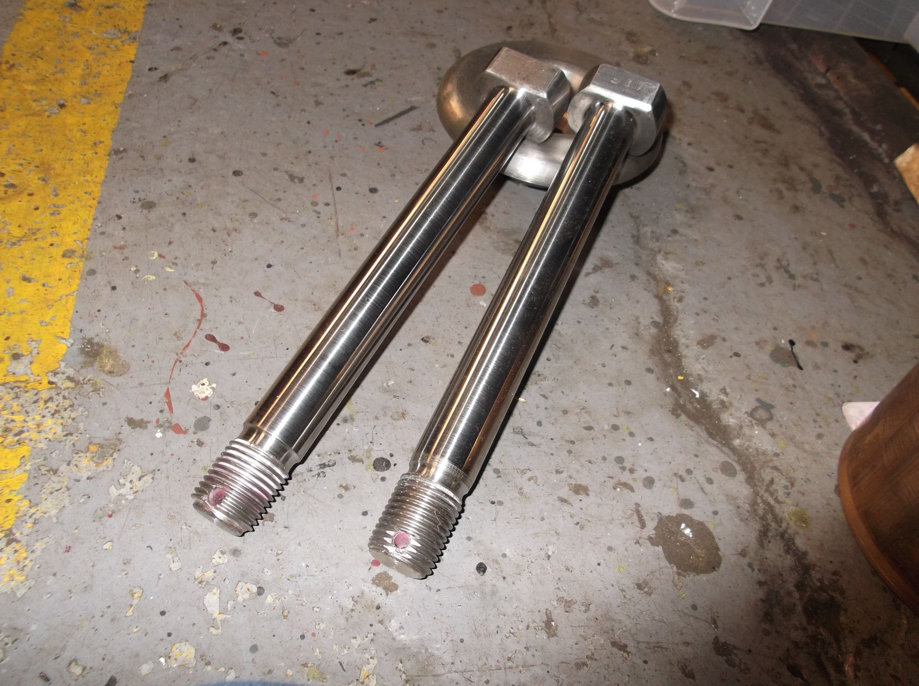
All the lower slidebars are now in position, and the positioning relative to the top slidebars is being measured. The length of the outside crank pins has been measured and the bolts for the leading crankpins polished to remove water staining and some minor marking. The drawings for the crank pin side-rod bushes are now being prepared. The fitting of the left trailing axlebox has been completed so the axleboxes for the trailing wheelset are complete. A start has been made on the left driving.
Activity on the piping of the locomotive proceeds with work progressing in a number of areas. The pipe from the vacuum clutch valve and steam sands valve both on the reverser column have been installed now that a work platform has been put in place. Two of the cast iron steam pipes that are to be renewed have been put on a pallet with the pattern for the third. It is planned to send these to the pattern makers as soon as the pallet is wrapped. New drawings for the steam pipes have been produced and these will follow the pallet.
The tender water valves are now being examined and refurbished. One valve is now lapped in and the second one begun. It looks like new spacing washers will be required for the valves and one has damage to the bottom which will require repair.
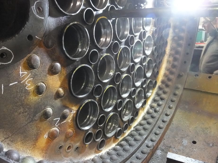
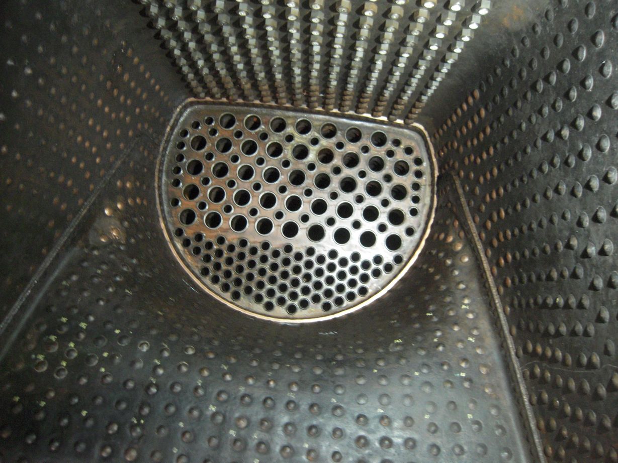
At Llangollen there’s been plenty of activity on our boiler. All the tubes and flues have been expanded in the smokebox and work continues on the crown pads. The safety valves are at York.
As previously reported, we now have new springs so the valves can be reassembled. When the springs were fitted in the valves it was found that they do not seat correctly. It had been assumed that the old springs were wasted so being a different size the spring locating rings had been modified with a spacer to take up the loss of material from the old springs. So if we took the spacers out, the new springs would just drop in. However, it looks like the locating rings were machined back to allow the spacers to be a reasonable thickness. So we will have to modify this arrangement to suit the new springs. On reflection it may be that the LNER/BR(E) springs were replaced by BR standard springs, which are made from a smaller section material and would require the additional spacers.

WEEK COMMENCING 18 February 2019
The new tender brake cylinder outside brackets had new bushes machined and then pressed in this week. They now await painting before fitting. The tender brake cylinders are now finish-painted and, though not fitted, the space they occupy in the tender frames has been simulated by a wooden mock to enable the routing of pipework in the congested space between the leading tender axle and tender front. The tender brake cylinders are protected by safety brackets. These were painted and fitted to the mock up.
The tender air system water trap was stripped and inspected this week. It was cleaned out and has now been reassembled and is being painted.
The OTMR transducer box was retrieved from store this week and given a clean. It will be put in place in the cab so that the pipework to the unit can be installed. A new enclosure will be required for the sensors.
Further work has been done to the top-right-rear of the tender. The plate has been drilled through using the old plate and the top tender beading as templates. This plate is now in its final position and tack-welded. A lot of scale has been removed from the top of the tender which had separated brackets and angles that join the various plates that form the tender upper superstructure. At the top with new plate going in, this has been removed. So the new plate had to be pulled hard to join with the existing angles. While this was being done the tender back plate at the bottom broke away being forced out by the corrosion. This released a quantity of trapped water. We will now have to remove a section of this plate across the back of the tender where the inside footsteps are, to remove corrosion and replace the plate.
The final inspection of the tender drawbar components was done this week prior to refitting. The two sets of rubber springs have now been fitted in to the trailing dragbox, as the dragbox has been painted to top coat. A lot of work has gone in to this by the painting team as it is a very complex casting.
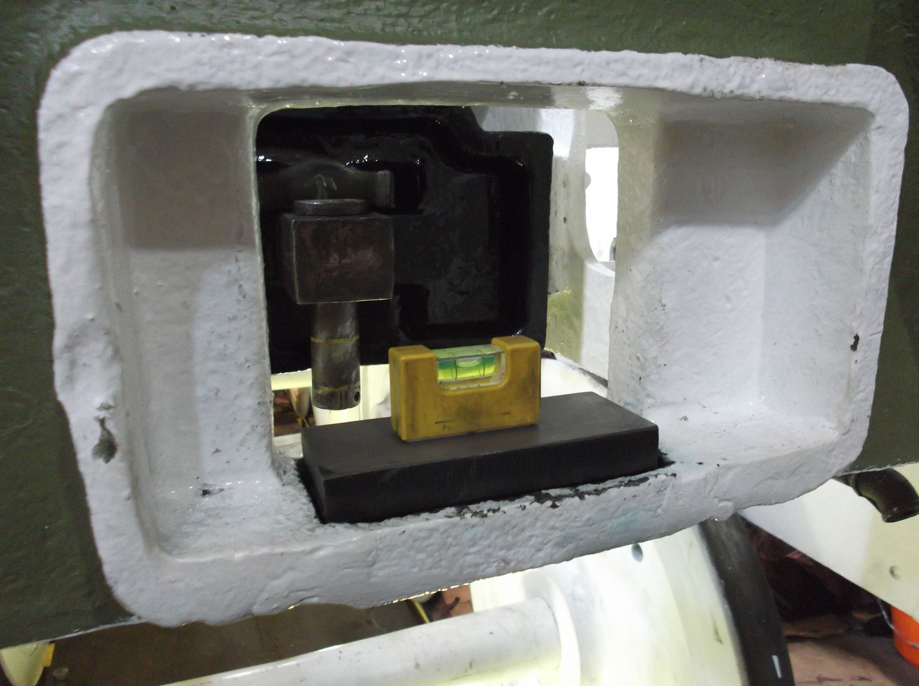
The rear drawhook has a specified height from the rail which can be measured as an offset from the rear buffers. The centre height has been marked on the end of the hook. The hook was placed on the marking-out table and the centre position calculated and marked. The height of the hook is adjusted by a block in a pocket in the trailing dragbox that the bottom of the hook slides on. The block was built up with weld and machined parallel. The pocket is more of a problem as it has worn, so a shim is being made to take up this wear and allow the block, and therefore the hook to sit level. Once everything is level the height of the hook can be measured and the block machined to give the correct height.
The second lower vestibule support rod was put in the lathe this week and machined. The machined welded sections are now machined and the ends of the welds finished with the die grinder, blending them on to the main shaft sections. The long springs that go on the shafts have been cleaned off and are now being painted.
The right leading intermediate tender hornstay fitting was completed this week, leaving only one left to do.
The trailing coupled wheelset was fitted this week. The prep work involved dressing the horn wedge edges where the adjustment of the wedges had exposed sharp edges. These were carefully taken off using a Dremel and finally polished. While we had the tools the driving horns wee also treated.
To enable us to get on to the wheeldrop, 60103 needed to be moved back. This was done under the supervision of 60103’s engineer. It was good of him to allow us to move the loco as their rods are off for winter maintenance, and moving the engine back and forward might upset the alignment of the crankpins, making the refitting of the rods more difficult.
Before moving 60007 we transferred our driving and trailing wheelsets over to the south road in the workshop. The trailing need to be here to allow them to be lifted in to the wheeldrop pit, and the driving to allow us to get the loco frames far enough forward to get the trailing wheelset in.
This required Rocket to be moved, which was done by our engineering team with the permission of the NRM workshop manager. Meanwhile other volunteers moved the axleboxes into position with other components and tools.
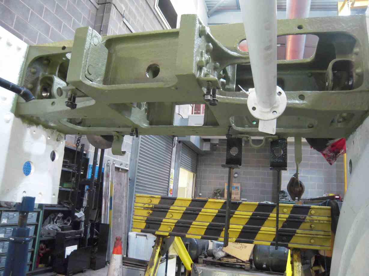
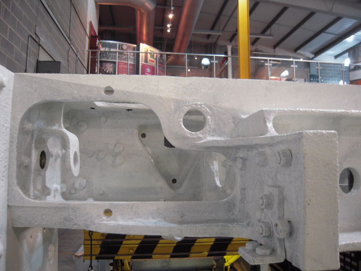
As we moved 60007 forward we stopped with the bogie on the wheeldrop. The bogie was lowered and the loco bogie sidebearers were removed. These will be machined using dimensions taken after the last fitting when the leading coupled wheelset was fitted. The bogie was then lifted back in to position.
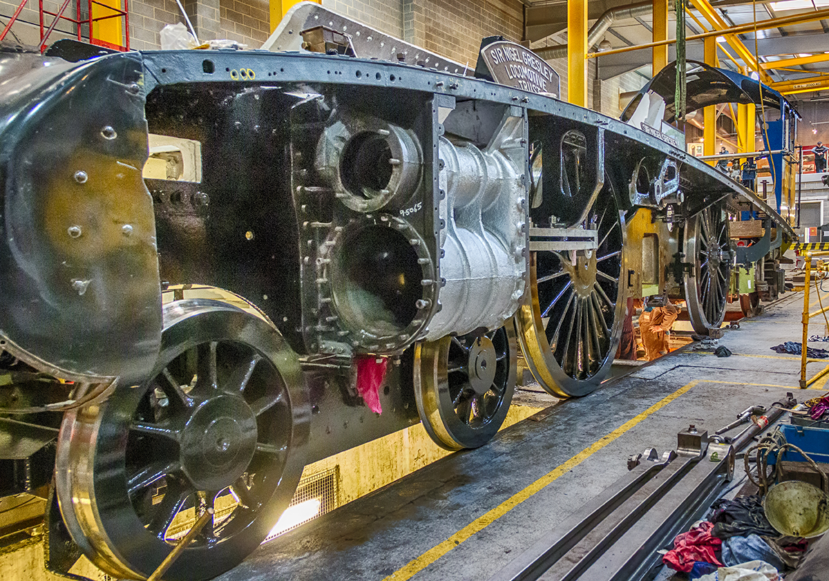
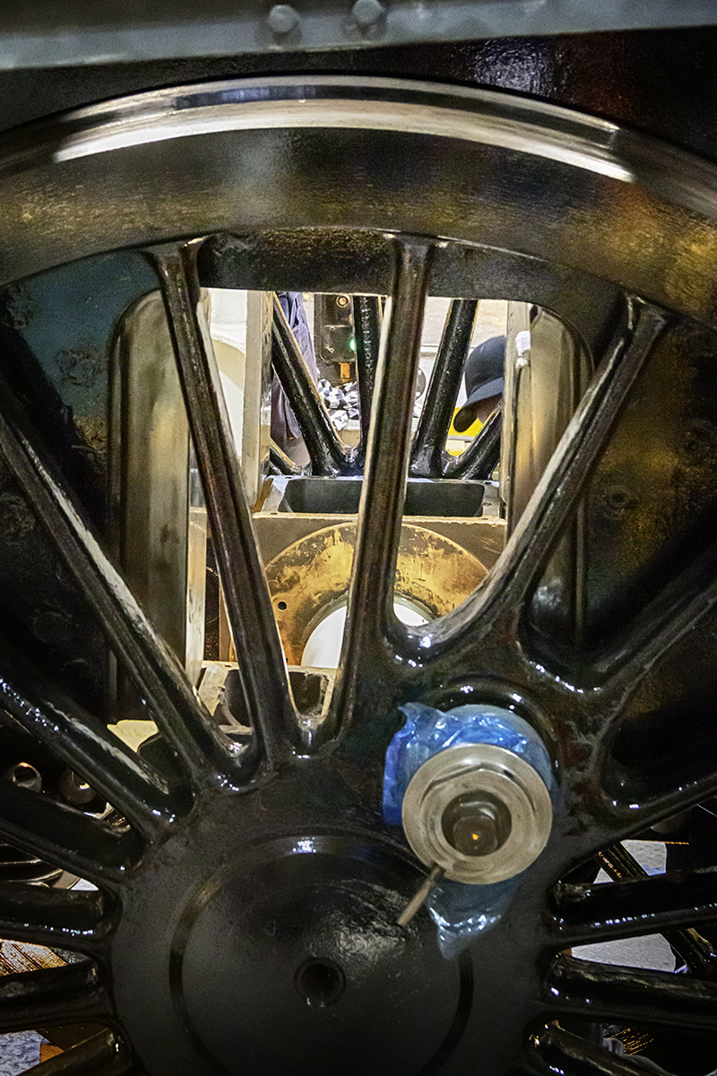
The loco was then moved forward again until the leading wheelset was on the wheeldrop for the fitting of the refurbished leading crankpin bolts. The bolts are put in from the inside of the wheel and can only be fitted when the crankpins are at the bottom of the wheel. The wheelset was lowered to nearly on top of the hornstays. Of course the crankpins weren’t in the correct position to get the bolts in so with the frames chocked the wheel was pulled round, trying hard not to scratch the paint work. With the wheel treads and rail greased they moved easily.
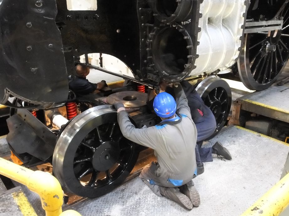
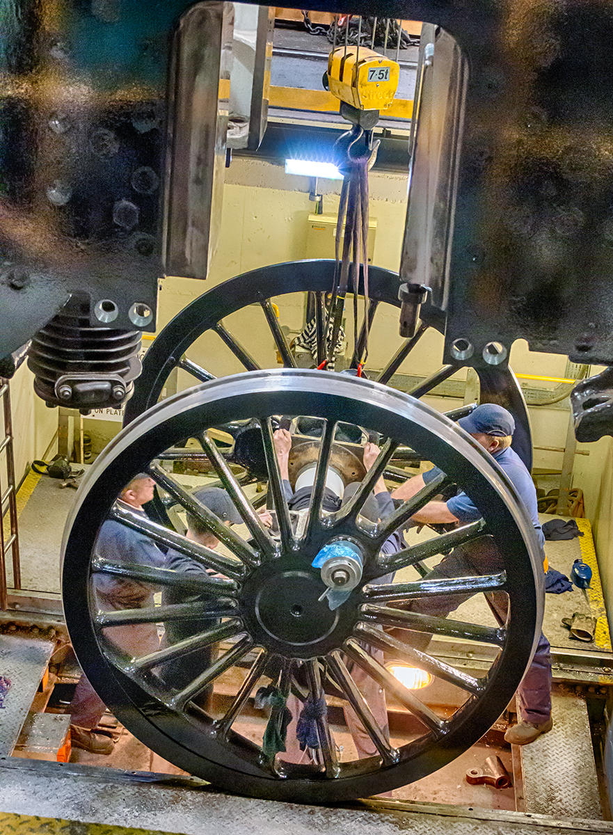
When the bolts were fitted and secured the frames were moved forward again to get the trailing wheelset horns over the wheeldrop. The hornstays were then removed and using the overhead crane these heavy components were easily lowered away. The wheeldrop platform was then lowered in to the pit and traversed from under the frames. The wheelset was then lowered in to the pit using the crane, followed by the axleboxes, placed on top of cleaned and oiled journals. The under keep brackets and hangers were also lowered on to the platform and the axlebox top plates passed down.
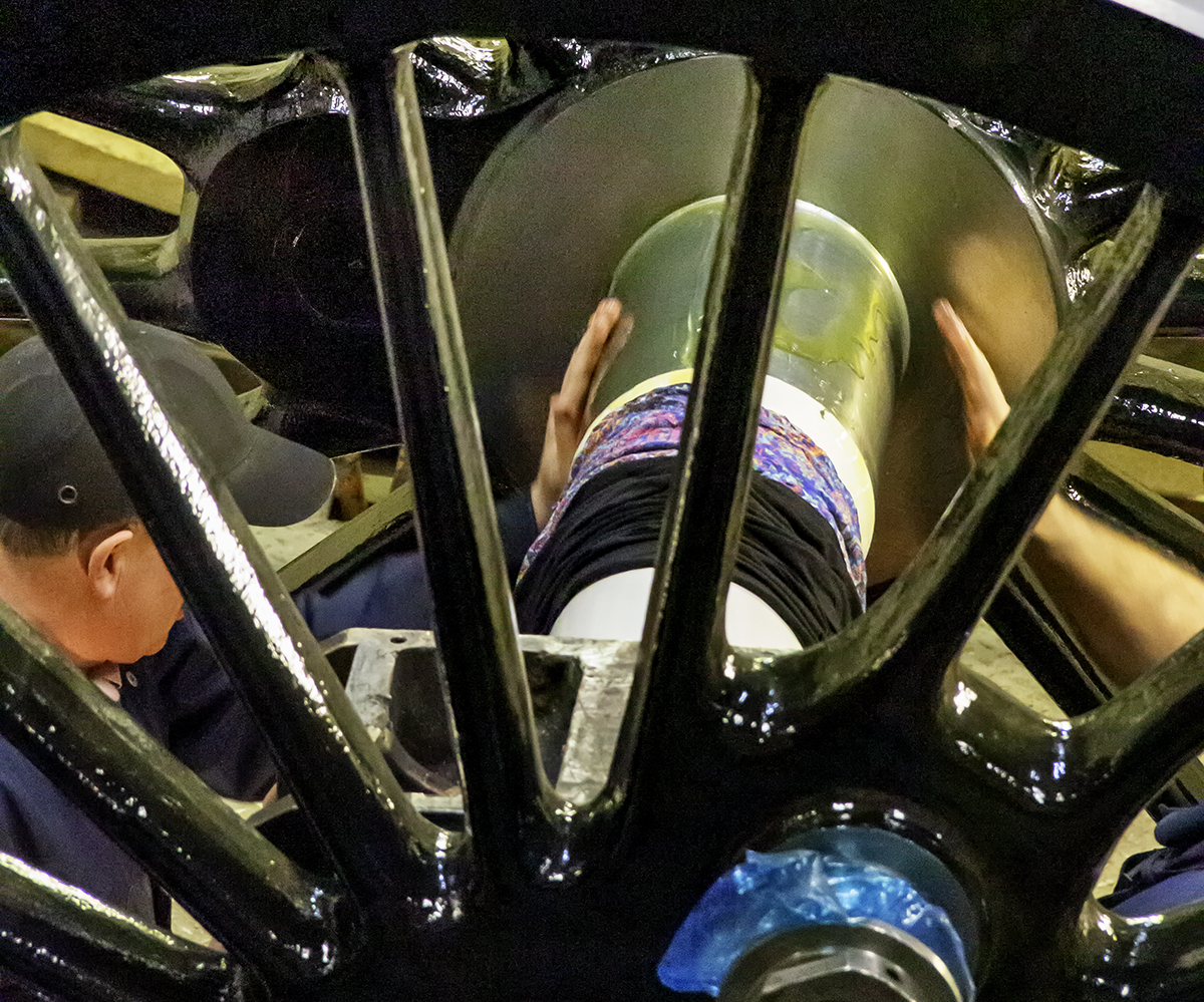
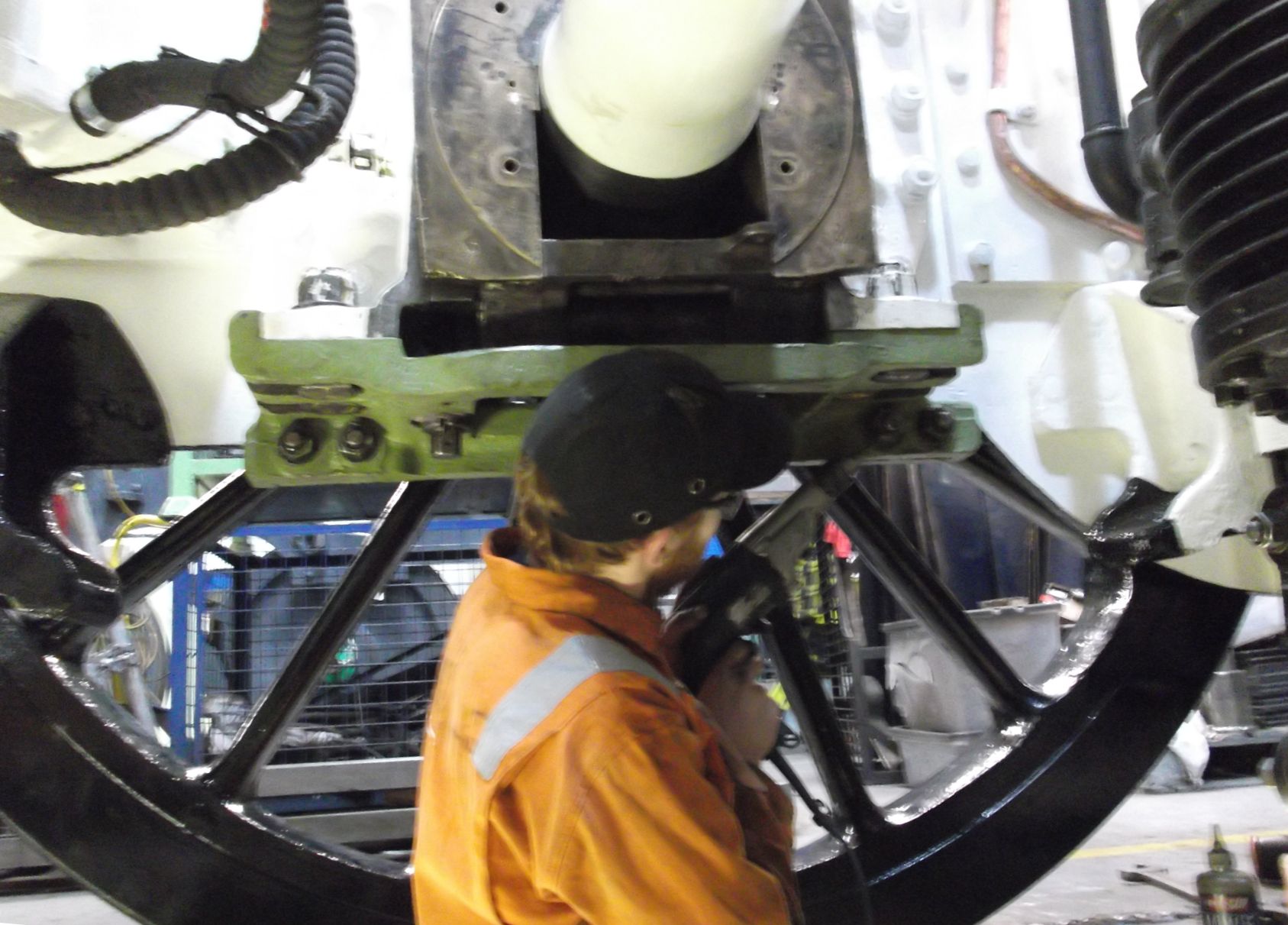
The platform was then traversed back and to a packed viewing gallery, the wheels were raised to the locomotive above. Some adjustment in position of the wheelset was required and some squaring up of the wheelset by pinching one side. As the axleboxes entered it was clear that the flange of the right side was very close to the front of the Cartazzi frame. As the tyres are new and are at their maximum size they are very close to features on the frames, as we saw when the leading set were fitted. When finally in place it can be seen that there is more clearance as there is a groove in the front of the Cartazzi frame next the to tyre flange.
When the axleboxes entered the horns the underkeep brackets and hangers were oiled and fitted. And with help from the outside of the wheels the axlebox covers were put on. The axleboxes were then fully raised and the underkeeps refitted. A really useful piece of kit, that wheeldrop.
With the hornstays fitted 60007 was pushed back off the wheeldrop and the remaining horizontal hornstays bolts fitted that were inaccessible by spokes when on the wheeldrop. The loco is now back up against the bufferstops in the workshop. The frame jacks were then put back under the frames as the coupled wheels do not yet carry the weight of the frames. The driving wheelset was put back in front of 60007 and Rocket pushed back under the wheeldrop crane.
WEEK COMMENCING 25 February 2019
In the guard’s compartment of the coach at Cranmore the floor has been taken up and the wall separating the kitchen and the corridor removed. When the new floor is in, the kitchen will be extended. The water pipes from the roof tank to
the kitchen are being re-routed.
As witnessed by an engineering team visit to Llangollen to see the boiler, the flues are being expanded in to the smokebox tubeplate, the firebox end being completed.
The cast iron steam pipes, and the pattern loaned to us were transported to the pattern makers this week. The purchase order has also been sent and the final drawings have been produced from 3D CAD models.
The tender is still taking up most of the manpower at York this week. The top tender support brackets were given a needle-gun and are now in primer. At the same time the tender vacuum cylinder side brackets were given a clean up and have been painted to primer. New bolting for the brackets are now on order.
Work continues on rebuilding the back of the tender. The flanges that form the sides of the top cover arch piece for the vestibule were fitted this week and the drilling through for the fastening bolts completed. This was done after the new section to the right of the vestibule was welded all round.
Work continues on the renewal of the bushes in the tender brake hangers. One of the hangers is worn on its ends reducing its overall width. The ends have now been built up with weld which has now been ground to smooth it off before machining.
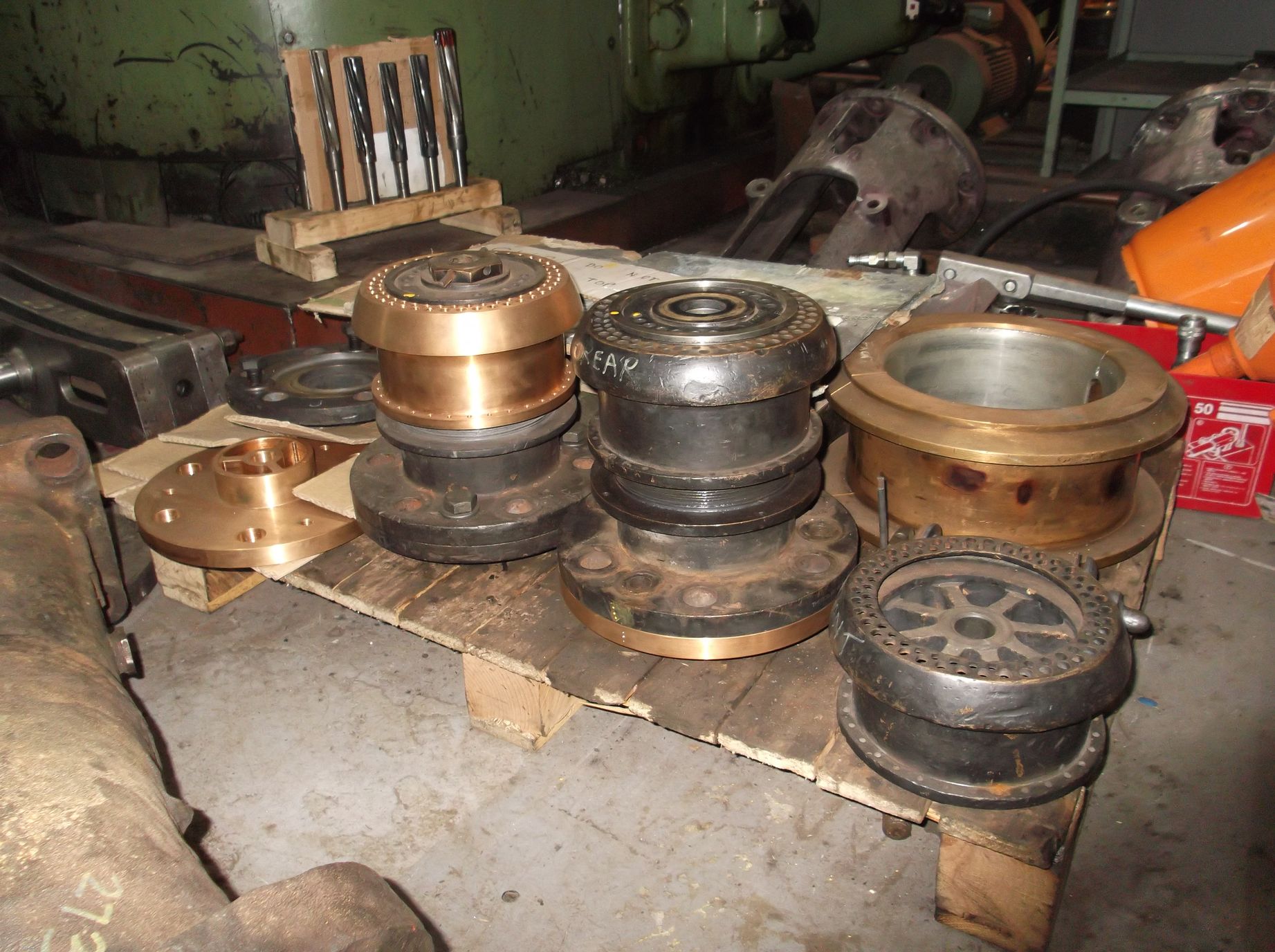
The last tender hornstay has been worked on this week and it is approaching completion. The work required on the fixing holes is now being planned. The leading set of tender bearings were taken to contractors this week with drawings showing the dimensions we require. We await a quotation for the refurbishment of the bearings. The second tender water valve has been lapped in.
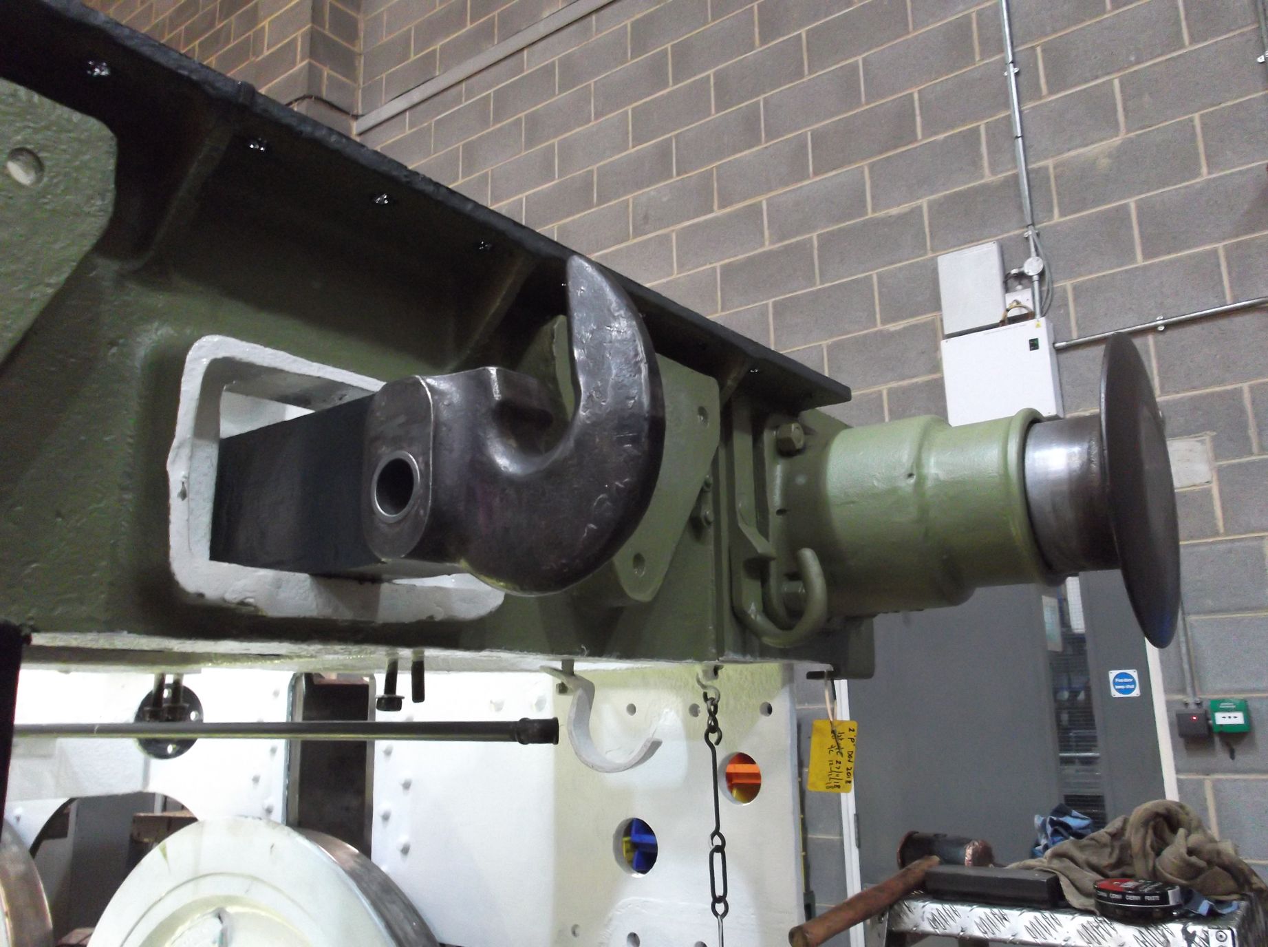
At the rear of the tender, as described last week, the draw hook rests on a block in a pocket in the dragbox. The bottom of the pocket is worn and uneven after being repaired in the past. It was decided that it would be easier to fit a shim to restore the level of the rubbing block than work in the hole, in addition there’s not a lot of material thickness to work with in the bottom of the hole. The shim was fitted this week and the hook put in position. A start has been made in measuring the height of the hook, from which the thickness of the block can be calculated.
On the loco, the slidebar gap measurements have been completed and the slidebar bolting is being examined so that a shopping list of new bolts can be made up. We have a copy of the BR drawing of the slidebar bolts to work from and compare what we currently have. It is planned to get blanks made from which we can make the various versions we require. Most will require new slotted nuts.
The middle valve, covers and valve crosshead guides have been retrieved from store and put up on the surface table ready for assessment. The left driving axlebox crown has been scraped in and the boss face started.
Two of the new horizontal hornstay bolts have been fitted to the right trailing coupled hornstay. Before this the hornstay is again flogged up as tight as possible to ensure it is fully home. As the bolts go in from the outside, the frames had to be let off the jacks and moved so that access to the bolt holes can gained through the wheel spokes.
This is the 37th update—you can read all the previous instalments here.