Weeks commencing 6, 13 and 20 January
The pipework around the atomisers is progressing with the steam supply pipes being trial-fitted, but we will need the front end casing to be fitted so that the pipe above the name plate can be fitted. Some of the ends are poor and will have to be remade.
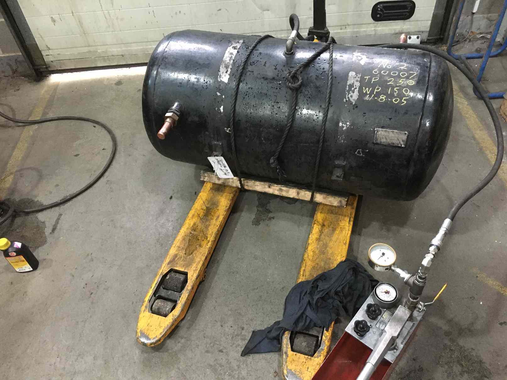
The tender top air receivers are being prepared for hydraulic testing. The space in the tender where the tanks will be fitted is being painted ready for them to be refitted.
The expansion link trunnion bearings and housings have been fitted, followed by the expansion link sides The radius rods and expansion link centres and die blocks have also now been fitted. The conjugated gear, equal lever and 2:1 levers, and the links between the leading valve crossheads and the levers have now been bushed with a mixture of bronze and steel bushes. The bushes have been reamed to fit the new hardened pins.
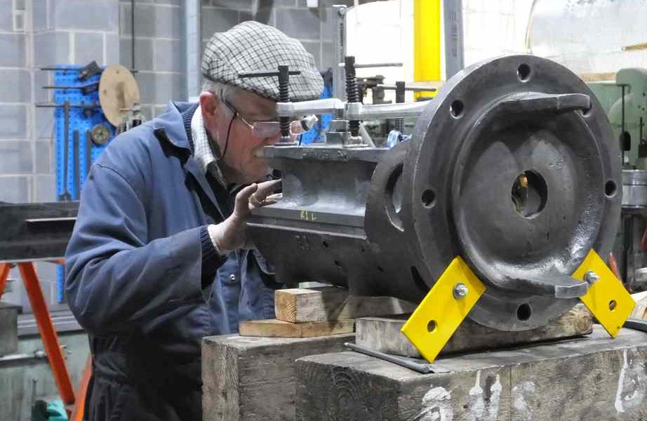
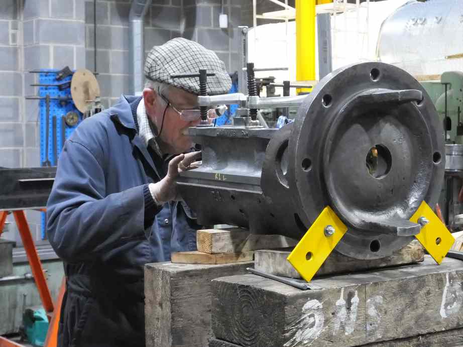
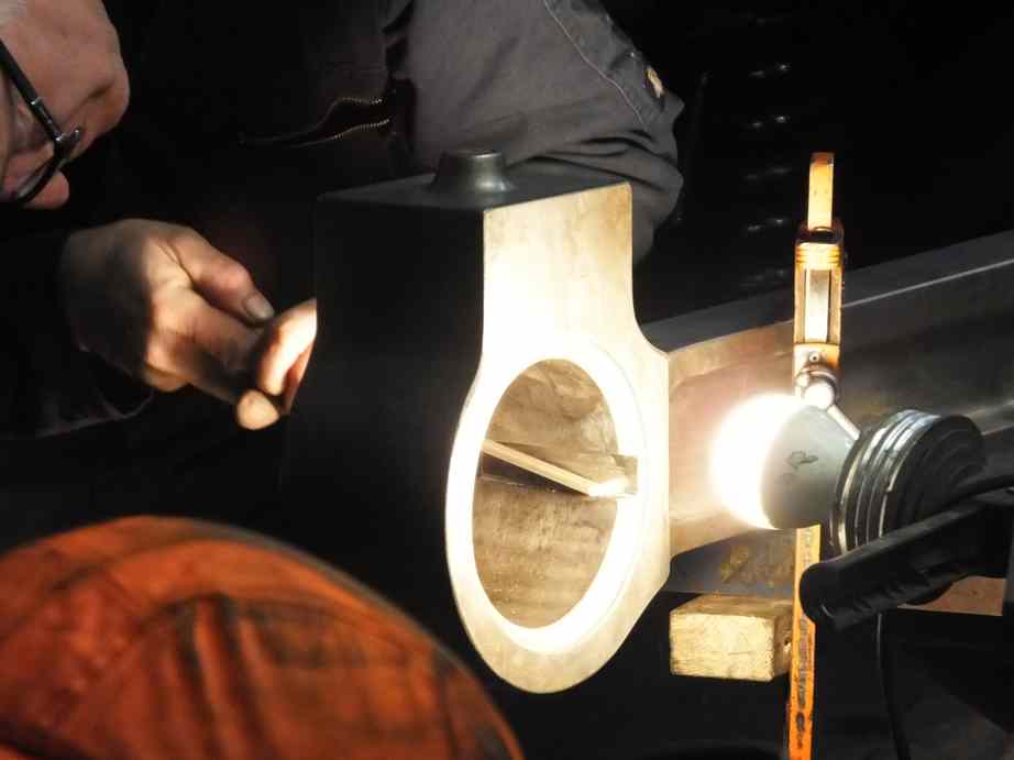
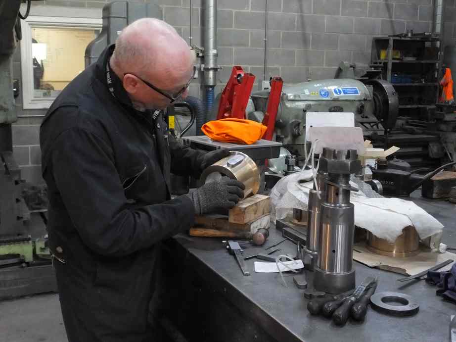
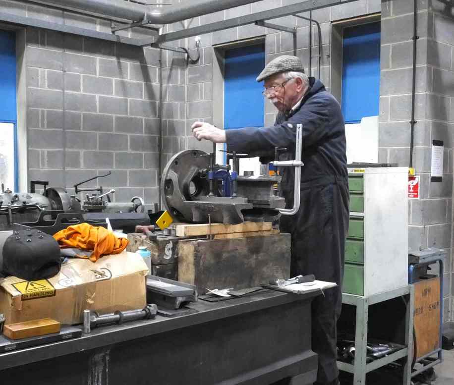
The fitting of the new valve guide is being progressed. The valve cover was put up on the marking out table and as the guide has to be accurately set up parallel to the valve cover centre and at a specified distance to accommodate the valve crosshead. Drilling bushes have been made so that pilot holes for the bolt holes can be accurately positioned in the guide for the eventual reaming through for new fitted bolts.
The keys for the coupling rod bushes and the outside big end bushes are being fitted. Some of the keys have been machined to suit their locations due to the wear in the rods. The keyways in the rods show wear so time has been spent dressing the keyways.
New felt oiler pads for the bushes are also being made, following the BR instructions.
The Smiths speedometer has been refurbished and is now being painted. The calibration results for the OTMR pressure sensors were tabulated and the results examined. An anomaly was noticed and when investigated an error in the calibration was found, so the sensors were returned to the calibration lab. They have been re-calibrated and new certificates produced.
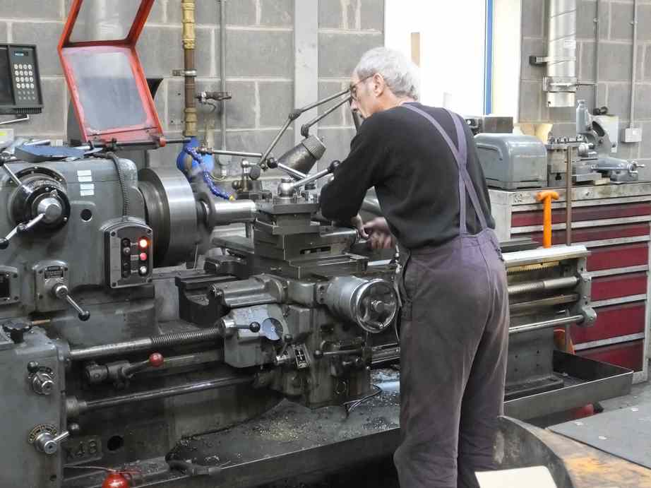
The blanks for the knuckle pins that join the coupling rods together are now at York. No time was wasted in starting their machining and fitting with the left pin well on the way. It is a good machined fit in its rod and is now being blued on to the tapers in the rod.
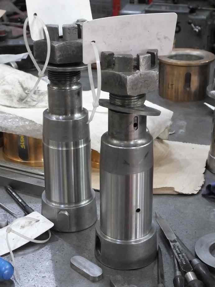
The gudgeon pins have now been ground on their journal surfaces to return them to round and true. The finished diameters are now known so the little end bushes can be machined. The bushes have been preliminary machined. Before the pins could go for grinding the middle pin had to have a centre made to fill the oiling hole in its end. This was done and the centres in the other pins were cleaned out. All were mounted between centres and ovality and eccentricity measured so that the amount of grinding required would be known. Fortunately none of the grinding would take any of the pins below scrapping size.

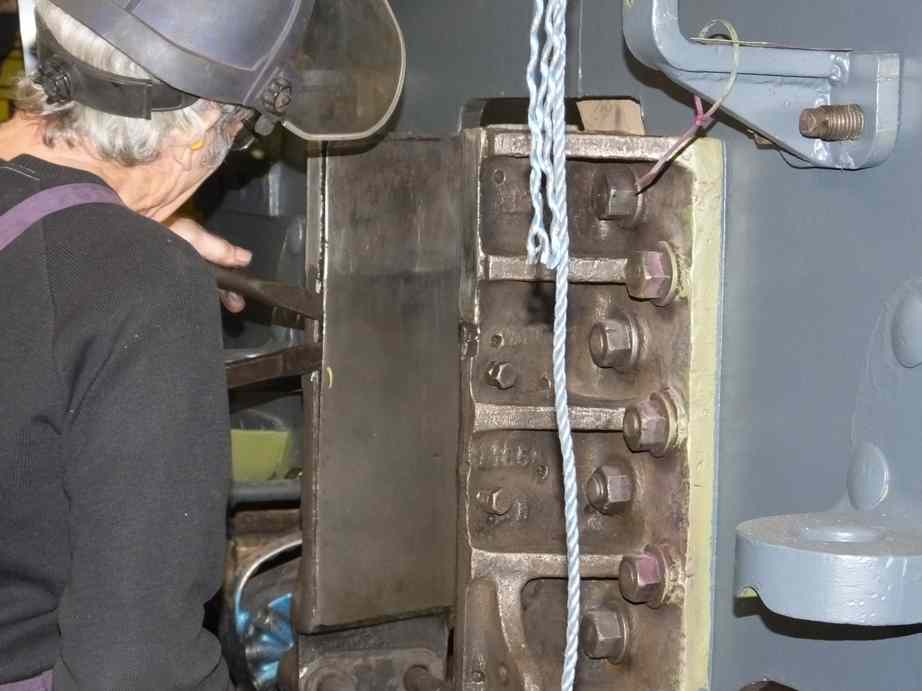
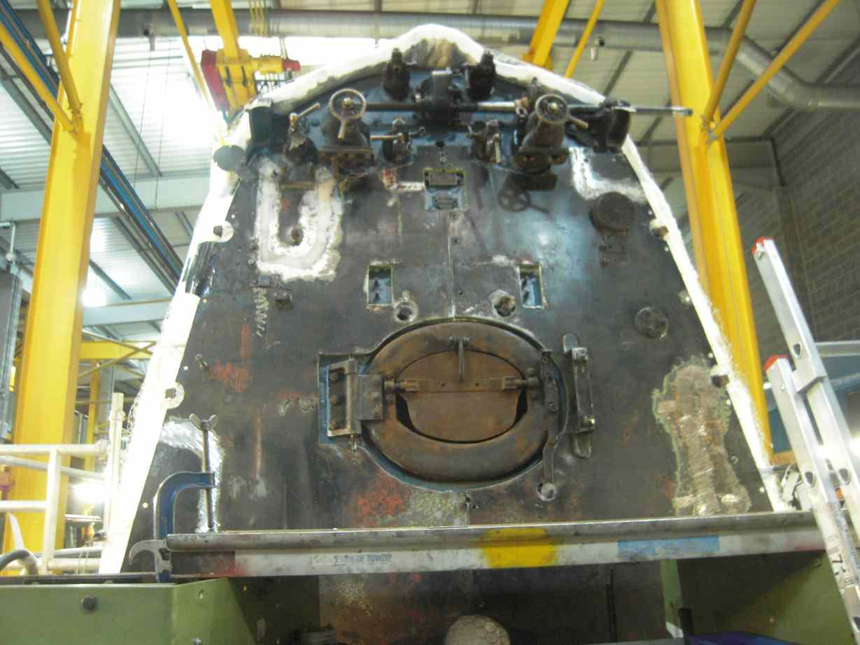
The backhead cladding has been tried up on the new and reconditioned studs fitted in to the boiler. A number of backhead components had to be removed to allow fitting. While doing this it was noticed that the regulator cross shaft was not sitting correctly on the fireman’s side bracket. The bracket has now been moved to contact the bottom of the shaft. To do this the stuffing box cover had to be removed to allow the shaft to be move sideways to uncover the bracket securing nuts. The bracket is now correctly positioned but the stuffing box seal will have to be remade.
The backhead cladding has had various sections cut out in the past. These sections are now being welded back in place. Some patches of new material have also been inserted and a very smart job has been done.
With the backhead cladding tried on and with a method of getting it to fit without requiring access to the cab floor, the pipework under the floor can be refitted. This is now well under way.
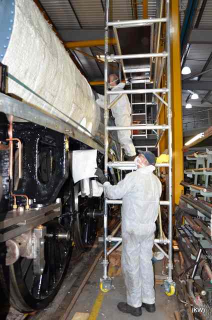
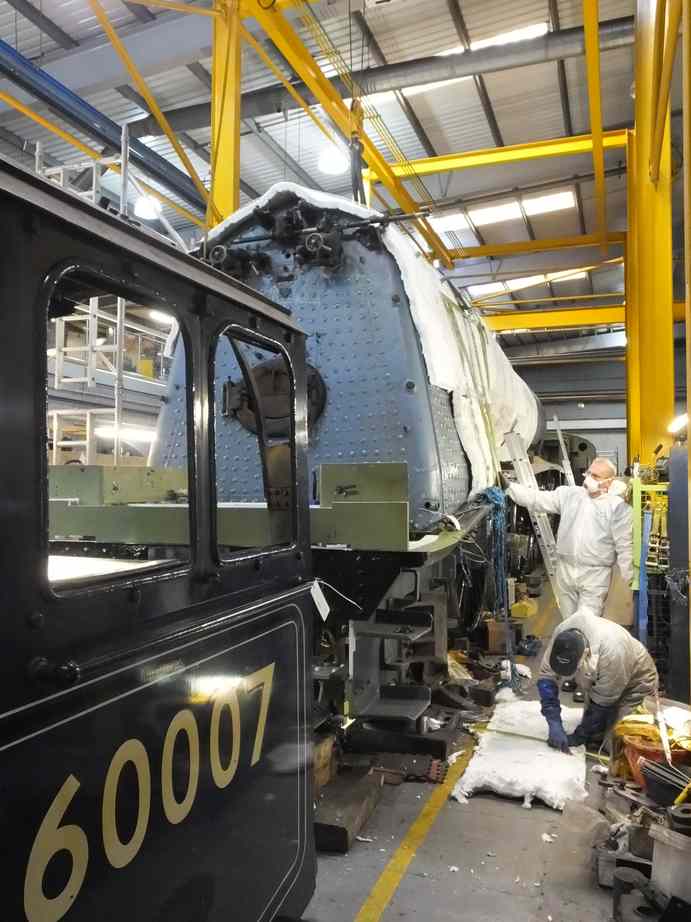
The boiler insulation has been delivered to York and has been fitted to most of the boiler barrel, using our new scaffold towers.
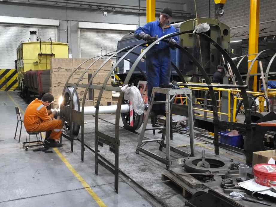
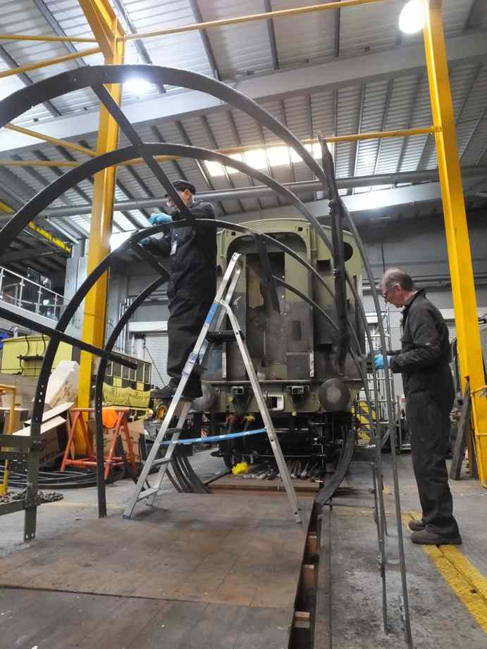
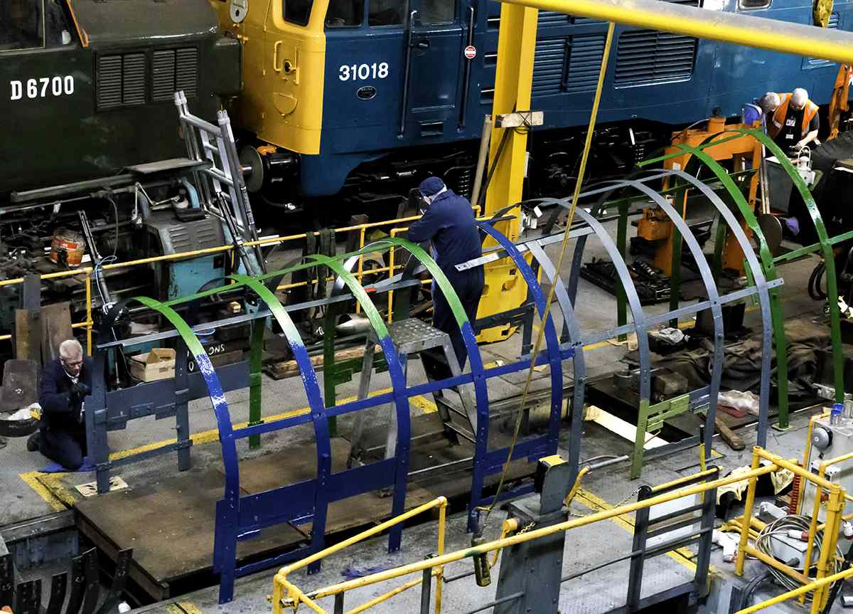
With the insulation going on, the crinolines have been moved clear so that they can be worked on. The firebox crinoline was tried on so that a couple of brackets on the footplate could be re-positioned. To gain a bit more clearance between these brackets and the boiler, bushes were made and welded on the back of the brackets and tapped through for the securing screws. The brackets have now been welded in place. The firebox crinoline has now been painted in primer after it was weld repaired. The other 2 crinoline sections have been cleaned down and wire brushed by the 007 Gang of junior engineering trainees, ready for repair and painting.
The damper linkage set up is being finalised. Due to the extra components such as the air pump and air pipes the positioning of the damper linkage has to be different from the original arrangement.
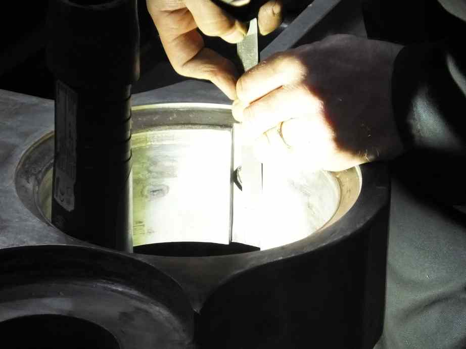
The cylinder relief valves are now being tested for their blow off pressure against our calibrated pressure gauge. They require adjustment which is achieved by the machining of a spacer which adjusts the compression on the internal spring. Three of the six valves have been tested successfully and witnessed.
The overhaul of the Cartazzi continues. A lot of time has been spent on cleaning the axleboxes and other components. The rubber springs on the ends of the spring hangers are life expired and new ones will be made. The rubber and stainless steel plates are now at York for assembly, with the steel being blasted.
The bronze Cartazzi wedges, or inclined planes, have been machined by one of our volunteer Engineering Team to restore the correct profiles.
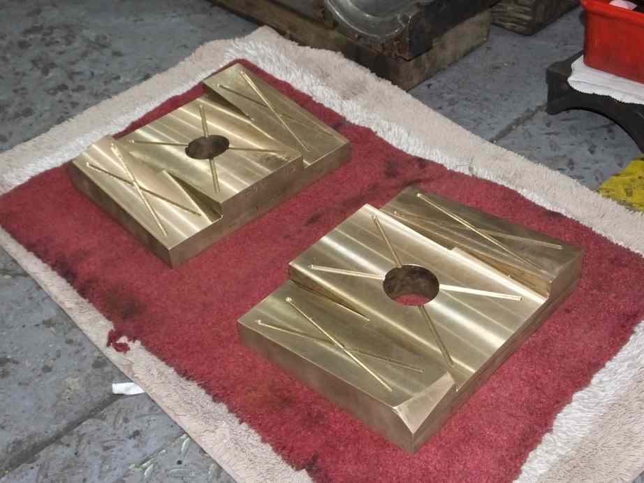
The trailing Cartazzi horn liners were very worn with the right side worn through. They have now been removed. They were originally manganese steel which is expensive and difficult to work, so a cost effective solution to the re-lining of the horns is being investigated.
The Cartazzi wheelset was tested before Christmas and was found to be free from defects so it was cleaned down and has now been painted to gloss top coat. The journal ends have been carefully dressed to restore their end radii.
One of the Cartazzi brasses was found to be cracked and will require replacement. Quotes for a new casting have now been received and an order will be placed.
One of the Cartazzi hornsays was found to be cracked. This is currently being weld repaired off site.
New spindle sealing copper washers have been fitted to the bufferbeam steam heat valves. These will now be pressure tested.
The loco brake gear pins and bushes are being worked through. A number of bushes have now been renewed, with more to do, and material is now at York for the manufacture of new pins.
Over the Christmas break the tender coal gate hinges were machined and the full assembly put back on the tender. The hinges are bolted in place but were previously welded, probably due to the poor condition of the threads in the hinges, so they have been welded in place again. With the coal gate now level the hook catch is too low. The catch had been drilled to drop the hook, so the hook was put back in to its original hole and everything is spot on. The catch is has also been re-welded in place.
The tender corridor end has now been welded on to the tender front plate. A new section of steel has been put in to bridge the transition from the original front plate top flange and the new section. Before the last section of corridor roof is welded, bridge pieces have been welded across the corridor roof. This will help to prevent the tender side being pulled in by the contracting weld material.
Weeks commencing 27 January, 3 February and 10 February
The tender lower vestibule support brackets have had the top sections welded back in very accurately by K D Flavells. They have been tried on the tender bufferbeam and fit fine so are now being painted before final fitting.
Insulating the boiler has continued with the firebox and backhead now covered.
The crinolines have been cleaned down and were moved and placed in order in front of the loco. They have now been painted by the painting team. Some repair work has been necessary with cracks and loose joints welded up. They have been painted to blue top coat gloss to use up old stock not now suitable for painting the outside of the locomotive. All three sections of crinoline were then lifted and fitted to the loco.
While the crinolines were being fitted the painting team moved on to the belly straps that are fastened on to the crinolines and pass under the bottom of the boiler. As soon as they had a day or so to dry these were also put in. The belly cladding is now being worked on with most of it reusable. The straps that secure the belly cladding are being prepared for fitting and the securing studs have been cleaned and checked.
With the insulation and crinolines in place the first large sections of backhead cladding were fitted. The cladding is being prepared for paining in-situ.
At the front of the tender, work has been done on the cab floor upstands with the original material being cleaned up. It is planned to reuse some of it.
There’s a water tap on the front of the tank which fills a bucket located in a hole in the floor. Under the bucket is a drain pipe. The pipe is fastened to the tender floor with a flange. The new floor plate has now been drilled to take the flange and a new securing bracket made for the lower end of the pipe. The pipe needed some repair work and is now at painting.
New steel for the battery box and the tender streamlining has been specified and an order placed for its supply.
New bolting has been received for the tender balance weight that makes up some of the tender cab floor structure.
The low-level tender filler pipe with a shut off valve has been refitted. This required the internal pipe that runs through the tender water space to be resealed against the inside of the tank and the large external isolation valve refitted.
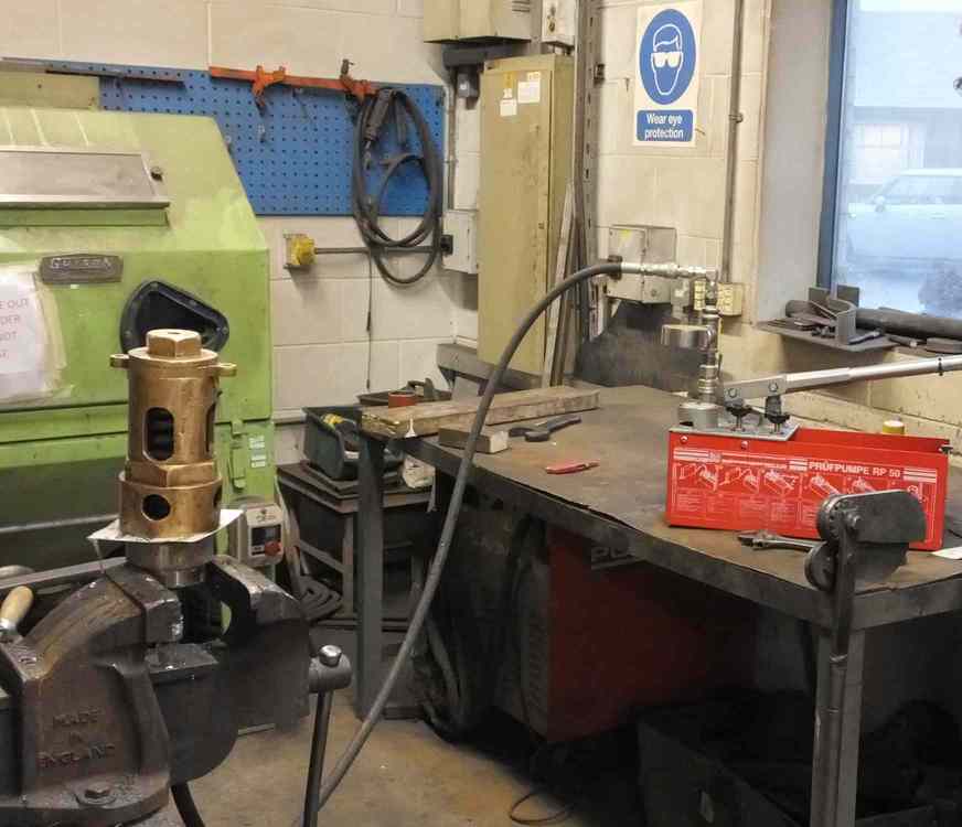
The pipe fitting team has hydraulically tested the 3 tender top air tanks. All passed successfully. Our insurer has now also examined the tanks and has passed them OK for further use. They have now been painted and are ready to be refitted to the tender. The smaller of the air tanks was sat on wood which disintegrated when removed, so new steel brackets have been fabricated. These copy the way that the larger tanks are retained.
The installation of the tanks has been reviewed as the pipe runs have to change as they have been rerouted through the tender. The pipe fitting team are examining the best layout so using as much of the reusable old copper pipe as possible and accommodating the new pipe runs.
Meanwhile, the injector pipework has been cleaned and annealed. The air ministry joint components are also being examined for reuse.
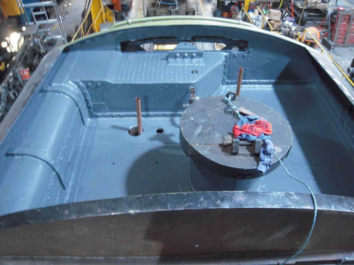
The painting of the tender top around the water filler where the air tanks are located has been completed.
The middle cylinder trailing atomiser oil feed fitting has been fitted with a new specially made copper washer.
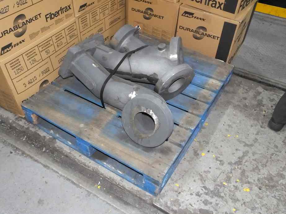
The cast-iron steam pipes are now with contractors for machining.
The fitting of the keys to the rods and bushes for the coupling rods and outside big ends is now completed. All the oiler felt pads are also now made.
Work continues on the knuckle pins. Both have been made to give best fit in their rods. One has now been lapped in and work on the second is well advanced. This has required a lot of work taking out deformation from the holes in the rods.
Work continues on fitting the new valve guide. It has been drilled through and one of the holes has been reamed and a fitted bolt roughed out to locate the valve guide for reaming the second hole.
The other valve guides and valve chest covers are being trial assembled and examined.
The valve spindles were put up on the marking out table and checked for straightness. All check out straight.
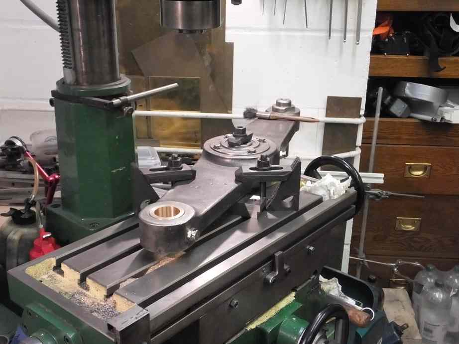
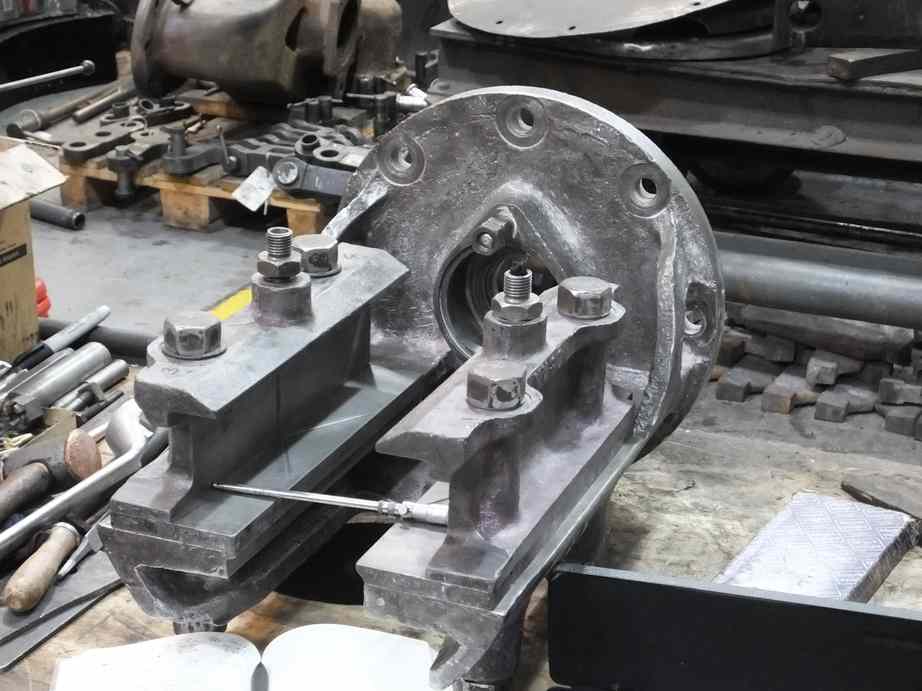
Two of the valve cross heads have had their old whitemetal melted off to allow machining after they were built up with weld. To machine them accurately the bore for the valve rod is used as a datum. This has required a jig to be made.
The OTMR sensors have now been collected from their second visit to the calibration lab. This time the calibrations make sense. The results have been sent to the VAB and the previous service sensors are suitable for future use.
The new Cartazzi brass is on order with the pattern sent to the foundry.
The machined Cartazzi bronze wedges have been tried on their mating steel faces. Unfortunately the fit is not good. One of the steel sections has now been put up on the marking out table and is being examined closely and our options considered.
The cylinder relief valves have now all been successfully hydraulically pressure tested.
The saga of the buffer mounted steam heat valves drags on. They have been lapped in and were again pressure-tested. One leaked quite badly so was taken apart to find that the back venting valve had not located correctly when reassembled after overhaul and had damaged the valve. The old valve has now been replaced by a new part. The spindle also shows damage but this may be recoverable.
Work continues on the loco brake gear with the replacement of the steel brake bushes.
This is the 47th update—you can read all the previous instalments here.
I am so glad to see that Sir Nigel Gresley overhaul is coming along nicely, I have a good feeling y’all gone do a good job on her, just like y’all did the rest of trains. , and not mention I’m a huge fan of Sir Nigel Gresley locomotives. His A4 Pacifica is one of my favorite class