Week commencing 7 May 2018
The removed coupled axlebox thrust inserts have now been measured and quotes for material obtained. Our repair method has been documented, including the specification of the material for the inserts, and when approved material will be obtained.
The painting team has now applied varnish to the coupled wheels and they’ve been prepped for their second coat. The outstanding bogie springs have been returned from the suppliers, with our new spare, and these are being painted prior to the assembly of the bogie.
The front coupling assembly that the loco carries in traffic varies from the original LNER/BR arrangement, as carried by 4468 and 60009. As we need to renew the front hook spring, we are in the process of manufacturing new springs to the original arrangement. To adapt this layout to our loco, an additional plate is required between the spring and the rear of the buffer beam. The plate is profiled to clear some rivet heads in the bufferbeam. To prevent it from moving and wearing the hook shaft, the plate is now held on pins in the bufferbeam. The plate is presently being bored to increase its clearance on the hook.
The rubber for the front hook springs is on order and the plates between the rubbers require blasting and deburring.
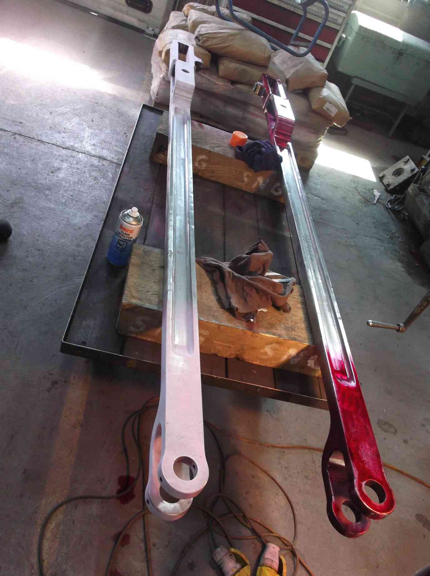
The last of the lower slidebars has now been dye penetrant inspected and no defects were found.
The outside of the smokebox door has been needle-gunned and painted. We’ve also worked on the door bar and dart, with the bar descaled and the dart cleaned for inspection. The dart threads are in good condition and have been dye-penned. No defects have been found and after a bit of tidying up will be fit for further use.
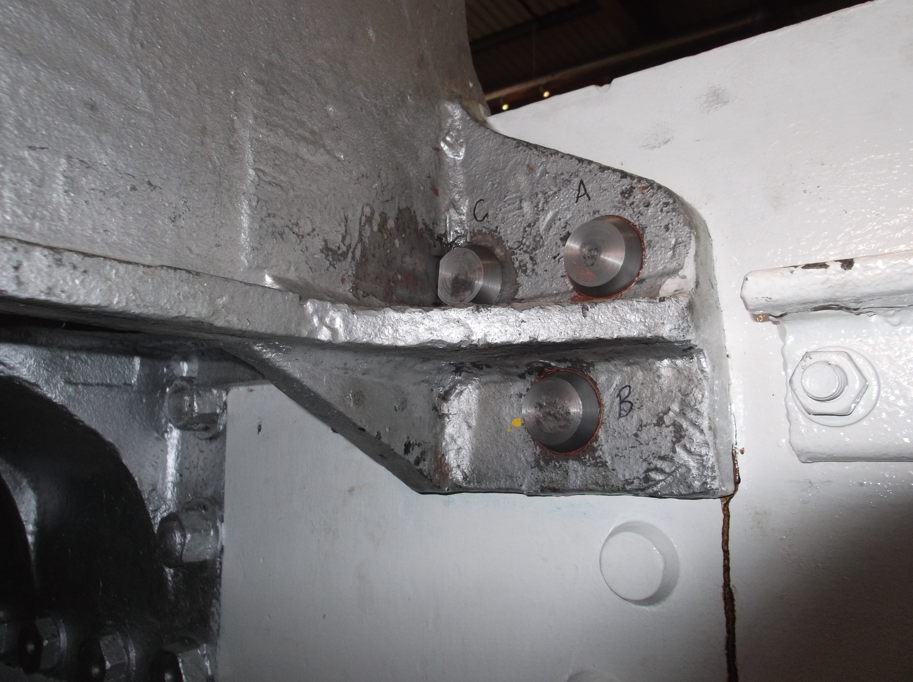
The last of the leading and upper cylinder and saddle fitted bolt holes have been spotfaced and bolts fitted. This has been an awkward and lengthy process, requiring tooling to be made to fit specific holes and locations. The bolts are also made to fit their specific holes, for diameter and length. In a couple of locations the seats for the bolt heads have had to be cut by hand with hammer and chisel. In other locations special washers have been required. However, the cylinders are now as well secured as they have ever been.
The loco bogie side bearer holes that are in the bottom cylinder flange have now all been reamed. The side bearers have been tried up and will need careful fitting—a method for the best way of doing this is still being worked on. As they are a relatively simple fabrication it may be easier to start with new material.
The final couple of horizontal hornstay bolt holes have been reamed. The holes now require countersinking, to ensure the countersinks remain on the hole centres. The countersink has been specially ground and has been received from our supplier.
Work continues on the safety valves, with quotes for material and machining from solid and patterns, so that we can decide the best way forward. Simultaneously, we have been talking to other loco owners about the possibility of purchasing additional parts on their behalf and so reducing unit costs to us. At the same time work continues on trying to determine original manufacturing dimensions and tolerances, as we only have access to worn valves.
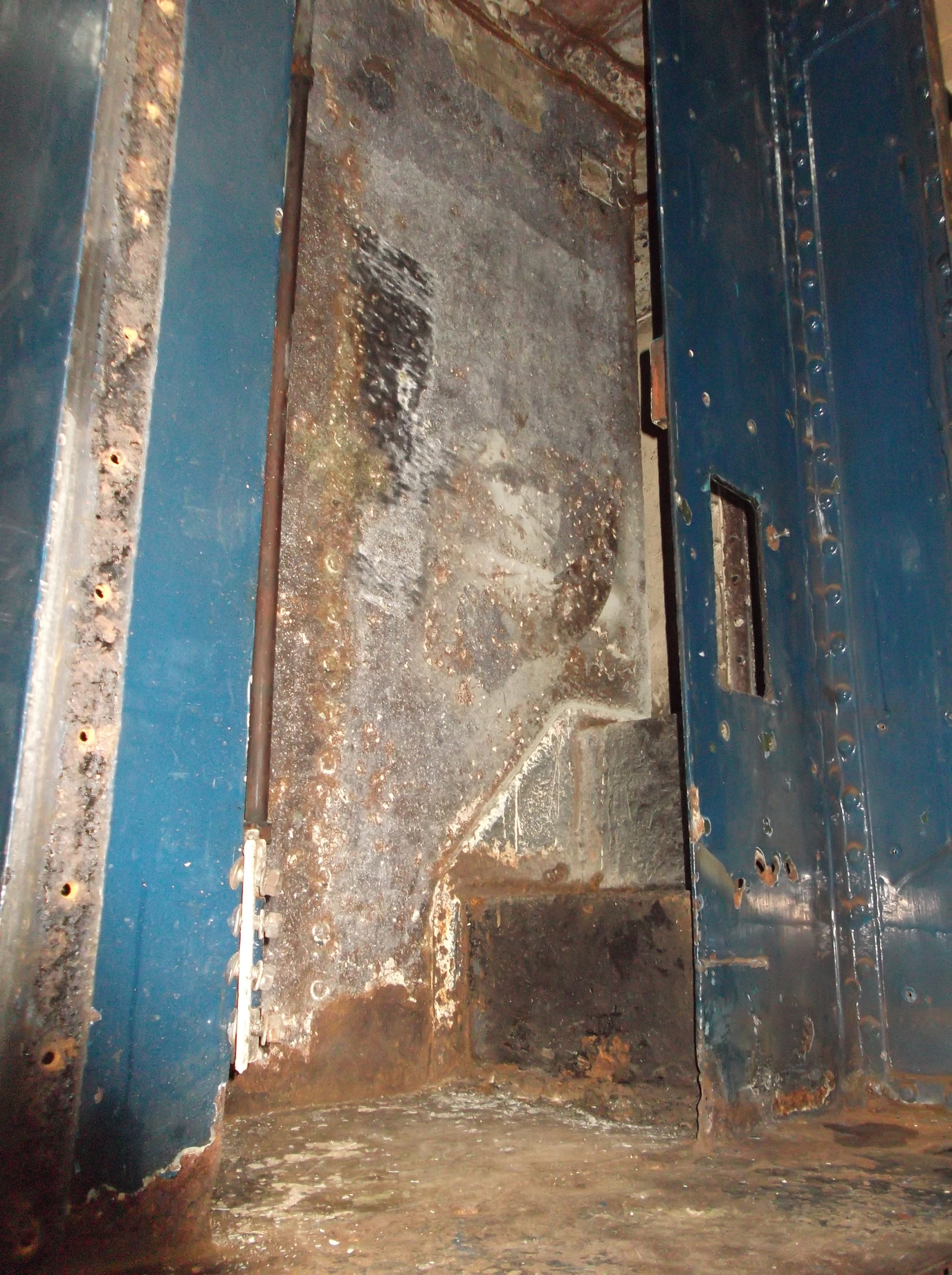
We have now had visits from two lifting contractors with a view to obtaining quotes for the lifting of the tender tank clear of the frames. Both have described the same method of lift, which is the same as we had devised. Meanwhile, work continues on the tank with all of the corridor roof removed, and new steel work has been ordered. More stiffeners have been added across the corridor to the outside of the tank now that it is not supported by the roof. Descaling around the outside of the water tank, along the corridor and vestibule has uncovered some holing due to corrosion, though this seems to originate from outside of the tank. Most of the way up the corridor the tank appears to be in good condition.
On the front of the tender, the GSMR user interface unit and the AWS battery box have been removed, as there is work to be done on the tender front platework.
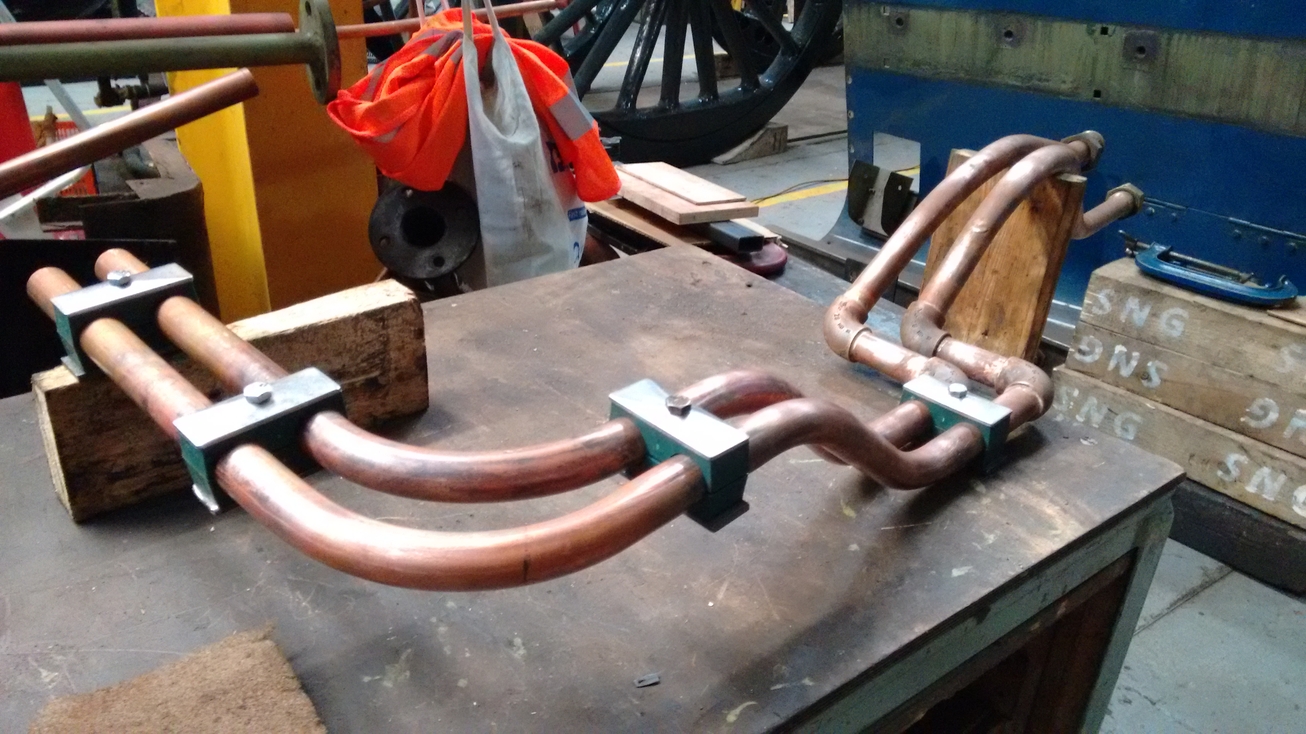
The pipework fitting continues, with new pipe installation giving the assembly a very professional appearance. A number of joints are being relocated to enable easier access when in traffic. The air pump governor and its pipework have been refitted temporarily as the governor is to be relocated. This gives us an idea of the space required for the governor pipe runs.
The ashpan is very near completion. The ashpan damper door screen requires new hinges and these are now being made.
The temporary screws holding the middle cylinder cladding have been replaced with permanent fasteners. Now that’s sorted, the ends of the drain cock cables to the linkage that runs under the cladding have been finally fitted. The cab handle has been operated and the linkage works well.
The drain cock operating rods are supported in cast slots in the side of the drain cock valves. As they are steel, the links wear the slots. It is apparent that they have been repaired before by rebuilding with bronze weld, so we decided to do the same again. This has now been done and a really good job has been achieved. During this repair it was discovered that one of the valves had a pin hole, which would allow cylinder steam to escape. Upon inspection of the other valves, we found that some show a surface defect in this same location, so it appears to be a common casting defect. Two valves were found to require the repair of a pin hole, and both have now been repaired.

After a reorganisation of the workshop the large vacuum cylinder was moved to the rear of the loco and was getting in the way, so we decided it would cause less obstruction in the loco frames. This has now been fitted. Before fitting, the stirrups that accept the cylinder trunnions were cleaned out and edge wear carefully removed. The stirrups were greased and the cylinder fitted. To stop it flapping around the cylinder has been tied up. The flexible hoses to the cylinder we tried on, since there was concern about their fit as they have a larger outside diameter than the ones removed from the loco (the smaller ones are no longer available). The new hoses fit fine.
The superheater header continues to occupy us. The middle sealing face and the one at the end of the header, which has a blanking plate, have been dressed to fit their respective covers. The middle face is fitted with a gasket and a template has been made for the purchase of a new gasket. New studs have been obtained and these are yet to be fitted.
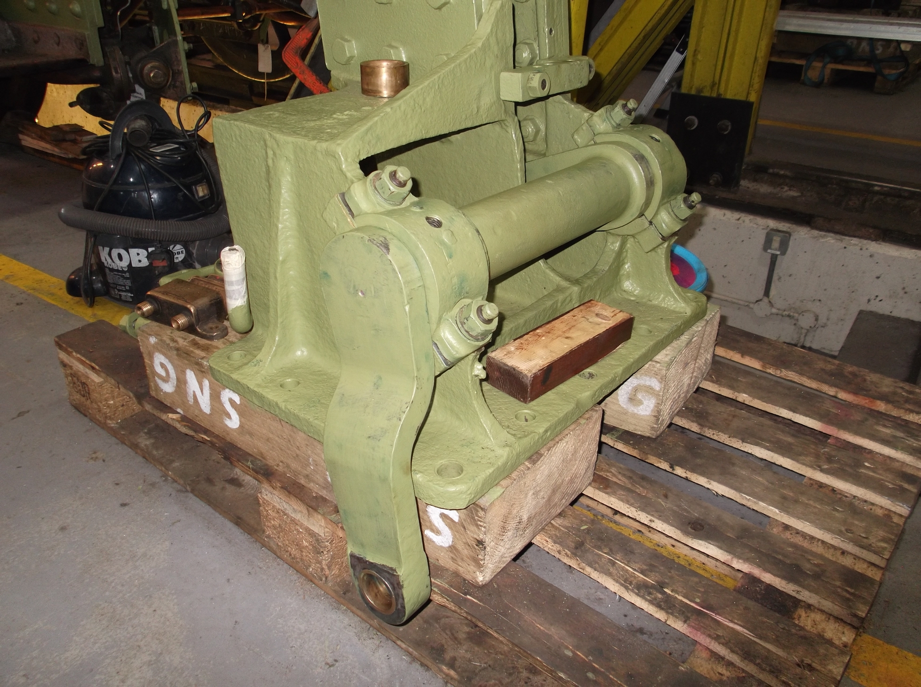
The reverser stand has been examined for wear in its bearings and it was decided that the outer shaft bearing required adjustment. As this is a split bearing this is relatively easy to do using the existing bearing, and this has now been fitted. The bearings that support the trunnions of the reverser nut housing will be replaced.
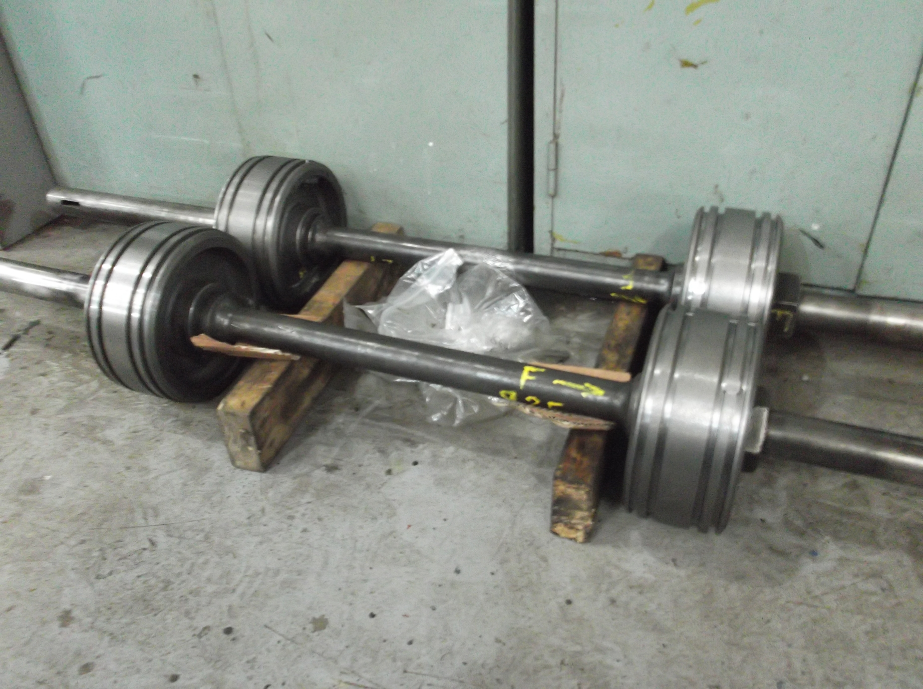
The new valve heads have been fitted to the valve spindles. They are all a good fit on the diameter of the spindles and butt up well to the spindle collars. The spindles have also been closely examined for knocks and burrs and any found have been carefully removed. The overall distance over the head ring grooves will be accurately measured and set to correspond to the distance between the valve liner ports, then the heads will be finally keyed to the spindles.
Week commencing 14 May
The air pump governor has been remounted on the driver’s side of the loco this week. It was mounted on the fireman’s side, but we decided to move it to the driver’s side, as this is the safer side of the loco. If a fault develops with the governor it can affect the operation of the air pump, which it controls. The control can be overridden to keep the air pump going and maintain the operation of the air brake system. To do this requires access to the governor. On the driver’s side that means accessing the governor possibly next to another running line. The fireman’s side is more likely to be facing the lineside.
The ashpan hopper and damper operating gear was retrieved from store this week and fitted to the loco. The installation of these parts will assist in the rerouting of the pipework to and from the governor.
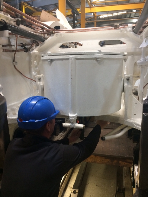
Piping of the air brake system continues at the rear of the loco. Our Chief Mechanical Engineer and the pipe fitting team have reviewed the system schematics and a number of modifications will be made to allow the repositioning of tees and gauge take offs, in order to ‘tidy’ the system and improve accessibility.
The new rings for the air pump shuttle valve were brought in this week and fitted. The air pump was tried but operation was not much improved on when the old rings were fitted. Again, operation was satisfactory when valve packing was used in one of the ring grooves. Attention then turned to the shuttle which does have a very large clearance in its bore, so that there is very little of the rings in the shuttle piston groove, perhaps leading to excessive leakage around the inside of the rings. It was decided that a new shuttle will be made and tried, reducing the shuttle piston clearance.
New hinges have now been fitted to the ashpan damper screen and some tweaking will be required to get the fit just right. Some small gaps here and there around the damper door hinges are being filled by small pieces welded in.
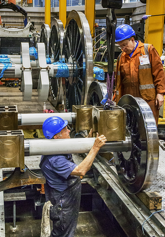
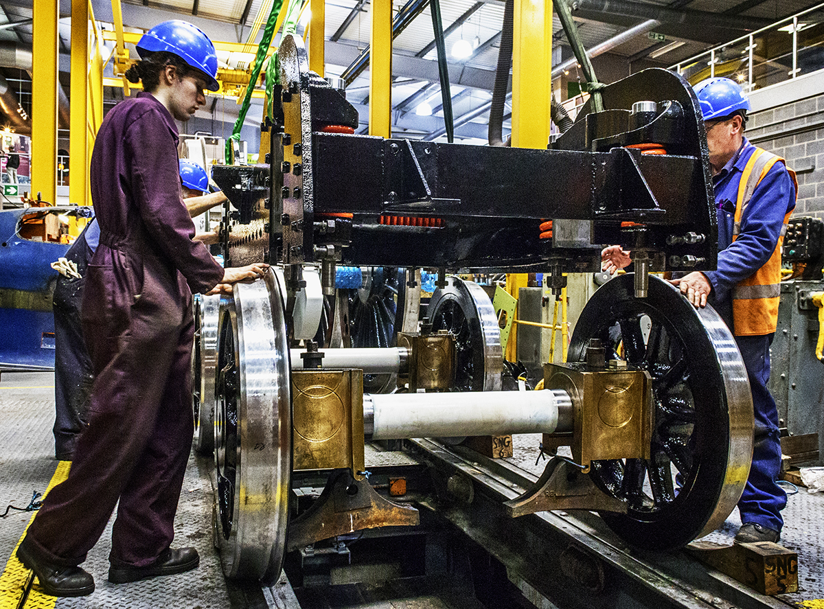
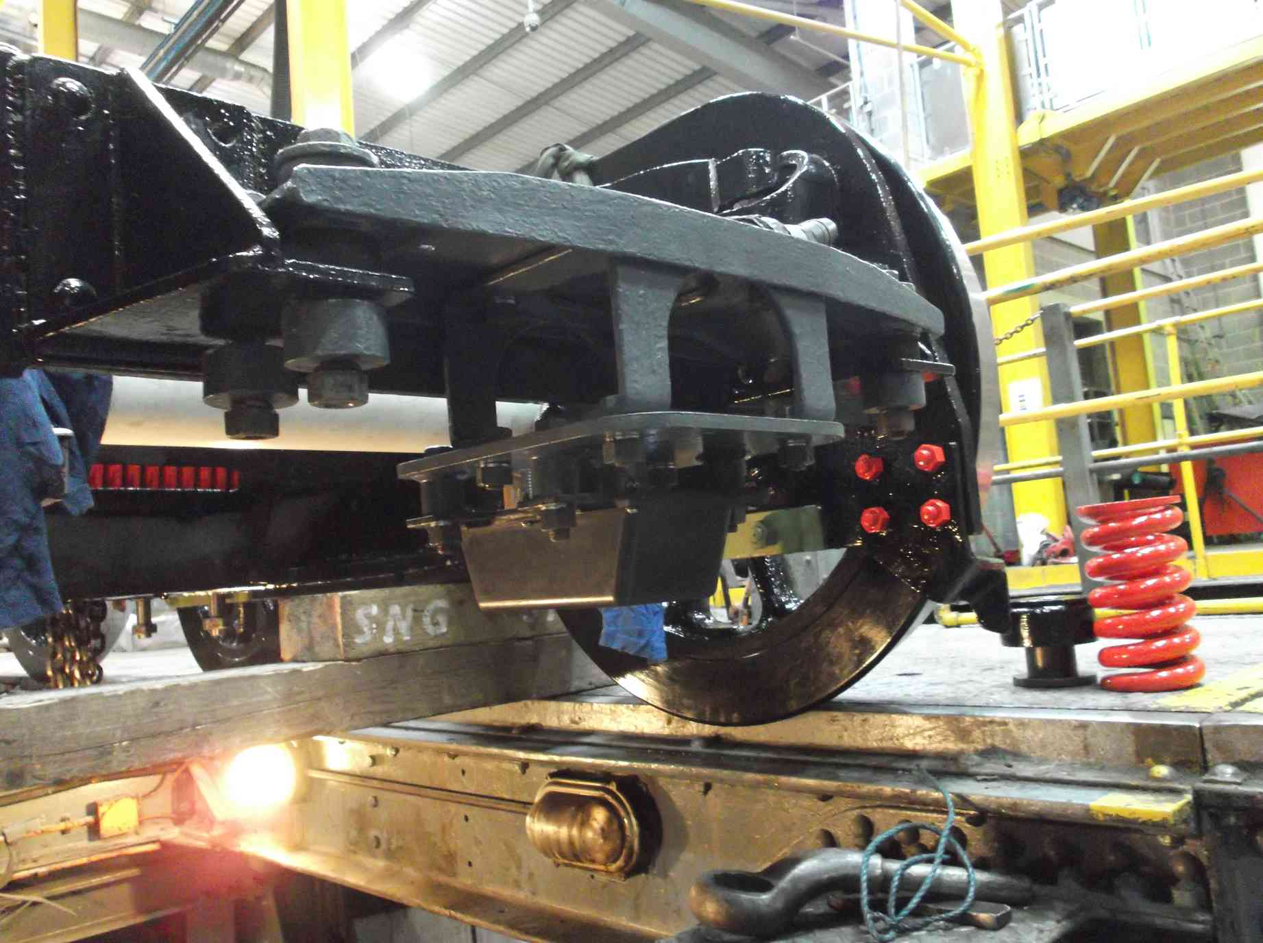
The bogie reassembly took place this week, now the painting team have finished painting the bogie springs. Just about every Engineering Team member in attendance this week played a part in it. All the bearing surfaces were scrupulously cleaned and lubricated with new oil. As we have the bogie on the wheel drop, under the overhead crane it was a relatively straight forward job, after easing the fit between the axleboxes and underkeep trays. After the wheels were in, the leading guard irons were refitted. There are still a few niggling things to sort out though.


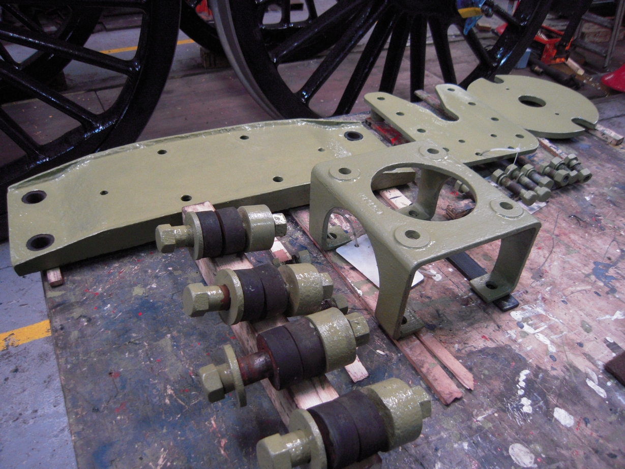
At the front of the bogie are brackets and carriers for the AWS/TPWS equipment. These were retrieved from store, cleaned and are now painted in primer. These will be refitted to the bogie before the bogie is refitted to the loco.
New studs were fitted to the superheater header this week. Unfortunately some of the studs have gone further into the header than expected so they will have to be replaced by longer studs.
New plate has now been supplied for the tender corridor roof—six sections in total, rolled to the correct dimensions, reproducing the individual sections originally fitted to the tender. All the quotes have now been received for the tender tank lift.
The new piston valve heads for the right and middle engines fitted last week were measured for positioning on the spindles this week. Everything looks to be pretty much to drawing. Rings will be ordered and final measurements over the end rings will be taken. The valves are driven from the return cranks on the driving wheels so attention has now turned to this system. The expansion links were retrieved from store and dismantled by our 007 Gang of junior volunteers. After laying out the component parts they were thoroughly cleaned as they will require testing for defects. The clearances between the die blocks and running surfaces of the expansion links were checked.
The right-hand return crank has been separated from the return crank rod and will require fitting to the crank pin. The crank pins on the driving wheelset are new, being fitted during retyring. Initially measurements of the crank and crank pin end were taken and then the crank tried on, confirming that there is a quite a bit of fitting work required here.
Weeks commencing 21 May and 28 May
The coupled wheels were given their final coat of varnish by the painting team, who went into the workshop on our usual day off to avoid any dust contamination of the finish. They look great.
The ashpan is very nearly finished, as far as the work that can be done at York goes. There are just the spark screen securing bolts waiting to be fitted. There was one before but this time two will be fitted, one either side of the screen for extra security.
The holes for the bogie sidebearers fitted to the loco have been finish reamed and we have come up with a scheme to ensure a good fit. After examination of the existing sidebearers, we decided that the work of recovering and fitting them would be excessive and decided instead to fit new assemblies. Plate has been ordered to make up the new fabrications. The faces that the sidebearers mate with have been dressed.
The horizontal hornstay holes are now being countersunk with a special tool which is guided in the hole centre by machined bushes. It takes a lot of setting up, so this job may continue for a couple of weeks yet, but the results are very good.
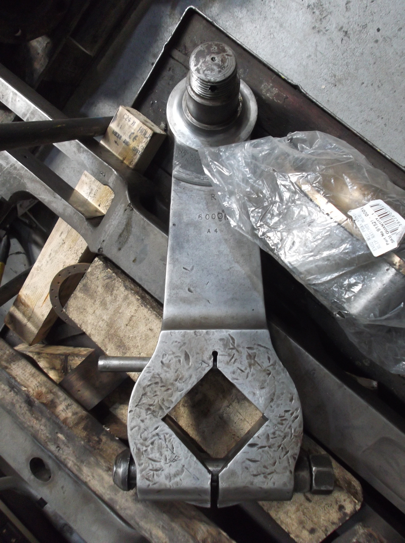
We are currently working towards the fitting of the outside valves, so the assembly that drives the valves from the driving crankpins is being examined. The expansion links have been deep cleaned and examined for cracks and wear. The die blocks that run in the expansion links have also been examined. The components are cleaned and dye-penned during the week, then our CME does the final measurements at the end of the week—a system that is working well.
The valve assembly includes the trailing outside steamchest and valve covers. These were cleaned when removed from the loco but have now been stripped of paint and are being closely examined. They are stamped with the original engine order number so presumably they are the original LNER fittings—in fact they are stamped with the LNER diamond symbol that the frames and bogie carry. As you would expect from components of this age they are a little battle-scarred, with evidence of previous repairs, so are being examined very carefully.
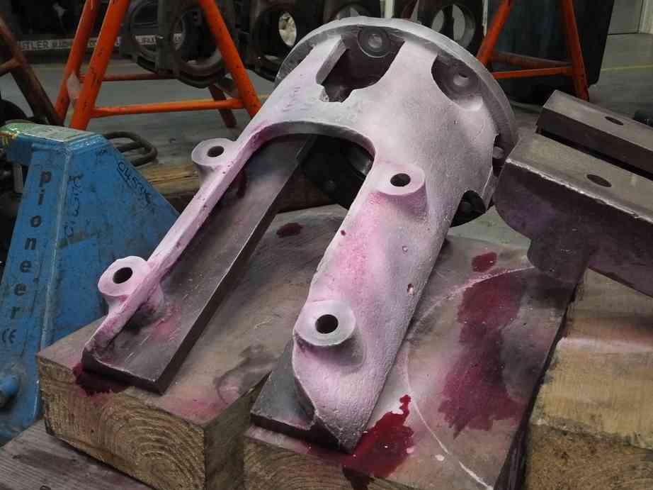
The radius rods have now been cleaned and examined and found to be defect free. The radius rod die blocks and slots have also been examined. The lifting links, bushes and expansion link bearing assemblies have also been examined and our CME is identifying the refurbishment work that is required.
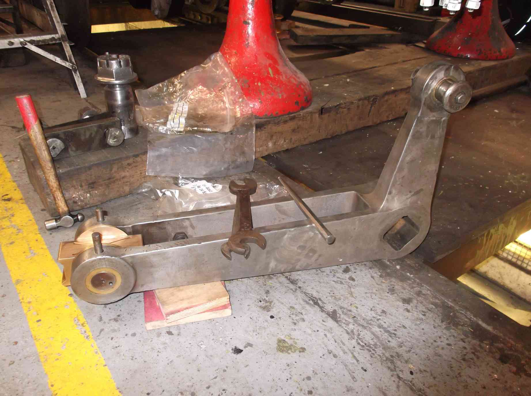
The left-hand return crank and rod were dismantled to release the return crank. The crank was then tried onto the crank pin to examine the fit. Both cranks will need careful fitting.
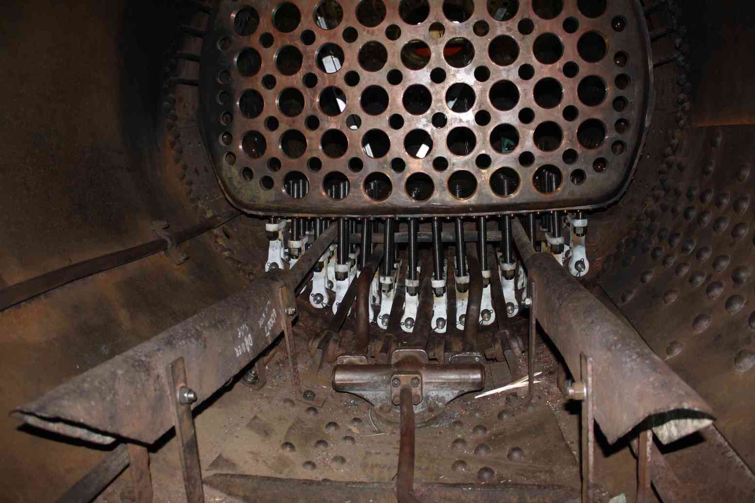
Work continues on the superheater header sealing for pressure test. We have been on this job for a few weeks now—with all the flanges requiring sealing up and all the element holes requiring bunging there’s a lot to do. We have been allowed to use the museum’s rubber bungs, which are compressed in place by through bolts made for testing 60103’s header. A plate is being manufactured for the main steam pipe as the one we had has now been sent to Llangollen for the boiler.
The sizes of the shims for the slidebars has been finalised and new plate is now on order.
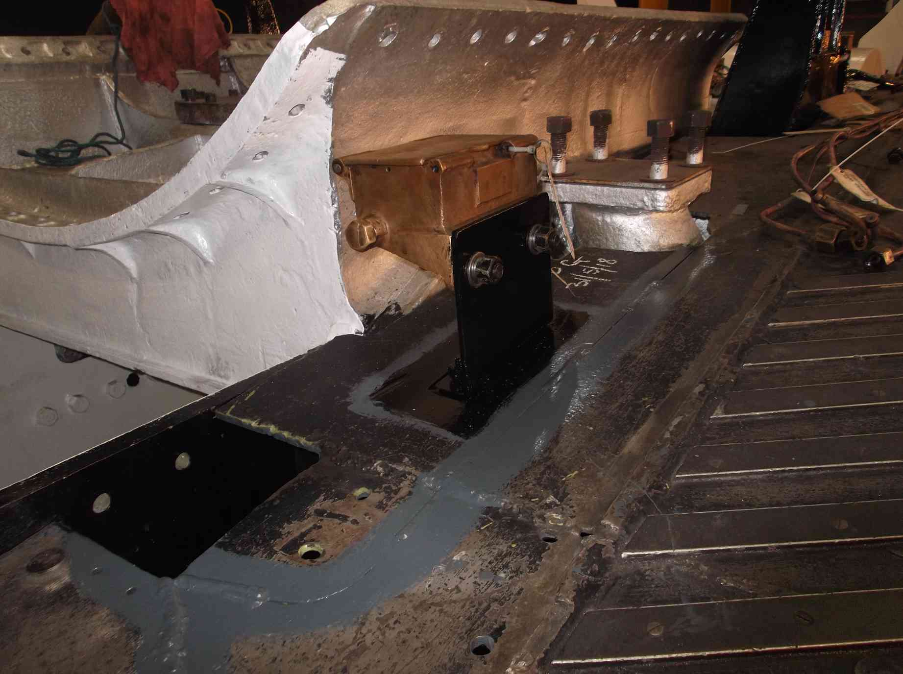
We had removed sections of footplating over the tops of the cylinders so that we could access the outside cylinder mounting bolts for the work that they required. Now that they are all fitted, the nuts on the bolts were given a final torque check and the plating replaced. The plates were cleaned and prepped and stitch welded in place. Securing like this means they can be easily cut out again in future. The mounting brackets for the leading oil boxes are on this section of footplating, so these have been given a final clean and new bolts have been fitted. The oil boxes have now been fitted in place.
At Llangollen the foundation ring repairs are now completed and it has been reunited with the boiler. The new copper for the remaining combustion chamber stays is to be chemically analysed to ensure it has the correct composition before manufacturing the stays. We have supplied Llangollen with a drawing of the clamp arrangement between the internal steam pipe and regulator so that new parts can be manufactured.

The re-installation and modification of the pipework continues. As reported, the pipe fitting team and our CME have reviewed the system and new piping is now being made. Part of this reorganisation is the moving of the air pump governor, but there is also the reorganisation under the driver’s position, where there are various take-offs for gauges and driver’s controls.
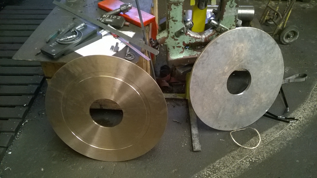
A key part of the cab assembly is the reverser stand, which locates the driver’s air brake controls. This in turn fixes the positions of the pipes in that area of the cab, so we are working on the completion of the reverser overhaul so it can be fitted. The large reverser nut, a substantial bronze component, has been weld repaired by engineering team volunteers and will now be machined back to dimensions. The pawl and indent that release the nut and operate the vacuum clutch valve are being refurbished, along with the linkage. The damper door linkage is also being worked on.
The vacuum brake ejector cam has been repaired and this was refitted to the ejector. The driver’s handle lever was removed to allow the refitting of the cam and is being repainted before refitting. The air brake pump new control piston has been made complete with new rings. It is yet to be fitted and tested.
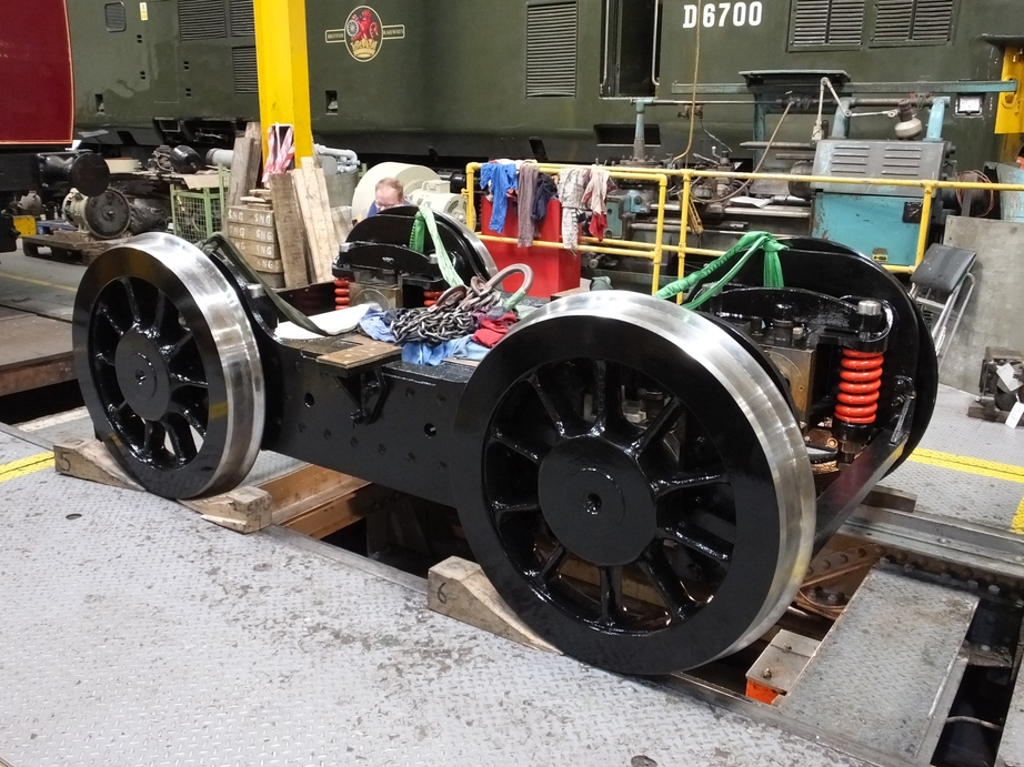
The reassembly of the bogie continues, though from recent photographs with it back on its wheels it may look complete. Now he AWS and TPWS are being refitted. The AWS in particular is carried on substantial bracketry, which has been painted to undercoat and refitted. When tightening the bolts, we noticed some of the rubber anti-vibration bushes have cracking so we decided decided to replace them. The front of the bogie has been put on packing as the spring hanger bolts are to be drilled for split pins, which has to be done off the bogie.
More work has been done on the tender corridor. The original 1928 tender top beading, hidden by the later streamlining, has been removed to find a sound edge for welding to new plate. It was secured by rivets, all of which had to be individually removed. A section of new plate has been tried in and further fitting will be required. Further planning for the tender tank lift has been done and the lifting firm we are discussing the work with have been very generous with their time.
This is the 28th update. You can read all the previous instalments here.
Dear Sir N G team, what an awesome project, I am staggered. The detailed descriptions of the work and materials needed for such a complicated locomotive is staggering.
Very best wishes and thanks for looking after the real thing, not the 4mm model I was lucky enough to have.