Our library and archive centre is a busy part of the museum. Our visitor numbers show that we’re helping more researchers find the answer to their questions every year. But sometimes we’re contacted by researchers who can’t make the journey to the museum –and that’s why we’ve introduced the Inreach service. In return for a donation of £20 you can hire an expert volunteer researcher for a day to search through our collections and find answers to your questions.
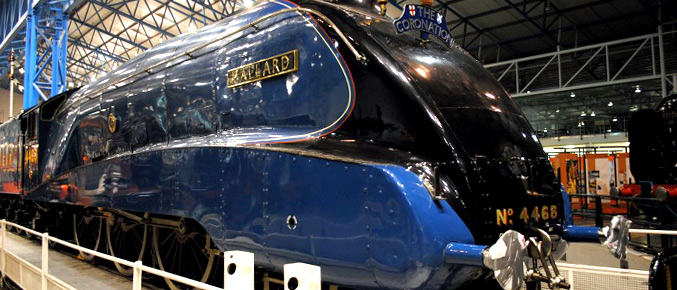
Recently the Inreach team got excited when we were presented with an interesting challenge. One of our enquirers wanted to verify a fact he had heard about the A4 Pacific class of locomotive – like Mallard, built by the London & North Eastern Railway (LNER). The story goes that the locomotives were so fast that the LNER’s civil engineers became scared that the trains might start ripping up the track and cause an accident. They demanded that speed recorders were fitted (similar to a speedometer in your car) to a whole class of locomotive for the first time in Britain.

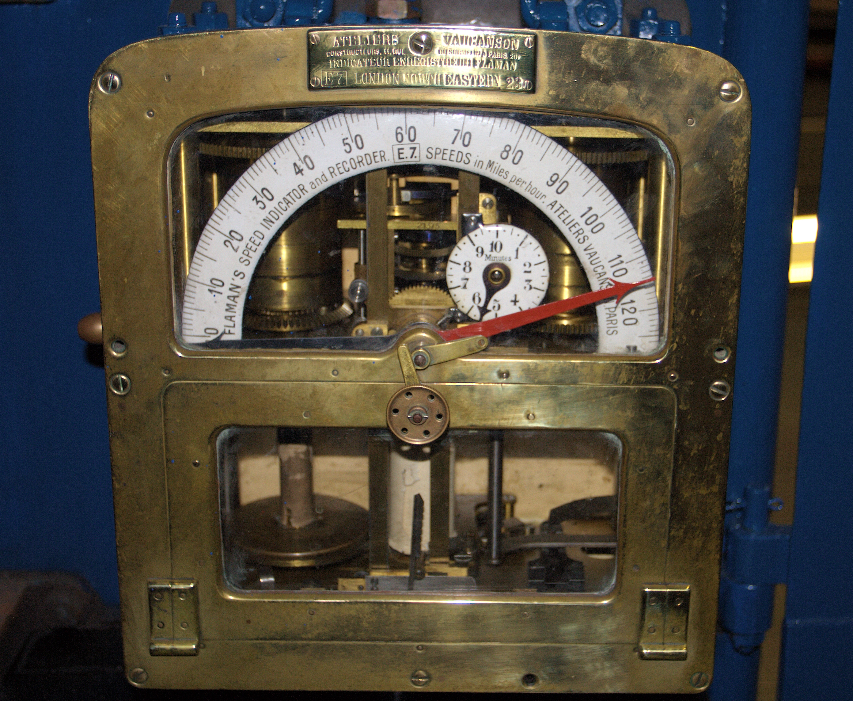
It might be a surprise to anyone that hasn’t seen a steam locomotive footplate before that very few British locos were ever fitted with anything like a speedometer. Judging the speed of the train was done purely through the driver’s skill, using his route knowledge and mileposts next to the track. This is despite the fact that speed recording equipment had existed for decades. Indeed, in France, 80% of locos had been fitted with a Flaman speed recorder by 1914 – 21 years before the first A4 was built.

Unfortunately the story about the engineers’ fear of the A4s wasn’t going to stack up. Although it’s clear that all of the A4s were fitted with the speed recorders from new, it wasn’t the first time that a whole class of locomotive had been fitted with them on the LNER. In 1934, Sir Nigel Gresley designed the P2 class for express trains between Edinburgh and Aberdeen. The first of the class, Cock o’ the North, was sent to France after it was built to be tested at Vitry near Paris. To run on the French railways it needed a speed recorder, so it was fitted with one called a Telos from a London firm called the Hasler Telegraph Company. It was decided to fit the other five locomotives in the class with one – probably to prevent drivers speeding on the tight curves of the line to Aberdeen. Since the last P2 was built five months before the first A4, Silver Link, was completed, we had proven the A4 theory wrong.
We did however find out one interesting thing about the A4s in our research. The Silver Jubilee was a streamlined train, first hauled by the A4 Silver Link between London King’s Cross and Newcastle. The LNER’s staff magazine reported after the first running of the train that:
“a novel fixture is the electric speedometer which has been installed in the first-class restaurant car for the convenience of passengers interested in the running of the train”.
This wasn’t the end of the story though. The book Our Home Railways, How They Began and How They Are Worked by W J Gordon in 1910 (follow the link to the free E-Book) when referring to the London, Brighton & South Coast Railway (LB&SCR) mentions that “every Brighton engine has, in the cab, a speed indicator”. That was 25 years before the LNER finished the P2s. This clearly needed further investigation.
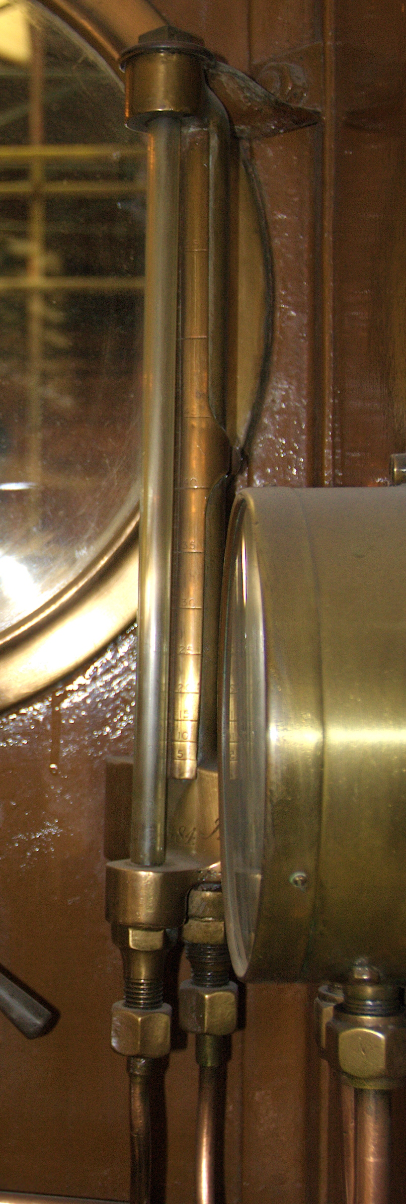
In his presidential address to the Institution of Locomotive Engineers in 1948, Lt-Col Harold Rudgard credits William Stroudley with the invention of a speed indicator1. Stroudley’s speed indicator was a novel design. A fan was driven from the axle of the rear trailing wheel by a belt. This pumped air into a gauge glass on the footplate. Higher speeds would force a ball sat in the glass upwards and this could be read against a gauge next to the glass.
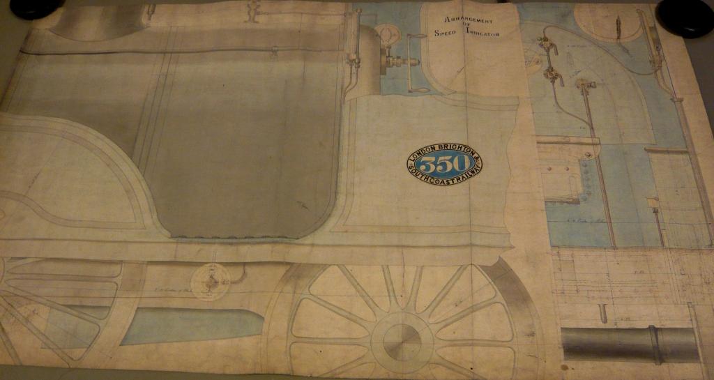
Our attention soon turned to the London, Brighton and South Coast Railway Class G – designed by William Stroudley. The first of Stroudley’s speed indicators was fitted to locomotive Grosvenor, built in 1874. 13 more locomotives were ordered with some modifications, the last being delivered in 1881. Of course the fitting of the speed indicator to the prototype could have been a one-off. so the clincher came in the form of two images we found. The first was a photograph of No.336 Edinburgh, clearly showing the speed indicator fitted to the frames behind the single driving wheel. The second was a set of drawings in our archive showing Stroudley’s patented speed indicator. One drawing shows the speed indicator as fitted to No.350 Southbourne (below).

From this we can be fairly certain that speed indicators were fitted to the whole class from new, and we believe this was the first time this happened in Britain. This was in fact 60 years before the LNER fitted its P2s with speed recorders, and even 27 years before the French patented their Flaman speed recorder. The LB&SCR continued to fit speed indicators to its locomotives. Indeed, one survives in the National Collection as fitted to Gladstone, and you can see it in Station Hall:

Of course, it’s nearly impossible to say how many accidents or lives could have been saved if the speed indicator had been fitted to other locomotives in Britain in addition to those on the Brighton lines. We can’t see an obvious reason why Stroudley and the LB&SCR introduced them when we can find no other pre-grouping company2 that decided to use them.
By the way, if you know something about speed indicators that we’ve missed or of other uses of speed indicators before the LB&SCR Class G, let us know by commenting below. For more about the Inreach service or if you have your own enquiry, see our enquiries page for advice and contact details.
1 A quick note: Stroudley didn’t invent the first speed indicator. We have one in our collection that was made in 1858, but we have no idea where it came from and we believe it was a one-off.
2 Except for the London & South Western Railway, which from our drawings collection appears to have tried a few speed recorders around 1909, but still much later than the LB&SCR.
I think the description of the LBSCR speedometer is a bit wrong here. According to HJ Campbell-Cornwall, in “Stroudley, Craftsman of Steam”, the “fan” (actually a paddlewheel or impeller) rotated in water, not air. This pushed a column of water up a tube, presumably with the ball floating on top to make the level easy to see. HJCC goes to some length to describe the mechanism for stopping leaks, so I am sure he is right. DL Bradley further notes that the water had glycerine added to keep it from freezing in the winter.
C Hamilton-Ellis in his LBSCR book has the action the other way (i.e. an air fan pushing on a column of water, as alluded to above), but I think the agreement between Bradley and HJCC is probably conclusive that, on this occassion, CHE got it wrong.
HJCC also alludes to an earlier speed indicator designed by Ramsbottom, but which was never adopted.
Incidentally, apart from the G class, Terrier No. 40 “Brighton” also had a speed indicator, the only Terrier thus fitted. This was of course the Paris Exhibition engine of 1878 (another French Connection!), though I suspect the fitting was to help showcase the latest British technological advances, rather than due to any legislative need on the French Railways at that time. This loco is now preserved on the Isle of Wight as W11 “Newport”.
Tom
The pump appears to be below the running board and the indicator is presumably up in the cab. If the (water) pump creates a pressure head at max speed equal to a column of water about the length of the gauge glass, what creates the pressure to get the water up to the zero point?
This would not be a problem if the pressure signal was transmitted to the cab by air pressure (the weight of six feet of air is negligible here). The necessary air pressure would be most conveniently created by an air pump!
Having thought again about the air/water debate, the water reservoir must be at the height of the cab. If the system uses a water pump, the problem of the head between the pump and the cab is then solved , with the zero speed height of the water in the gauge being the reservoir water level. In a water pumped system, the water would feed from a reservoir open to atmosphere down to the pump and back up to the gauge.. In the air pumped system, the down pipe would not be needed.. The air pipe from the pump would feed up to a closed reservoir, with the air pressure on the surface of the water forcing the water up the gauge. I haven`t seen the drawings, but if there is enough detail to show the circuitry, it should be possible sort the air/water issue
Thank you for your comments. We were aware of some confusion about the operation of the speed indicator and were leaning towards a water pump until we found the reference by Hamilton-Ellis. The drawings of the cab fittings for the speed indicator are far from conclusive but there are more drawings in the collection that we haven’t examined yet.
“One drawing shows the speed indicator as fitted to No.350 Southbourne”
except that it’s on the left-hand side in the drawing but on the right in photographs.
“…we can be fairly certain that speed indicators were fitted to the whole class from new, and we believe this was the first time this happened in Britain.”
Photographic evidence suggests it is not that straightforward.
I have photographs of 325,326,336,338,343 and 350 with speed indicators, but 326,327,329 to 332,334,335,337 to 339,341,342,344 and 349 without. Of the remainder I can find no sufficiently clear right-hand views. Note that 326 and 338 appear in both lists.
It is possible that they all had one initially and it was later removed, but evidence is lacking.
Hi Christopher,I have indeed thought about it. While it is true that grouping occluded quads could reduce the face count, in practice it does have some drawbacks, the most noticeable of which is that it could drastically increase the amount of overdraw. I’m not really sure if it would be a net benefit or cost, but my gut tells me that it would probably be the latter. If you ever try it, let me know what your results are! (I’d be happy to have my intuition proven wrong.)
http://mariusbeckdahle.tumblr.com/post/141480959246/super-soup-tomato-vegetable-version
The Stroudley-type speedindicator was used by the Danish State Railways. It is descriped in the textbook for enginemen, version 1901, 1909 and 1925 with a section drawing.
At the West-Zealand preserved railway, we expect to have the steam-engine OHJ 38 running again 2017 with the Stroudley speedindicator in working order.
I can supply a copy of the drawning an make a translation off the text if needed.
Thanks for that Lars. That’s an interesting piece of the story as I hadn’t seen any evidence yet that these were used anywhere other than the LBSCR. Could you get in touch with me via search.engine@nrm.org.uk
In addition to Lars’ comment, it might be interesting to add that these speed indicators have also been in use on several Dutch railways. I’ve seen references to their use on several express locomotives, on the major companies of the 1900 era (H.S.M; S.S.; N.C.S. and N.B.D.S.). Both Gatsonides and Harterink & Mook – standard books on locomotive operation – describe the functioning. If interested, I may be able to provide scans and a translation.
Both books, by the way, describe the speed indicators operating with water. The reservoir is attached to the bottom of the tube, with two pipes going down to the impellor driven from the axle. To account for water loss, the scale may be slid up and down, or water can be added to the reservoir via a plug.
Interesting facts about LBSCR and speedometers.
I would like to why they changed the pony truck axle driven speedometer to a Smiths speedometer on the left trailing driving axle by a crank pin on 70000-70054 by the 1960’s
T.R. Harding & Son of Leeds manufactured a locomotive speedometer (as they called it – possibly the first use of this term) or speed indicator that was exhibited at a meeting of the Leeds Philosophical Society on 1 February 1872. It was exhibited at the Vienna Exhibition in 1873 and there is a record of its use on a locomotive in The Engineer in 1877, though the impression given by the article is that it was in fairly widespread use by this date. We have no evidence that it was fitted to a locomotive prior to the Stroudley installation to the Grosvenor in 1874, but it seems entirely possible.
There were some relatively simple methods available for calculating speed early on but I do not know if they were ever used! First, rail track was mass-produced at a steelworks and the standard length of each one was 60ft. So, every time we heard “De-dum-de-dum” as we travelled along meant we had moved another 60ft! Applying a bit of mathematics to this tells us if we count the number of “De-dum-de-dums” that we hear (and feel!) in 41 seconds then it gives us the speed in mph! (Try it out on a preserved line such as NYMR and you will find that it works!)
The next method was a bit more complicated but not impossible! It requires knowledge of the number of cylinders plus wheel diameter of the loco in question. For example, Mallard and Flying Scotsman both had three cylinders and drive wheel diameters of 80 inches. Every cylinder has to discharge twice per revolution as they moved backwards and forwards, so our locos of interest have six puffs and approx 21ft travel per revolution. So, applying a bit more mathematics to this tells us if we count the number of “Puff-puff-puf-puff-puff-puffs” that we hear (and count) in 14 seconds then it should also gives us the speed in mph! (Counting individual puffs is suggested to be a bit too tricky to do but you can try!)
Has this been tried before?